EP0932028A1 - Capteur optique de rotation - Google Patents
Capteur optique de rotation Download PDFInfo
- Publication number
- EP0932028A1 EP0932028A1 EP98101028A EP98101028A EP0932028A1 EP 0932028 A1 EP0932028 A1 EP 0932028A1 EP 98101028 A EP98101028 A EP 98101028A EP 98101028 A EP98101028 A EP 98101028A EP 0932028 A1 EP0932028 A1 EP 0932028A1
- Authority
- EP
- European Patent Office
- Prior art keywords
- circuit board
- sensing device
- optical rotation
- rotation sensing
- panel
- Prior art date
- Legal status (The legal status is an assumption and is not a legal conclusion. Google has not performed a legal analysis and makes no representation as to the accuracy of the status listed.)
- Withdrawn
Links
- 230000003287 optical effect Effects 0.000 title claims abstract description 25
- 238000010276 construction Methods 0.000 abstract 1
- 238000006073 displacement reaction Methods 0.000 description 4
Images


Classifications
-
- G—PHYSICS
- G01—MEASURING; TESTING
- G01D—MEASURING NOT SPECIALLY ADAPTED FOR A SPECIFIC VARIABLE; ARRANGEMENTS FOR MEASURING TWO OR MORE VARIABLES NOT COVERED IN A SINGLE OTHER SUBCLASS; TARIFF METERING APPARATUS; MEASURING OR TESTING NOT OTHERWISE PROVIDED FOR
- G01D5/00—Mechanical means for transferring the output of a sensing member; Means for converting the output of a sensing member to another variable where the form or nature of the sensing member does not constrain the means for converting; Transducers not specially adapted for a specific variable
- G01D5/26—Mechanical means for transferring the output of a sensing member; Means for converting the output of a sensing member to another variable where the form or nature of the sensing member does not constrain the means for converting; Transducers not specially adapted for a specific variable characterised by optical transfer means, i.e. using infrared, visible, or ultraviolet light
- G01D5/32—Mechanical means for transferring the output of a sensing member; Means for converting the output of a sensing member to another variable where the form or nature of the sensing member does not constrain the means for converting; Transducers not specially adapted for a specific variable characterised by optical transfer means, i.e. using infrared, visible, or ultraviolet light with attenuation or whole or partial obturation of beams of light
- G01D5/34—Mechanical means for transferring the output of a sensing member; Means for converting the output of a sensing member to another variable where the form or nature of the sensing member does not constrain the means for converting; Transducers not specially adapted for a specific variable characterised by optical transfer means, i.e. using infrared, visible, or ultraviolet light with attenuation or whole or partial obturation of beams of light the beams of light being detected by photocells
- G01D5/347—Mechanical means for transferring the output of a sensing member; Means for converting the output of a sensing member to another variable where the form or nature of the sensing member does not constrain the means for converting; Transducers not specially adapted for a specific variable characterised by optical transfer means, i.e. using infrared, visible, or ultraviolet light with attenuation or whole or partial obturation of beams of light the beams of light being detected by photocells using displacement encoding scales
- G01D5/3473—Circular or rotary encoders
-
- G—PHYSICS
- G01—MEASURING; TESTING
- G01D—MEASURING NOT SPECIALLY ADAPTED FOR A SPECIFIC VARIABLE; ARRANGEMENTS FOR MEASURING TWO OR MORE VARIABLES NOT COVERED IN A SINGLE OTHER SUBCLASS; TARIFF METERING APPARATUS; MEASURING OR TESTING NOT OTHERWISE PROVIDED FOR
- G01D11/00—Component parts of measuring arrangements not specially adapted for a specific variable
- G01D11/24—Housings ; Casings for instruments
Definitions
- the present invention relates to an optical rotation sensing device comprising the features of the preamble of claim 1.
- the axle of the rotational module is mounted in parallel to the circuit board, the panel including the position holes being disc-shaped and extending in a plane perpendicular to the circuit board. Accordingly, the sensing device requires relatively much space which, however, may be rare in an electronic device including any such sensing device as, e.g., a computer mouse.
- the present invention as claimed aims at providing an optical sensing device of the kind as specified in the preamble of claim 1, in which the space required is substantially reduced.
- the axle of the rotational module extends perpendicular to the circuit board the space required is considerably reduced in respect to corresponding prior art sensing devices.
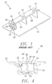
- a prior art optical rotation sensing device 10 comprises a circuit board 12, a rotational module 14, two mounting arms 16, an LED (light emitting diode) 18, and a sensor 20.
- the module 14 comprises a disc-shaped circular pannel 22 having a plurality of position holes 24 arranged along its periphery and an axle 26 perpendicularly installed at the center of the panel 22.
- the two mounting arms 16 are themselves vertically mounted on the circuit board 12 and each comprises a mounting hole 17 near its top end.
- the axle 26 is rotatably mounted in the two mounting holes 17, in parallel to the circuit board 12, so that the position holes 24 of the circular panel 22 can pass between the LED 18 and the sensor 20 on the circuit board 12.
- the axle 26 is rotated, for example by a roller ball within a mouse, the position holes 24 of the panel 22 will pass by the LED 18 and the sensor 20 so that displacement signals are generated by the sensor 20 to measure the rotations of the module 14.
- An optical sensing device 30 comprises a circuit board 32, a rotational module 34 and a cap-shaped mounting member 36 for mounting the module 34 to the circuit board 32.
- the circuit board 32 is horizontally positioned in use, as in a mouse, and comprises a top side 44, a bottom side 46, and a through hole 38.
- the module 34 comprises a cap-shaped circular panel 50 having a plurality of position holes 54 along a cylindrical collar thereof and an axle 48 at its center for rotating the panel 50.
- the bottom side 46 of the circuit board 32 is equipped with an LED 40 and a sensor 42 for detecting light emitted from the LED 40 that has passed through any of the position holes 54.
- the mounting member 36 comprises a circular chamber 58 open to the top for receiving the panel 50 of the module 34, an interior end, 51, of the axle 48 extending into a corresponding central recess 53 in the bottom of the mounting member 36.
- the panel 50 is rotatably mounted on the bottom side 46 of the circuit board 32 with the axle 48 extending perpendicularly to the top side 44 of the circuit board 32 through the through hole 38 so that the panel 50 can be rotated from the top side 44 of the circuit board 32.
- its position holes 54 will pass by the LED 40 and sensor 42 to generate displacement signals so that rotations of the module 34 can be calculated from the displacement signals.
- FIG. 7 Another optical sensing device 70 according to the invention, as shown in the Figs. 5 - 7, comprises a circuit board 72, a rotational module 74, and a cap-shaped mounting member 76 for mounting the module 74 to the circuit board 72.
- the circuit board 72 in use, again is horizontally positioned. It comprises a top side 84 and a bottom side 86.
- the module 74 comprises a disc-shaped circular panel 90 having a plurality of position holes 92 along its periphery, and an axle 88 perpendicularly installed at the center of the panel 90 for rotating it.
- the top side 84 of the circuit board 72 is equipped with an LED 80 at some distance above the circuit board 72 and a sensor 82 for detecting light emitted from the LED 80 which has passed through any of the position holes 92, the sensor being mounted flat on the circuit board 72.
- the mounting member 76 is used for rotatably mounting the module 74 on the circuit board 72 with the axle 88 perpendicular to the circuit board 72 and the circular panel 90 rotatably positioned between the LED 80 and sensor 82.
- the mounting member 76 comprises a circular chamber 96 open to the bottom and a through hole 78 in its top.
- the panel 90 is rotatably installed inside the chamber 96 and the mounting means 76 is installed on the top side 84 of the circuit board 72, one end, 98, of the axle 88 extending into a recess 100 in the circuit board 72 and another end, 102, extending through the through hole 78 of the mounting member 76, so that the module 74 can be rotated from the top side 84 of the circuit board 72.
- the position holes 92 of the panel 90 will pass between the LED 80 and sensor 82 to generate displacement signals so that rotations of the module 74 can be calculated therefrom.
- either of the two different rotational modules 34 and 74 previously described can be employed with its circular pannel 50 and 90, respectively, above or below the associated circuit board. Since in each case the axle of the rotational module extends perpendicularly with respect to the circuit board the sensing devices of the present invention can be made very compact and much smaller than a corresponding prior art sensing device as shown, e.g., in Fig. 1.
Landscapes
- Physics & Mathematics (AREA)
- General Physics & Mathematics (AREA)
- Optical Transform (AREA)
Priority Applications (1)
| Application Number | Priority Date | Filing Date | Title |
|---|---|---|---|
| EP98101028A EP0932028A1 (fr) | 1998-01-22 | 1998-01-22 | Capteur optique de rotation |
Applications Claiming Priority (1)
| Application Number | Priority Date | Filing Date | Title |
|---|---|---|---|
| EP98101028A EP0932028A1 (fr) | 1998-01-22 | 1998-01-22 | Capteur optique de rotation |
Publications (1)
| Publication Number | Publication Date |
|---|---|
| EP0932028A1 true EP0932028A1 (fr) | 1999-07-28 |
Family
ID=8231292
Family Applications (1)
| Application Number | Title | Priority Date | Filing Date |
|---|---|---|---|
| EP98101028A Withdrawn EP0932028A1 (fr) | 1998-01-22 | 1998-01-22 | Capteur optique de rotation |
Country Status (1)
| Country | Link |
|---|---|
| EP (1) | EP0932028A1 (fr) |
Cited By (2)
| Publication number | Priority date | Publication date | Assignee | Title |
|---|---|---|---|---|
| US20120187222A1 (en) * | 2011-01-25 | 2012-07-26 | Galili Giora | Cooling and washing system |
| CN109945914A (zh) * | 2017-12-20 | 2019-06-28 | 长沙行深智能科技有限公司 | 一种多层传感器 |
Citations (4)
| Publication number | Priority date | Publication date | Assignee | Title |
|---|---|---|---|---|
| US4593269A (en) * | 1983-11-15 | 1986-06-03 | Matsushita Electric Works, Ltd. | Compact optional rotary encoder having adjustable light admitting and receiving components |
| US4712005A (en) * | 1985-12-19 | 1987-12-08 | Kollmorgen Technologies Corporation | Floating mask encoder with assembly spacer |
| GB2223575A (en) * | 1988-09-02 | 1990-04-11 | Alcatel Business Systems | Optical position encoder |
| JPH09280896A (ja) * | 1996-04-15 | 1997-10-31 | Japan Aviation Electron Ind Ltd | 光学式エンコーダ |
-
1998
- 1998-01-22 EP EP98101028A patent/EP0932028A1/fr not_active Withdrawn
Patent Citations (4)
| Publication number | Priority date | Publication date | Assignee | Title |
|---|---|---|---|---|
| US4593269A (en) * | 1983-11-15 | 1986-06-03 | Matsushita Electric Works, Ltd. | Compact optional rotary encoder having adjustable light admitting and receiving components |
| US4712005A (en) * | 1985-12-19 | 1987-12-08 | Kollmorgen Technologies Corporation | Floating mask encoder with assembly spacer |
| GB2223575A (en) * | 1988-09-02 | 1990-04-11 | Alcatel Business Systems | Optical position encoder |
| JPH09280896A (ja) * | 1996-04-15 | 1997-10-31 | Japan Aviation Electron Ind Ltd | 光学式エンコーダ |
Non-Patent Citations (1)
| Title |
|---|
| PATENT ABSTRACTS OF JAPAN vol. 098, no. 002 30 January 1998 (1998-01-30) * |
Cited By (3)
| Publication number | Priority date | Publication date | Assignee | Title |
|---|---|---|---|---|
| US20120187222A1 (en) * | 2011-01-25 | 2012-07-26 | Galili Giora | Cooling and washing system |
| CN109945914A (zh) * | 2017-12-20 | 2019-06-28 | 长沙行深智能科技有限公司 | 一种多层传感器 |
| CN109945914B (zh) * | 2017-12-20 | 2024-03-12 | 长沙行深智能科技有限公司 | 一种多层传感器 |
Similar Documents
| Publication | Publication Date | Title |
|---|---|---|
| US5047761A (en) | Pointer illuminated instrument | |
| EP1158277A1 (fr) | Instrument d'affichage éclairé | |
| KR20010092788A (ko) | 자동차의 디스플레이 계기 | |
| US6315432B1 (en) | Light-emitting diode (LED) device | |
| JPH08510343A (ja) | ジョイスティック用の光電式変位量検出装置 | |
| ES2278573T3 (es) | Aparato de control con elementos de control que pueden iluminarse. | |
| EP1020710A1 (fr) | Instrument à aiguille éclairée | |
| EP1646062B1 (fr) | Dispositif d'illumination | |
| EP0932028A1 (fr) | Capteur optique de rotation | |
| US7098895B2 (en) | Optical trackball device and electronic apparatus | |
| CN110873579A (zh) | 编码器 | |
| US20010025596A1 (en) | Heat insulation arrangement of indicating instrument | |
| JP5135222B2 (ja) | 第1および/または第2の光導波領域を有する回転インジケータを備えている自動車用の表示装置 | |
| US4171855A (en) | Multi-position electronic component mounting | |
| US7352950B2 (en) | Lightpipe with multiple projections | |
| CN1819761B (zh) | 照明装置 | |
| US20020144413A1 (en) | Multi-bit optical sensor code wheel | |
| JPH05257429A (ja) | 電子機器の表示灯取付け構造 | |
| US20050063168A1 (en) | Surface light source | |
| TWI891242B (zh) | 感測裝置 | |
| JP2002328733A (ja) | 操作入力装置 | |
| JPH0527240A (ja) | 面照明装置 | |
| US7401933B2 (en) | Mounting apparatus for light emitting diode | |
| JP3094261B2 (ja) | 光センサの取付け装置 | |
| KR20110059117A (ko) | 중공 타입 노브의 조명 구조체 |
Legal Events
| Date | Code | Title | Description |
|---|---|---|---|
| PUAI | Public reference made under article 153(3) epc to a published international application that has entered the european phase |
Free format text: ORIGINAL CODE: 0009012 |
|
| AK | Designated contracting states |
Kind code of ref document: A1 Designated state(s): AT BE CH DE DK ES FI FR GB GR IE IT LI LU MC NL PT SE |
|
| AX | Request for extension of the european patent |
Free format text: AL;LT;LV;MK;RO;SI |
|
| STAA | Information on the status of an ep patent application or granted ep patent |
Free format text: STATUS: THE APPLICATION HAS BEEN WITHDRAWN |
|
| 18W | Application withdrawn |
Withdrawal date: 19991117 |