EP0228903A2 - Magnetköpfe - Google Patents
Magnetköpfe Download PDFInfo
- Publication number
- EP0228903A2 EP0228903A2 EP86310119A EP86310119A EP0228903A2 EP 0228903 A2 EP0228903 A2 EP 0228903A2 EP 86310119 A EP86310119 A EP 86310119A EP 86310119 A EP86310119 A EP 86310119A EP 0228903 A2 EP0228903 A2 EP 0228903A2
- Authority
- EP
- European Patent Office
- Prior art keywords
- magnetic
- tape
- head
- magnetic gap
- gap
- Prior art date
- Legal status (The legal status is an assumption and is not a legal conclusion. Google has not performed a legal analysis and makes no representation as to the accuracy of the status listed.)
- Withdrawn
Links
Images
Classifications
-
- G—PHYSICS
- G11—INFORMATION STORAGE
- G11B—INFORMATION STORAGE BASED ON RELATIVE MOVEMENT BETWEEN RECORD CARRIER AND TRANSDUCER
- G11B5/00—Recording by magnetisation or demagnetisation of a record carrier; Reproducing by magnetic means; Record carriers therefor
- G11B5/127—Structure or manufacture of heads, e.g. inductive
- G11B5/29—Structure or manufacture of unitary devices formed of plural heads for more than one track
-
- G—PHYSICS
- G11—INFORMATION STORAGE
- G11B—INFORMATION STORAGE BASED ON RELATIVE MOVEMENT BETWEEN RECORD CARRIER AND TRANSDUCER
- G11B5/00—Recording by magnetisation or demagnetisation of a record carrier; Reproducing by magnetic means; Record carriers therefor
- G11B5/127—Structure or manufacture of heads, e.g. inductive
- G11B5/265—Structure or manufacture of a head with more than one gap for erasing, recording or reproducing on the same track
- G11B5/2652—Structure or manufacture of a head with more than one gap for erasing, recording or reproducing on the same track with more than one gap simultaneously operative
- G11B5/2654—Structure or manufacture of a head with more than one gap for erasing, recording or reproducing on the same track with more than one gap simultaneously operative for recording or erasing
- G11B5/2655—Structure or manufacture of a head with more than one gap for erasing, recording or reproducing on the same track with more than one gap simultaneously operative for recording or erasing with all the gaps disposed within the track or "guard band" between tracks, e.g. with erase gaps operative on track edges, with wide erase gap followed by narrow write gap
-
- G—PHYSICS
- G11—INFORMATION STORAGE
- G11B—INFORMATION STORAGE BASED ON RELATIVE MOVEMENT BETWEEN RECORD CARRIER AND TRANSDUCER
- G11B15/00—Driving, starting or stopping record carriers of filamentary or web form; Driving both such record carriers and heads; Guiding such record carriers or containers therefor; Control thereof; Control of operating function
- G11B15/675—Guiding containers, e.g. loading, ejecting cassettes
-
- G—PHYSICS
- G11—INFORMATION STORAGE
- G11B—INFORMATION STORAGE BASED ON RELATIVE MOVEMENT BETWEEN RECORD CARRIER AND TRANSDUCER
- G11B23/00—Record carriers not specific to the method of recording or reproducing; Accessories, e.g. containers, specially adapted for co-operation with the recording or reproducing apparatus ; Intermediate mediums; Apparatus or processes specially adapted for their manufacture
- G11B23/02—Containers; Storing means both adapted to cooperate with the recording or reproducing means
- G11B23/04—Magazines; Cassettes for webs or filaments
-
- G—PHYSICS
- G11—INFORMATION STORAGE
- G11B—INFORMATION STORAGE BASED ON RELATIVE MOVEMENT BETWEEN RECORD CARRIER AND TRANSDUCER
- G11B25/00—Apparatus characterised by the shape of record carrier employed but not specific to the method of recording or reproducing, e.g. dictating apparatus; Combinations of such apparatus
- G11B25/10—Apparatus capable of using record carriers defined in more than one of the sub-groups G11B25/02 - G11B25/08; Adaptor devices therefor
-
- G—PHYSICS
- G11—INFORMATION STORAGE
- G11B—INFORMATION STORAGE BASED ON RELATIVE MOVEMENT BETWEEN RECORD CARRIER AND TRANSDUCER
- G11B5/00—Recording by magnetisation or demagnetisation of a record carrier; Reproducing by magnetic means; Record carriers therefor
- G11B5/008—Recording on, or reproducing or erasing from, magnetic tapes, sheets, e.g. cards, or wires
- G11B5/00813—Recording on, or reproducing or erasing from, magnetic tapes, sheets, e.g. cards, or wires magnetic tapes
- G11B5/00817—Recording on, or reproducing or erasing from, magnetic tapes, sheets, e.g. cards, or wires magnetic tapes on longitudinal tracks only, e.g. for serpentine format recording
-
- G—PHYSICS
- G11—INFORMATION STORAGE
- G11B—INFORMATION STORAGE BASED ON RELATIVE MOVEMENT BETWEEN RECORD CARRIER AND TRANSDUCER
- G11B5/00—Recording by magnetisation or demagnetisation of a record carrier; Reproducing by magnetic means; Record carriers therefor
- G11B5/48—Disposition or mounting of heads or head supports relative to record carriers ; arrangements of heads, e.g. for scanning the record carrier to increase the relative speed
- G11B5/488—Disposition of heads
- G11B5/4893—Disposition of heads relative to moving tape
Definitions
- This invention relates to magnetic heads.
- the width of the recording tracks has been narrowed to several tens of ⁇ m or less.
- Such a magnetic head is provided with auxiliary magnetic gaps at positions downstream of a main magnetic gap.
- the auxiliary magnetic gaps are offset from the tape run axis, and designed to cooperate with the edges of the recording track.
- the auxiliary magnetic gaps serve as erasers for erasing both side edges of the recording track.
- Such auxiliary magnetic gaps thus assure erasure of old information while new information is recorded, even when the magnetic head is slightly displaced from a predetermined recording or reproducing position.
- Such a tunnel head is useful for recording and reproducing information, when the magnetic tape is driven in a single direction, but of course single direction recording and reproducing increases the access time. To shorten the access time, recording and reproducing in both directions would be preferred, but proposed tunnel heads are not suitable for this.
- a magnetic head for recording and reproducing information on a magnetic tape having a plurality of recording tracks thereon, the magnetic head comprising: a first magnetic gap for recording and reproducing information on each of said recording tracks of said magnetic tape; and a second magnetic gap positioned at one side of said first magnetic gap, said second magnetic gap being arranged to erase recorded information on an associated recording track leaving a predetermined track width of recorded information, in response to an erase signal; characterised by: a third magnetic gap positioned at the other side of said first magnetic gap, said third magnetic gap being arranged to erase recorded information on an associated recording track leaving said predetermined track width of recorded information, in response to said erase signal; and means for selectively applying said erase signal to one of said second and third magnetic gaps according to the tape driving direction.
- an embodiment of magnetic head according to the present invention is provided with a primary magnetic gap and first and second auxiliary magnetic gaps at respective sides of the primary magnetic gap.
- the magnetic gaps extend transversely with respect to the longitudinal axis of a magnetic tape.
- Each of the first and second auxiliary magnetic gaps may be transversely separated into two section, each of the sections having a portion transversely overlapping with the primary magnetic gap by a given distance.
- the one of the first and second auxiliary magnetic head located at the trailing side with respect to the tape driving direction serves as an eraser for erasing part of the information recorded by the primary magnetic gap, due to the portion overlapping with the primary magnetic gap.
- the auxiliary magnetic gaps are provided at both sides of the primary magnetic gap, the auxiliary magnetic gaps always limit the track width for recording information, and also allow recording and reproducing in both forward and reverse driving directions of the magnetic tape.
- each of the second and third magnetic gaps comprises first and second components separated from each other with a clearance therebetween, the width of the clearance corresponding to the predetermined track width to be left on the recording track, and the clearance being smaller than the length of the first magnetic gap.
- the means for selectively applying an erase signal will normally select that one of the second and third magnetic gaps which is positioned at the trailing side of the first gap in relation to the driving direction of the magnetic tape.
- the magnetic head may comprise first, second and third head blocks which are magnetically shielded from each other, the first block being positioned between the second and third blocks and formed with the first magnetic gap, and the second and third blocks being respectively formed with the second and third gaps.
- Each of the second and third blocks may be divided into first, second and third sub-blocks which are magnetically shielded from each other, the first sub-block being interposed between the second and third sub-blocks, and the first and second components of the second and third magnetic gaps being formed parallel to the first magnetic gap in the second and third sub-blocks.
- the length of the first magnetic gap is so selected that half a difference between the length of the first magnetic gap and the height of the first sub-block of each of the second and third head blocks corresponds to a possible maximum offset in positioning of the magnetic tape, and that half a difference between the overall height of the magnetic head and the length of the first magnetic gap is in a range from zero to the possible maximum offset in positioning of the magnetic tape.
- Each of the first and second components of the second and third magnetic gaps has an overlapping section overlapping with an associated end section of the first magnetic gap of a predetermined magnitude for erasing signals on the recording track on the magnetic tape corresponding to the overlapping section of the first and second components.
- Embodiments of magnetic head in accordance with the invention are suitable for high-density recording on a magnetic tape.
- a combination of a disc drive and a magnetic tape cartridge characterised by: a disc drive including a disc drive head formed by a magnetic head comprising: a first magnetic gap for recording and reproducing information on recording tracks of a magnetic tape; a second magnetic gap positioned at one side of said first magnetic gap, said second magnetic gap being arranged to erase recorded information on an associated recording track leaving a predetermined track width of recorded information, in response to an erase signal; a third magnetic gap positioned at the other side of said first magnetic gap, said third magnetic gap being arranged to erase recorded information on an associated recording track leaving said predeterined track width of recorded information, in response to said erase signal; and means for selectively applying said erase signal to one of said second and third magnetic gaps according to the tape driving direction; and by: said magnetic tape cartridge being a disc-drive-compatible magnetic tape cartridge comprising: said magnetic tape suitable for transferring data between said magnetic tape and said disc drive head; means for registering a portion of said magnetic tape at a location at which data can be transferred
- the means for registering in the magnetic tap cartridge comprises means for aligning the tape cartridge with the disc drive when the tape cartridge is loaded into the disc drive and means for guiding the tape within the tape cartridge such that, when the tape cartridge is aligned with the disc drive, the tape is registered with the location.
- the means for storing the tape may comprise a pair of tape reels having aligned rotational axes.
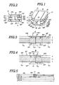
- an embodiment of magnetic head 10 comprises a main head block 12 and side head blocks 14 and 16 provided on respective sides of the main head block 12. Respective shielding plates 18 and 20 are interposed between the main head block 12 and the side head blocks 14 and 16.
- the side head block 14 comprises three sub-blocks 141, 142 and 143 stacked on each other, and each formed of a magnetically conductive material, such as permalloy. Respective shielding plates 144 and 145 are disposed between the sub-blocks 141 and 142, and 142 and 143 to form magnetic shields.
- the side head block 16 comprises three sub-blocks 161, 162 and 163 formed of magnetically conductive material, such as permalloy. Respective shielding plates 164 and 165 are inserted between the sub-blocks 161 and 162, and 162 and 163.
- the main head block 12 is formed with a magnetic gap 121 for recording and reproducing information on a magnetic tape 22 (shown in Figures 3 and 4).
- the sub-blocks 141 and 143 and the sub-blocks 161 and 162 are formed with respective magnetic gaps 146, 147, 166 and 167.
- the magnetic gap 121 in the main head block 12 will be referred to as the primary magnetic gap, and the magnetic gaps 146, 147, 166 and 167 formed in the side head blocks 14 and 16 will be referred to as the auxiliary magnetic gaps.
- the primary magnetic gap 121 extends transversely to the tape driving direction and is located at the middle of the magnetic head block 12.
- each of the auxiliary magnetic gaps 146, 147, 166 and 167 extends transversely to the tape driving direction across the associated sub-block 141, 143, 161 or 163.
- the length of the primary magnetic gap 121 is D1
- the distance between the opposing ends of the sub-blocks 141 and 143, and 161 and 163 is D2
- the overall height of the side head blocks 14 and 16 is D3
- these dimensions preferably satisfy the following formula: D3 ⁇ D1>D2
- the length D1 of the primary magnetic gap 121 corresponds to the width W (shown in Figures 3 and 4) of a recording track 221 on the magnetic tape 22.
- auxiliary magnetic gaps 146 and 147 which are located at the trailing side with respect to the primary magnetic gap 121.
- the auxiliary magnetic gaps 146 and 147 thus partially erase information recorded on the associated track 221. Since the auxiliary magnetic gaps 146 and 147 are so related with the primary magnetic gap 121 as to satisfy the formulae (2) and (3), any old signal SO recorded in an earlier recording operation can be successfully erased, even when the magnetic tape position is offset from the magnetic head block 12 by the maximum offset E. Moreover, the portion of the new signal SN, recorded out of the track 221 due to offset of the magnetic tape position, can be successfully erased by the auxiliary magnetic gaps 141 and 143. Therefore, cross-talk in reproducing the new signal SN can be successfully avoided.
- auxiliary magnetic gaps 166 and 167 which are located at the trailing side with respect to the primary magnetic gap 121.
- the auxiliary magnetic gaps 166 and 167 therefore erase portions of the signal recorded on the track 221.
- the old signal SO can be completely erased and also portions of the new signal SN recorded out of the track 221 ca be successfully erased. Therefore, in reverse mode recording also, only the new signal SN is recorded in the track 221.
- the magnetic head 10 is particularly useful in high-density recording.
- Figure 5 shows an example of such use, where a plurality of recording tracks Ch-1, Ch-2, Ch-3 and Ch-4 are provided on the magnetic tape 22.
- the form and operation of the magnetic head block 10 and in particular the fact that in this case the auxiliary magnetic gaps 146 and 147 are slightly offset from the auxiliary magnetic gaps 166 and 167, ensures creation of adequate guard bands in either direction of recording.
- the cartridge 210 is formed in a thin, rectangular-box-shaped configuration, which is compatible with a disc drive for floppy discs of corresponding size, such as 3.5 inch (approximately 89 mm) microfloppy discs of the tape disclosed in US-A-4 445 155.
- a disc drive for floppy discs of corresponding size such as 3.5 inch (approximately 89 mm) microfloppy discs of the tape disclosed in US-A-4 445 155.
- the present invention is applicable to magnetic tape cartridges compatible with disc drives of any size, and to such cartridges using and endless-loop-type tape.
- the magnetic tape 22 is housed within the cartridge 210.
- the cartridge 210 is of substantially the same size and shape as the microfloppy disc cartridge disclosed in US-A-4 445 155, but is longer than that disc cartridge.
- the length of the normal disc cartridge is illustrated by the line D in Figure 6.
- the cartridge 210 has an extra section 211 which accommodates the tape reels, the tape drive mechanism and so forth. When the cartridge 210 is loaded into a disc drive for which it is designed, the extra section 211 will remain outside of the disc drive, protruding from the opening of the disc drive.
- the cartridge 210 is further formed with a projection 210a projecting from the front end of the cartridge 210.
- the projection 210a serves as an indicator for making the disc drive recognize that the cartridge 210 is used.
- the cartridge 210 match the floppy disc cartridge not only in width and thickness, but also in length, if necessary.
- the cartridge 210 has semi-cylindrical hollow extensions 218 and 220 near its rear corners and along its rear edge ('rear" referring to the direction of insertion into the disc drive).
- the extensions 218 and 220 extend upwards from the upper surface of the cartridge 210 and thus define tape reel recesses receiving a supply reel 226 and a take-up reel (not visible).
- a space for a power train, which will be described in detail later, remains between the tape reel recesses.
- the cartridge 210 has recesses 232 exposed to the outside on its upper and lower surfaces respectively. Longitudinally (with respect to the direction of insertion) elongated tape access apertures 236 are formed in the upper and lower surfaces within the recesses 232. The tape access apertures 236 are aligned with each other to allow a disc drive head (not shown) of a disc drive access to the tape 22.
- the disc drive can be the same as or slightly modified from that disclosed in US-A-4 445 155.
- the cartridge 210 also has positioning holes 239 for positioning the cartridge 210 within the disc drive.
- the positioning holes 239 receive positioning pins (not shown) built into the disc drive.
- a sliding shutter (not shown) slidingly engages the recesses 232. Upper and lower surfaces of the shutter lie flush with the upper and lower surfaces of the cartridge 210 as assembled.
- the shutter has longitudinally elongated apertures of the same size and configuration as the tape access apertures 236 of the cartridge 210.
- the shutter is movable between the closed position, in which its apertures are offset from the tape access apertures 236 and the tape 22 is hidden, and the open position, in which its apertures are aligned with the tape access apertures 236 to allow the disc drive head access to the tape 22.
- the sliding shutter is normally biased by a spring (not shown) towards the closed position, and is actuated to the open position when the cartridge 210 is inserted into the disc drive.
- the cartridge 210 also has a central aperture 246.
- a centre core disc 248 is rotatably mounted on a boss extending from the lower surface of the upper portion of the cartridge 210 through a bearing, such as an oil-less metal bearing.
- the centre core disc 248 opposes the central aperture 246 and is thus exposed through the central aperture 246.
- the centre core disc 248 has a centre positioning aperture 250 and a driving and positioning aperture 252.
- the driving and positioning aperture 252 is offset by a given distance from the centre positioning aperture 250.
- the centre positioning aperture 250 is designed to engage a disc drive motor spindle.
- the driving and positioning aperture 252 is designed to engage a driving pin mounted on a turntable of the disc drive which is driven to rotate by the motor spindle. Therefore, the centre core disc 248 is driven to rotate by the driving force transmitted through the turntable of the disc drive.
- a tape run path 262 is defined within the thin space defined in the front portion of the cartridge 210 along which the tape 22 passes between the tape access apertures 236. Tape guides or bars 264 define the tape run path 262.
- the tape run path 262 has a first section 266 near the supply reel 226 and extending longitudinally along one edge of the cartridge 210, a second section 268 near the take-up reel and extending longitudinally along the other edge of the cartridge 210, and a third section 270 extending laterally across the front edge and between the tape access apertures 236.
- tape guides 264 are provided to deflect the tape 22.
- the word 'longitudinal' used in connection with the tape path means the axis of movement along the first and second sections 266 and 268 of the tape run path 262
- the word 'lateral' used in connection with the tape path means the axis of movement along the third section 270 of the tape run path 262.
- leader tape sections 22a are formed adjacent to the tape ends.
- a leader tape section 22a can have a known construction and is optically detectable by means of optical tape end detectors which are provided in the disc drive for automatically stopping tape drive or for automatically reversing the tape driving direction.
- the upper and lower portions of the cartridge 210 have circular transparent sections 272 and 274, for example, holes or portions of transparent resin material, opposing the first and second sections 266 and 268 of the tape run path 262.
- the cartridge 210 is provided with a specially designed tape drive mechanism.
- the take-up reel is driven to extract the tape 22 from the supply reel 226 through the tape run path 262 during recording and reproduction.
- This tape direction will be hereinafter referred to as 'forward'.
- the supply reel 226 must be driven to extract the tape 22 from the take-up reel during rewinding.
- the supply reel 226 drives the tape 22 through the tape run path 262 in the direction opposite to the forward direction. This direction will hereafter be referred to as 'reverse'.
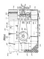
- the tape drive mechanism includes a pair of bevel gear blocks 278 (only one is seen) as shown in Figure 6.
- the bevel gear blocks 278 are generally cylindrical and have bevel gears 280 respectively at one end thereof.
- the bevel gear blocks 278 are coaxially mounted on the mutually opposing axial ends of the supply reel 226 and the take-up reel.
- the bevel gear blocks 278 are rotatable with the supply reel 226 and the take-up reel.
- a pair of intermediate gear blocks 304 and 306 are rotatably supported by gear shafts 308 extending vertically from the floor of the cartridge 210.
- the gear shafts 308 are arranged in lateral alignment at a given distance from each other.
- the distance between the gear shafts 308 is slightly greater than or approximately equal to twice the outer diameter of the intermediate gear blocks 304 and 306.
- the intermediate gear blocks 304 and 306 have bevel gears 320 and 322 respectively at their upper ends. Respective bevel gears 320 and 322 constantly engage the corresponding bevel gears 280.
- the intermediate gear blocks 304 and 306 also have plane gears 324 and 326 below the bevel gears 320 and 322.
- the plane gears 324 and 326 lie in the same horizontal plane at a given distance from each other. Since the gear shafts 308 are separated by a distance slightly greater than or approximately equal to the outer diameter of the intermediate gear blocks 304 and 306, the distance between the plane gears 324 and 326 is slightly greater than the outer diameter thereof.
- a two-way coupling gear 328 is disposed between the plane gears 324 and 326.
- the two-way coupling gear 328 is mounted on a pivotal base 330.
- the pivotal base 330 has a cylindrical base section 332 pivotably mounted at the top of a pivot shaft 334 extending vertically from the floor of the cartridge 210.
- a sleeve bearing is interposed between the inner periphery of the cylindrical base section 332 and the outer periphery of the pivot shaft 334 to allow pivotal movement of the pivotal base 330.
- the pivotal base 330 also has a pivoting arm 338.
- a gear shaft extends downward from the pivoting arm 338. Adjacent to its lower end, this gear shaft carries the two-way coupling gear 328.
- the two-way coupling gear 328 is rotatable about this gear shaft.
- a drive gear block 352 is mounted at the lower end of the pivot shaft 334 through a sleeve bearing.
- the drive gear block 352 has a drive gear 356 constantly engaging the two-way coupling gear 328.
- the drive gear block 352 also has a pulley integrally formed with the drive gear 356. This pulley is connected to a pulley 360 integral with the centre core disc 248 by means of a driving belt 362.
- the gear ratio of the aforementioned tape drive mechanism is selected so as to drive the tape 22 at a speed equal to the rotational speed of a floppy disc on the same disc drive.
- the tape speed at the third section 270 of the tape run path 262 has to be equal to the rotational speed of a floppy disc, so that the disc drive can use the same recording and reproduction operations without adjustment.
- the turntable In order to drive the magnetic tape 22 forward (from the supply reel 226 onto the take-up reel), the turntable is driven clockwise. With clockwise rotation of the turntable, the centre core disc 248 is driven clockwise. The clockwise rotational force is transmitted from the pulley 360 of the centre core disc 248 to the pulley 358 of the drive gear block 152 through the drive belt 362. Therefore, the drive gear 356 is driven to rotate clockwise in Figure 6.
- coil springs serving to restrict rotation of the intermediate gear blocks 304 and 306. Since the bevel gears 320 and 322 of the intermediate gear blocks 304 and 306 are constantly engaged with the bevel gears 280, rotation of the supply reel 226 and the take-up reel is also restricted by means of these coil springs. Therefore, even when release of the cartridge 210 from the turntable of the disc drive is stopped abruptly, slackening of the tape 22 due to over-running of the tape reels is prevented.
- the slip plate maintains frictional engagement with the mating surface of the pivoting arm 338 of the pivotal base 330 due to the spring force of the coil spring as the two-way coupling gear 328 becomes free from the clockwise rotational force of the drive gear 356. Therefore, the counter-clockwise rotational force transmitted by the drive gear 336 of the drive gear block 352 to the two-way coupling gear 328 serves as a driving force for the pivotal base 330, causing the pivotal base 330 to pivot counter-clockwise in Figure 6.
- magnetic tape 22 three-quarters inch (approximately 19 mm) wide is employed in the cartridge 210.
- eighty recording tracks can be formed, which corresponds to the number that can be formed on a 3.5 inch (approximately 89 mm) floppy disc.
- Each track formed on the tape 22 extends longitudinally along the tape 22. It will be appreciated that the length of each track depends solely on the length of the tape 22, and so can be substantially longer than the length of the recording tracks formed on a 3.5 inch (approximately 89 mm) floppy disc.
- the capacity of each track on the tape 22 will be several tens of times greater than that of a track on a floppy disc. If the tape 22 is 12 m long, the capacity of the cartridge 210 will be approximately 20 megabytes.
- one of the leader tape sections 22a of the tape 22 is detected by one of the tape end detectors.
- the tape end detector detecting the leader tape section 22a produces a detector signal for stopping drive of the tape 22 or reversing the tape driving direction.
- a preferred embodiment of the magnetic tape cartridge 210 has the transparent section 272 and 274 formed of a transparent resin material, entry of dust into the cartridge 210 can be prevented. This eliminates or at least significantly reduces the possibility of read/write error resulting from damage to the tape 22. This is very important when utilizing such a cartridge 210 as back-up storage for a computer.
- the present invention is applicable to any of magnetic tape cartridge compatible with disc drives.
Landscapes
- Engineering & Computer Science (AREA)
- Manufacturing & Machinery (AREA)
- Recording Or Reproducing By Magnetic Means (AREA)
- Magnetic Heads (AREA)
Applications Claiming Priority (2)
| Application Number | Priority Date | Filing Date | Title |
|---|---|---|---|
| JP293525/85 | 1985-12-28 | ||
| JP60293525A JPS62157313A (ja) | 1985-12-28 | 1985-12-28 | 往復記録再生ヘツド |
Publications (2)
| Publication Number | Publication Date |
|---|---|
| EP0228903A2 true EP0228903A2 (de) | 1987-07-15 |
| EP0228903A3 EP0228903A3 (de) | 1990-11-14 |
Family
ID=17795866
Family Applications (1)
| Application Number | Title | Priority Date | Filing Date |
|---|---|---|---|
| EP19860310119 Withdrawn EP0228903A3 (de) | 1985-12-28 | 1986-12-23 | Magnetköpfe |
Country Status (4)
| Country | Link |
|---|---|
| EP (1) | EP0228903A3 (de) |
| JP (1) | JPS62157313A (de) |
| KR (1) | KR870006515A (de) |
| BR (1) | BR8606435A (de) |
Cited By (2)
| Publication number | Priority date | Publication date | Assignee | Title |
|---|---|---|---|---|
| EP0232620A3 (de) * | 1985-12-28 | 1988-09-21 | Sony Corporation | Magnetbandkassetten |
| EP0265665A3 (de) * | 1986-10-27 | 1991-02-06 | International Business Machines Corporation | Leseschreibkopf für magnetische Daten auf einer Doppelspur zur Verbesserung von Spur-Falschregistrierungseffekten bei Doppelspur-Vertikalaufzeichnung |
Families Citing this family (1)
| Publication number | Priority date | Publication date | Assignee | Title |
|---|---|---|---|---|
| KR100370766B1 (ko) * | 1995-04-26 | 2003-03-31 | 삼성전자 주식회사 | 하드디스크드라이브의헤드장치 |
Family Cites Families (5)
| Publication number | Priority date | Publication date | Assignee | Title |
|---|---|---|---|---|
| US3614342A (en) * | 1969-06-02 | 1971-10-19 | Ampex | Bidirectional tape transport with reversible head mechanism driven by lapstan motor |
| DE2653345A1 (de) * | 1976-11-24 | 1978-06-01 | Basf Ag | Magnetkopfanordnung zum aufzeichnen/wiedergeben und loeschen von informationen |
| JPS56114118A (en) * | 1980-02-13 | 1981-09-08 | Teac Co | Magnetic recording and reproducing head device |
| JPS59129920A (ja) * | 1983-01-13 | 1984-07-26 | Toshiba Corp | 磁気ヘツド組立体 |
| US4796136A (en) * | 1985-03-18 | 1989-01-03 | Hewlett-Packard Company | Disc drive compatible cartridge tape |
-
1985
- 1985-12-28 JP JP60293525A patent/JPS62157313A/ja active Pending
-
1986
- 1986-12-23 EP EP19860310119 patent/EP0228903A3/de not_active Withdrawn
- 1986-12-24 BR BR8606435A patent/BR8606435A/pt unknown
- 1986-12-27 KR KR860011349A patent/KR870006515A/ko not_active Withdrawn
Cited By (2)
| Publication number | Priority date | Publication date | Assignee | Title |
|---|---|---|---|---|
| EP0232620A3 (de) * | 1985-12-28 | 1988-09-21 | Sony Corporation | Magnetbandkassetten |
| EP0265665A3 (de) * | 1986-10-27 | 1991-02-06 | International Business Machines Corporation | Leseschreibkopf für magnetische Daten auf einer Doppelspur zur Verbesserung von Spur-Falschregistrierungseffekten bei Doppelspur-Vertikalaufzeichnung |
Also Published As
| Publication number | Publication date |
|---|---|
| EP0228903A3 (de) | 1990-11-14 |
| JPS62157313A (ja) | 1987-07-13 |
| BR8606435A (pt) | 1987-10-20 |
| KR870006515A (ko) | 1987-07-11 |
Similar Documents
| Publication | Publication Date | Title |
|---|---|---|
| US6188532B1 (en) | Backward compatible head and head positioning assembly for a linear digital tape drive | |
| EP0035548A1 (de) | Datenkassettenaufzeichnungsgerät mit positioniermechanismus für den kopf. | |
| US4479618A (en) | Tape cassette adapter | |
| EP0195571B1 (de) | Bandkassette | |
| US4779156A (en) | Chucking mechanism for magnetic tape cartridge used with disk drive | |
| JPS6363989B2 (de) | ||
| US6267313B1 (en) | Wide tape cartridge | |
| EP0228904B1 (de) | Magnetbandkassetten | |
| EP0214820B1 (de) | Magnetbandkassette | |
| EP0228903A2 (de) | Magnetköpfe | |
| EP0929071B1 (de) | Mehrfachbandkassette und Laufwerkssytem in dem Bänder aus der Kassette herausgezogen werden | |
| US6343757B1 (en) | Elongated clearance-type guide for magnetic tape | |
| JPS6011559B2 (ja) | 位置決め機構 | |
| US5592351A (en) | Low profile enclosure and mechanism for a single channel head 8mm tape drive | |
| EP1746592A2 (de) | Kassettenlaufwerk mit verbessertem Bandlauf und entsprechende Verfahren | |
| EP0232620A2 (de) | Magnetbandkassetten | |
| EP0837466B1 (de) | Bandantrieb zur Benutzung mit Bandkassetten | |
| EP0219950A2 (de) | Magnetbandkassette | |
| EP0516424B1 (de) | Gerät zum Laden einer Bandkassette | |
| WO1988006793A1 (en) | Magnetic tape backup device for use with a floppy disk drive | |
| EP1282123A2 (de) | Bandträger | |
| JPH054143Y2 (de) | ||
| EP1436811B1 (de) | Magnetbandkassette mit einem datenspeichermedium verbunden mit einem integrierten reinigungsbandabschnitt | |
| US20050035241A1 (en) | Magnetic tape drive | |
| JPS62157385A (ja) | テ−プカセツト |
Legal Events
| Date | Code | Title | Description |
|---|---|---|---|
| PUAI | Public reference made under article 153(3) epc to a published international application that has entered the european phase |
Free format text: ORIGINAL CODE: 0009012 |
|
| AK | Designated contracting states |
Kind code of ref document: A2 Designated state(s): DE FR GB IT |
|
| PUAL | Search report despatched |
Free format text: ORIGINAL CODE: 0009013 |
|
| AK | Designated contracting states |
Kind code of ref document: A3 Designated state(s): DE FR GB IT |
|
| STAA | Information on the status of an ep patent application or granted ep patent |
Free format text: STATUS: THE APPLICATION IS DEEMED TO BE WITHDRAWN |
|
| 18D | Application deemed to be withdrawn |
Effective date: 19910703 |
|
| RIN1 | Information on inventor provided before grant (corrected) |
Inventor name: HENZE, RICHARD H. Inventor name: SPENNER, BRUCE F. Inventor name: CLIFFORD, GEORGE Inventor name: OHTA, TOSHIROC/O PATENTS DIVISION |