EP0228939A1 - Verfahren und Vorrichtung zur mechanischen Bearbeitung von Werkstücken - Google Patents
Verfahren und Vorrichtung zur mechanischen Bearbeitung von Werkstücken Download PDFInfo
- Publication number
- EP0228939A1 EP0228939A1 EP86402668A EP86402668A EP0228939A1 EP 0228939 A1 EP0228939 A1 EP 0228939A1 EP 86402668 A EP86402668 A EP 86402668A EP 86402668 A EP86402668 A EP 86402668A EP 0228939 A1 EP0228939 A1 EP 0228939A1
- Authority
- EP
- European Patent Office
- Prior art keywords
- parts
- tunnel
- gas
- transport gas
- cooled
- Prior art date
- Legal status (The legal status is an assumption and is not a legal conclusion. Google has not performed a legal analysis and makes no representation as to the accuracy of the status listed.)
- Granted
Links
- 238000000034 method Methods 0.000 title claims abstract description 16
- 238000011282 treatment Methods 0.000 title claims description 10
- 239000011236 particulate material Substances 0.000 claims abstract description 8
- 238000007664 blowing Methods 0.000 claims abstract description 3
- 239000000463 material Substances 0.000 claims abstract description 3
- 239000007789 gas Substances 0.000 claims description 38
- IJGRMHOSHXDMSA-UHFFFAOYSA-N Atomic nitrogen Chemical compound N#N IJGRMHOSHXDMSA-UHFFFAOYSA-N 0.000 claims description 19
- 238000005422 blasting Methods 0.000 claims description 17
- 239000007788 liquid Substances 0.000 claims description 11
- 238000001816 cooling Methods 0.000 claims description 10
- 229910052757 nitrogen Inorganic materials 0.000 claims description 9
- 239000007921 spray Substances 0.000 claims description 4
- 238000005507 spraying Methods 0.000 claims description 4
- 239000011248 coating agent Substances 0.000 claims description 3
- 238000000576 coating method Methods 0.000 claims description 3
- 239000002245 particle Substances 0.000 claims description 3
- 239000002826 coolant Substances 0.000 claims 1
- 238000000605 extraction Methods 0.000 claims 1
- 238000011144 upstream manufacturing Methods 0.000 claims 1
- 239000012159 carrier gas Substances 0.000 abstract 1
- 239000004033 plastic Substances 0.000 description 4
- 108010066114 cabin-2 Proteins 0.000 description 3
- 239000002184 metal Substances 0.000 description 3
- 238000005480 shot peening Methods 0.000 description 3
- CURLTUGMZLYLDI-UHFFFAOYSA-N Carbon dioxide Chemical compound O=C=O CURLTUGMZLYLDI-UHFFFAOYSA-N 0.000 description 2
- 239000002131 composite material Substances 0.000 description 2
- 230000000694 effects Effects 0.000 description 2
- 238000005554 pickling Methods 0.000 description 2
- 230000006978 adaptation Effects 0.000 description 1
- 229910002092 carbon dioxide Inorganic materials 0.000 description 1
- 239000001569 carbon dioxide Substances 0.000 description 1
- 239000000110 cooling liquid Substances 0.000 description 1
- 229910001873 dinitrogen Inorganic materials 0.000 description 1
- 230000008030 elimination Effects 0.000 description 1
- 238000003379 elimination reaction Methods 0.000 description 1
- 239000004744 fabric Substances 0.000 description 1
- 238000007710 freezing Methods 0.000 description 1
- 230000008014 freezing Effects 0.000 description 1
- 238000002347 injection Methods 0.000 description 1
- 239000007924 injection Substances 0.000 description 1
- 238000000465 moulding Methods 0.000 description 1
- 230000001105 regulatory effect Effects 0.000 description 1
- 230000035939 shock Effects 0.000 description 1
- 230000008016 vaporization Effects 0.000 description 1
- 238000009834 vaporization Methods 0.000 description 1
Images
Classifications
-
- B—PERFORMING OPERATIONS; TRANSPORTING
- B29—WORKING OF PLASTICS; WORKING OF SUBSTANCES IN A PLASTIC STATE IN GENERAL
- B29C—SHAPING OR JOINING OF PLASTICS; SHAPING OF MATERIAL IN A PLASTIC STATE, NOT OTHERWISE PROVIDED FOR; AFTER-TREATMENT OF THE SHAPED PRODUCTS, e.g. REPAIRING
- B29C37/00—Component parts, details, accessories or auxiliary operations, not covered by group B29C33/00 or B29C35/00
- B29C37/02—Deburring or deflashing
-
- B—PERFORMING OPERATIONS; TRANSPORTING
- B24—GRINDING; POLISHING
- B24C—ABRASIVE OR RELATED BLASTING WITH PARTICULATE MATERIAL
- B24C1/00—Methods for use of abrasive blasting for producing particular effects; Use of auxiliary equipment in connection with such methods
-
- B—PERFORMING OPERATIONS; TRANSPORTING
- B24—GRINDING; POLISHING
- B24C—ABRASIVE OR RELATED BLASTING WITH PARTICULATE MATERIAL
- B24C3/00—Abrasive blasting machines or devices; Plants
-
- B—PERFORMING OPERATIONS; TRANSPORTING
- B24—GRINDING; POLISHING
- B24C—ABRASIVE OR RELATED BLASTING WITH PARTICULATE MATERIAL
- B24C3/00—Abrasive blasting machines or devices; Plants
- B24C3/08—Abrasive blasting machines or devices; Plants essentially adapted for abrasive blasting of travelling stock or travelling workpieces
- B24C3/083—Transfer or feeding devices; Accessories therefor
-
- B—PERFORMING OPERATIONS; TRANSPORTING
- B29—WORKING OF PLASTICS; WORKING OF SUBSTANCES IN A PLASTIC STATE IN GENERAL
- B29C—SHAPING OR JOINING OF PLASTICS; SHAPING OF MATERIAL IN A PLASTIC STATE, NOT OTHERWISE PROVIDED FOR; AFTER-TREATMENT OF THE SHAPED PRODUCTS, e.g. REPAIRING
- B29C35/00—Heating, cooling or curing, e.g. crosslinking or vulcanising; Apparatus therefor
- B29C35/16—Cooling
- B29C2035/1658—Cooling using gas
-
- B—PERFORMING OPERATIONS; TRANSPORTING
- B29—WORKING OF PLASTICS; WORKING OF SUBSTANCES IN A PLASTIC STATE IN GENERAL
- B29K—INDEXING SCHEME ASSOCIATED WITH SUBCLASSES B29B, B29C OR B29D, RELATING TO MOULDING MATERIALS OR TO MATERIALS FOR MOULDS, REINFORCEMENTS, FILLERS OR PREFORMED PARTS, e.g. INSERTS
- B29K2021/00—Use of unspecified rubbers as moulding material
Definitions
- the present invention relates to a process for the mechanical treatment of parts, of the type in which a particulate material is sprayed by blowing, by means of a jet of transport gas, onto the parts to be treated. It applies in particular to the mechanical pickling of parts and to the deburring of molded parts, but also to other mechanical treatments such as the elimination of certain parts of the surface of objects.
- cryogenic processes in which the parts to be treated are first cooled, at least partially, so as to weaken their parts which we want to eliminate by shot blasting (coating or barbs in particular), which considerably facilitates shot blasting.
- shot blasting coating or barbs in particular
- the object of the invention is to make it possible to combine the advantages of the two techniques in question. To this end, it relates to a shot peening process of the aforementioned type, characterized in that at least certain parts of the parts, and / or a coating thereof, are brought to a low embrittlement temperature, and in that that a previously cooled gas is used as the transport gas.
- a gas extracted from a cooling tunnel for the parts to be treated is used as the transport gas.
- the transport gas it is possible to first send the cooled transport gas to the parts, to cool the latter, then introduce the particulate material into the stream of transport cooled.
- the subject of the invention is also an apparatus for mechanical processing of parts intended for the implementation of such a method.
- This device of the type comprising a pipe for circulating a transport gas terminating in a blast spray nozzle, and means for introducing a particulate material into this pipe, is characterized in that it comprises means for supply of cooled transport gas to the pipe.
- the mechanical parts treatment apparatus of the type comprising a tunnel for cooling the parts to be treated and a blasting device or the like, is characterized in that the tunnel is of the type cooled by circulation of a cold gas, and in that the blasting device or the like is arranged outside the tunnel.
- shot-blasting device or the like means any device capable of causing the workpieces to act on a large number of discrete elements, which may not only be particles of shot but also elements which are interconnected in a manner which gives them a certain relative independence as is the case for the ends of the bristles or the blades of a rotary brush.
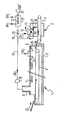
- the apparatus shown in the drawing essentially comprises a cooling tunnel 1 followed by a blasting cabin 2. It is intended for deburring composite parts made of plastic or rubber provided with metal inserts.
- Tunnel 1 is a commercial tunnel of a type used for food freezing. It comprises a thermally insulated envelope 3 containing an endless conveyor 4 which extends over its entire length. This conveyor can for example be made of metallic fabric or made up of plates articulated together.
- the tunnel also includes: - Near its outlet opening 5, nozzles 6 for spraying liquid nitrogen (or, as a variant, another cooling liquid, for example liquid carbon dioxide) oriented obliquely towards the upper wall of the tunnel; - in its intermediate part, fans 7 arranged above the conveyor; and - near its inlet opening 8, a chimney 9 for extracting cold gas connected to the suction of a compressor 10.
- the latter can be provided with a flexible curtain (not shown) made of plastic strips remaining flexible when cold.
- the blasting cabin 2 is traversed by a second endless conveyor 11 and comprises at least one jet blasting machine 12 gaseous.
- the latter comprises a hopper 13 for storing a particle or shot material, provided at its outlet with a metering device 14 delivering into the shaft of a connector 15 in the form of an inverted T.
- the two horizontal branches of this T are connected one, via a pipe 16, to the discharge of the compressor 10, the other to a flexible pipe 17 which ends in a spray nozzle 18.
- a pipe 19 also connects a pipe 19 for supplying additional cooled air.
- This pipe fitted with a valve 20, passes through a heat exchanger 21 traversed by a nitrogen vaporization coil 22 and is supplied by an air compressor 23.
- Part of the cold gas arriving at the shot blasting machine 12 is derived by a pipe 24 and sent into the hopper 13 to precool the shot.
- the parts to be deburred (not shown) are poured onto the conveyor 1 by an inclined plane 25.
- they are gradually cooled by the vaporized nitrogen circulating against the current.
- the parameters of the cooling are chosen so as on the one hand to guarantee that the parts of these parts to be removed by shot blasting, here their molding barbs, are brought to a temperature below their embrittlement temperature, and on the other hand to avoid any thermal shock liable to cause excessive stresses in composite parts, in particular at the plastic or rubber / metal interfaces, and as a result of cracks and detachments.
- the parts thus cooled are discharged through a second inclined plane 26 of the conveyor 4 onto the conveyor 11 and enter the shot blasting cabin 2. They are subjected there to the abrasive action of the shot projected by the nozzle (s) 18, which can be stationary or manipulated by automatic arms or manually.
- the flow rate of the shot transport gas and the shot rate are chosen so as to ensure the desired intensity of the mechanical effect exerted on the parts.
- the gas flow rate can be regulated in particular by the flow of make-up air supplied through line 19.
- the temperature of the transport gas can be adjusted by the flow and temperature of the make-up air; it is chosen to be low enough to ensure that the parts of the parts to be eliminated remain at a temperature below their embrittlement temperature during shot peening.
- the shot is metallic, it is itself cooled by the cold transport gas. In other cases (for example plastic shot), and even when the shot is metallic, it may be desirable to cool the shot during its stay in the hopper 13 by means of the bypass 24 of the cold gas, as described above. .
- the apparatus described above is very advantageous because it uses on the one hand a conventional cooling tunnel, on the other hand a conventional blasting cabin, with only a few adaptations that are easy to carry out (orientation of the nozzles 6, gas circuit 16, 19). In addition, it makes it possible to obtain excellent results during shot peening with a reduced cost both in terms of investment and use, the frigories of liquid nitrogen being particularly well used.
- This device can be modified in different ways, depending on the treatment to be performed and the nature of the parts to be treated: - If the parts are not too delicate, for example for pickling painted metal objects, the nozzles 6 can be arranged so as to spray liquid nitrogen directly on the parts. - The tunnel 1 can be omitted and the cold gas for transporting the shot be used to cool the parts, especially if they are easy to weaken (for example, for deburring rubber objects, weaken around -20 ° C). In this case, we can start by sending only the cold gas on the parts then, large these are sufficiently cooled, pour the shot into the stream of cold gas. It is then necessary, of course, that the temperature of the cold gas is itself lower than the embrittlement temperature of the parts.
- the cold gas may in particular be compressed air cooled by indirect heat exchange with liquid nitrogen or by direct injection of liquid nitrogen into the pipe carrying it.
- the shot blasting machine 12 can be replaced by one or more shot blasting wheels working at room temperature, in particular for the treatment of large objects. In a way surprisingly, it has been found that results are thus obtained at least cost at least as good as with existing devices comprising a special tunnel incorporating a shot blasting machine which works cold.
Landscapes
- Engineering & Computer Science (AREA)
- Mechanical Engineering (AREA)
- Physics & Mathematics (AREA)
- Thermal Sciences (AREA)
- Processing And Handling Of Plastics And Other Materials For Molding In General (AREA)
- Crushing And Grinding (AREA)
- Disintegrating Or Milling (AREA)
- Electrical Discharge Machining, Electrochemical Machining, And Combined Machining (AREA)
- Processing Of Stones Or Stones Resemblance Materials (AREA)
- Mechanical Treatment Of Semiconductor (AREA)
- Extrusion Moulding Of Plastics Or The Like (AREA)
- Finish Polishing, Edge Sharpening, And Grinding By Specific Grinding Devices (AREA)
Priority Applications (1)
| Application Number | Priority Date | Filing Date | Title |
|---|---|---|---|
| AT86402668T ATE56905T1 (de) | 1985-12-12 | 1986-12-02 | Verfahren und vorrichtung zur mechanischen bearbeitung von werkstuecken. |
Applications Claiming Priority (2)
| Application Number | Priority Date | Filing Date | Title |
|---|---|---|---|
| FR8518393A FR2591520B1 (fr) | 1985-12-12 | 1985-12-12 | Procede et appareil de traitement mecanique de pieces |
| FR8518393 | 1985-12-12 |
Publications (2)
| Publication Number | Publication Date |
|---|---|
| EP0228939A1 true EP0228939A1 (de) | 1987-07-15 |
| EP0228939B1 EP0228939B1 (de) | 1990-09-26 |
Family
ID=9325710
Family Applications (1)
| Application Number | Title | Priority Date | Filing Date |
|---|---|---|---|
| EP86402668A Expired - Lifetime EP0228939B1 (de) | 1985-12-12 | 1986-12-02 | Verfahren und Vorrichtung zur mechanischen Bearbeitung von Werkstücken |
Country Status (8)
| Country | Link |
|---|---|
| EP (1) | EP0228939B1 (de) |
| JP (1) | JPS62140765A (de) |
| AT (1) | ATE56905T1 (de) |
| AU (1) | AU594728B2 (de) |
| BR (1) | BR8606149A (de) |
| DE (1) | DE3674563D1 (de) |
| FR (1) | FR2591520B1 (de) |
| GR (1) | GR3003006T3 (de) |
Cited By (5)
| Publication number | Priority date | Publication date | Assignee | Title |
|---|---|---|---|---|
| EP0335089A3 (de) * | 1988-03-26 | 1990-06-13 | Messer Griesheim Gmbh | Verfahren und Vorrichtung zum Entgraten kälteversprödbarer Formteilen |
| EP0569708A1 (de) * | 1992-04-15 | 1993-11-18 | Air Products And Chemicals, Inc. | Reinigungseinrichtung für harte Oberflächen mittels cryogenen Aerosols |
| EP1034889A3 (de) * | 1999-03-05 | 2000-12-20 | Linde Gas Aktiengesellschaft | Verfahren und Vorrichtung zum Bestrahlen mit Strahlmittel unter Kühlung |
| WO2011026864A3 (en) * | 2009-09-01 | 2011-06-23 | Spanolux N.V.- Div. Balterio | Method of manufacturing a covering panel with a profiled edge |
| CN112895247A (zh) * | 2021-01-23 | 2021-06-04 | 大千科技(天津)有限公司 | 一种应用在塑料生产线上的冷却装置 |
Families Citing this family (3)
| Publication number | Priority date | Publication date | Assignee | Title |
|---|---|---|---|---|
| JP3886295B2 (ja) | 1999-06-15 | 2007-02-28 | 松下冷機株式会社 | 冷凍システムのパワー制御装置およびコンプレッサ |
| JP4891653B2 (ja) * | 2006-05-12 | 2012-03-07 | 大陽日酸株式会社 | ドライアイスのガス搬送機構およびドライアイス噴射装置 |
| JP2014004793A (ja) * | 2012-06-26 | 2014-01-16 | Bridgestone Corp | スピューの除去方法 |
Citations (6)
| Publication number | Priority date | Publication date | Assignee | Title |
|---|---|---|---|---|
| FR1433027A (fr) * | 1965-04-26 | 1966-03-25 | Wheelabrator Corp | Dispositif de refroidissement et d'ébarage de profilés en élastomères et matières synthétiques thermoplastiques |
| FR2174331A5 (de) * | 1972-02-29 | 1973-10-12 | Air Liquide | |
| EP0041797A1 (de) * | 1980-06-05 | 1981-12-16 | Parfloor Limited | Oberflächenbehandlung |
| FR2534513A1 (fr) * | 1982-10-14 | 1984-04-20 | Badische Maschf Gmbh | Procede et dispositif pour refroidir et nettoyer des pieces coulees en metal |
| EP0140856A2 (de) * | 1983-10-28 | 1985-05-08 | Aga Aktiebolag | Tiefsttemperatur-Schleuderstrahlvorrichtung zum Abgraten |
| US4524548A (en) * | 1983-04-22 | 1985-06-25 | Air Products And Chemicals, Inc. | Continuous deflashing system |
-
1985
- 1985-12-12 FR FR8518393A patent/FR2591520B1/fr not_active Expired
-
1986
- 1986-12-02 AT AT86402668T patent/ATE56905T1/de not_active IP Right Cessation
- 1986-12-02 DE DE8686402668T patent/DE3674563D1/de not_active Expired - Lifetime
- 1986-12-02 EP EP86402668A patent/EP0228939B1/de not_active Expired - Lifetime
- 1986-12-11 BR BR8606149A patent/BR8606149A/pt unknown
- 1986-12-12 JP JP61295104A patent/JPS62140765A/ja active Pending
- 1986-12-12 AU AU66467/86A patent/AU594728B2/en not_active Ceased
-
1990
- 1990-09-27 GR GR90400337T patent/GR3003006T3/el unknown
Patent Citations (6)
| Publication number | Priority date | Publication date | Assignee | Title |
|---|---|---|---|---|
| FR1433027A (fr) * | 1965-04-26 | 1966-03-25 | Wheelabrator Corp | Dispositif de refroidissement et d'ébarage de profilés en élastomères et matières synthétiques thermoplastiques |
| FR2174331A5 (de) * | 1972-02-29 | 1973-10-12 | Air Liquide | |
| EP0041797A1 (de) * | 1980-06-05 | 1981-12-16 | Parfloor Limited | Oberflächenbehandlung |
| FR2534513A1 (fr) * | 1982-10-14 | 1984-04-20 | Badische Maschf Gmbh | Procede et dispositif pour refroidir et nettoyer des pieces coulees en metal |
| US4524548A (en) * | 1983-04-22 | 1985-06-25 | Air Products And Chemicals, Inc. | Continuous deflashing system |
| EP0140856A2 (de) * | 1983-10-28 | 1985-05-08 | Aga Aktiebolag | Tiefsttemperatur-Schleuderstrahlvorrichtung zum Abgraten |
Cited By (7)
| Publication number | Priority date | Publication date | Assignee | Title |
|---|---|---|---|---|
| EP0335089A3 (de) * | 1988-03-26 | 1990-06-13 | Messer Griesheim Gmbh | Verfahren und Vorrichtung zum Entgraten kälteversprödbarer Formteilen |
| EP0569708A1 (de) * | 1992-04-15 | 1993-11-18 | Air Products And Chemicals, Inc. | Reinigungseinrichtung für harte Oberflächen mittels cryogenen Aerosols |
| EP1034889A3 (de) * | 1999-03-05 | 2000-12-20 | Linde Gas Aktiengesellschaft | Verfahren und Vorrichtung zum Bestrahlen mit Strahlmittel unter Kühlung |
| WO2011026864A3 (en) * | 2009-09-01 | 2011-06-23 | Spanolux N.V.- Div. Balterio | Method of manufacturing a covering panel with a profiled edge |
| CN102596490A (zh) * | 2009-09-01 | 2012-07-18 | 巴尔特利奥-斯巴诺吕克斯股份公司 | 具有轮廓边的覆盖板的制造方法 |
| CN112895247A (zh) * | 2021-01-23 | 2021-06-04 | 大千科技(天津)有限公司 | 一种应用在塑料生产线上的冷却装置 |
| CN112895247B (zh) * | 2021-01-23 | 2022-04-05 | 大千科技(天津)有限公司 | 一种应用在塑料生产线上的冷却装置 |
Also Published As
| Publication number | Publication date |
|---|---|
| ATE56905T1 (de) | 1990-10-15 |
| DE3674563D1 (de) | 1990-10-31 |
| FR2591520A1 (fr) | 1987-06-19 |
| BR8606149A (pt) | 1987-09-22 |
| AU6646786A (en) | 1987-06-18 |
| JPS62140765A (ja) | 1987-06-24 |
| AU594728B2 (en) | 1990-03-15 |
| GR3003006T3 (en) | 1993-02-17 |
| FR2591520B1 (fr) | 1989-06-02 |
| EP0228939B1 (de) | 1990-09-26 |
Similar Documents
| Publication | Publication Date | Title |
|---|---|---|
| US2996846A (en) | Method and means for deflashing or trimming molded rubber parts | |
| US6659844B2 (en) | Pliant coating stripping | |
| US3702519A (en) | Method for the removal of unwanted portions of an article by spraying with high velocity dry ice particles | |
| JPS60156582A (ja) | 結合されたコ−テイングの除去方法 | |
| CA1315108C (fr) | Procede, installation et buse de projection, pour le traitement de pieces par soufflage de grenaille | |
| US20110104993A1 (en) | Blast celaning method and method and device for producing solid carbon dioxide to be used for the same | |
| US3137101A (en) | Method and apparatus for deflashing parts | |
| US10207391B2 (en) | Dry ice parts finishing system | |
| EP0228939B1 (de) | Verfahren und Vorrichtung zur mechanischen Bearbeitung von Werkstücken | |
| JP6872499B2 (ja) | ジェットエンジンを洗浄するための方法および装置 | |
| CN108526141A (zh) | 一种用于底材喷涂前处理的二氧化碳雪花清洗系统 | |
| US8137765B2 (en) | Method of producing alloyed iron article | |
| EP2473318B1 (de) | Rohrisolierung einer arbeitsanlage mit kryogenen flüssigkeitsstrahlen | |
| US10391525B2 (en) | Washing method and apparatus for removing contaminations from article | |
| FR2472433A1 (fr) | Procede et appareil pour la preparation, en particulier le refroidissement et le melange du sable de moulage | |
| CN212077108U (zh) | 一种配件加工用正火热处理装置 | |
| JP2004223410A (ja) | ドライアイスブラスト洗浄装置 | |
| JPH0120037B2 (de) | ||
| JP2019027298A5 (de) | ||
| FR2486637A1 (fr) | Refrigerateur a tunnel pour materiau en pieces | |
| JPH0243730A (ja) | 半導体ウエハの洗浄装置 | |
| JP2004270015A (ja) | 材料表面の洗浄方法及び洗浄装置 | |
| FR2912072A1 (fr) | Procede de refroidissement et de nettoyage de revetement en cours de depot par projection thermique | |
| JPS6393566A (ja) | 凍結粒噴射装置 | |
| JP2000190224A (ja) | ブラスト装置、ガラス割断装置およびガラス割断用噴射ノズル |
Legal Events
| Date | Code | Title | Description |
|---|---|---|---|
| PUAI | Public reference made under article 153(3) epc to a published international application that has entered the european phase |
Free format text: ORIGINAL CODE: 0009012 |
|
| 17P | Request for examination filed |
Effective date: 19861208 |
|
| AK | Designated contracting states |
Kind code of ref document: A1 Designated state(s): AT BE CH DE ES FR GB GR IT LI LU NL SE |
|
| 17Q | First examination report despatched |
Effective date: 19881223 |
|
| GRAA | (expected) grant |
Free format text: ORIGINAL CODE: 0009210 |
|
| AK | Designated contracting states |
Kind code of ref document: B1 Designated state(s): AT BE CH DE ES FR GB GR IT LI LU NL SE |
|
| PG25 | Lapsed in a contracting state [announced via postgrant information from national office to epo] |
Ref country code: IT Free format text: LAPSE BECAUSE OF FAILURE TO SUBMIT A TRANSLATION OF THE DESCRIPTION OR TO PAY THE FEE WITHIN THE PRE;WARNING: LAPSES OF ITALIAN PATENTS WITH EFFECTIVE DATE BEFORE 2007 MAY HAVE OCCURRED AT ANY TIME BEFORE 2007. THE CORRECT EFFECTIVE DATE MAY BE DIFFERENT FROM THE ONE RECORDED.SCRIBED TIME-LIMIT Effective date: 19900926 Ref country code: AT Effective date: 19900926 Ref country code: GB Effective date: 19900926 Ref country code: NL Effective date: 19900926 |
|
| REF | Corresponds to: |
Ref document number: 56905 Country of ref document: AT Date of ref document: 19901015 Kind code of ref document: T |
|
| REF | Corresponds to: |
Ref document number: 3674563 Country of ref document: DE Date of ref document: 19901031 |
|
| PGFP | Annual fee paid to national office [announced via postgrant information from national office to epo] |
Ref country code: GR Payment date: 19901201 Year of fee payment: 5 |
|
| PG25 | Lapsed in a contracting state [announced via postgrant information from national office to epo] |
Ref country code: SE Effective date: 19901203 |
|
| PG25 | Lapsed in a contracting state [announced via postgrant information from national office to epo] |
Ref country code: ES Free format text: LAPSE BECAUSE OF FAILURE TO SUBMIT A TRANSLATION OF THE DESCRIPTION OR TO PAY THE FEE WITHIN THE PRESCRIBED TIME-LIMIT Effective date: 19901227 |
|
| PG25 | Lapsed in a contracting state [announced via postgrant information from national office to epo] |
Ref country code: LI Free format text: LAPSE BECAUSE OF NON-PAYMENT OF DUE FEES Effective date: 19901231 Ref country code: BE Effective date: 19901231 Ref country code: CH Free format text: LAPSE BECAUSE OF NON-PAYMENT OF DUE FEES Effective date: 19901231 Ref country code: LU Free format text: LAPSE BECAUSE OF NON-PAYMENT OF DUE FEES Effective date: 19901231 |
|
| NLV1 | Nl: lapsed or annulled due to failure to fulfill the requirements of art. 29p and 29m of the patents act | ||
| GBV | Gb: ep patent (uk) treated as always having been void in accordance with gb section 77(7)/1977 [no translation filed] | ||
| BERE | Be: lapsed |
Owner name: S.A. L' AIR LIQUIDE POUR L'ETUDE ET L'EXPLOITATION Effective date: 19901231 |
|
| PLBI | Opposition filed |
Free format text: ORIGINAL CODE: 0009260 |
|
| 26 | Opposition filed |
Opponent name: LINDE AKTIENGESELLSCHAFT, WIESBADEN Effective date: 19910626 |
|
| PG25 | Lapsed in a contracting state [announced via postgrant information from national office to epo] |
Ref country code: FR Effective date: 19910830 |
|
| REG | Reference to a national code |
Ref country code: CH Ref legal event code: PL |
|
| PG25 | Lapsed in a contracting state [announced via postgrant information from national office to epo] |
Ref country code: DE Effective date: 19910903 |
|
| REG | Reference to a national code |
Ref country code: FR Ref legal event code: ST |
|
| RDAG | Patent revoked |
Free format text: ORIGINAL CODE: 0009271 |
|
| STAA | Information on the status of an ep patent application or granted ep patent |
Free format text: STATUS: PATENT REVOKED |
|
| 27W | Patent revoked |
Effective date: 19920220 |
|
| REG | Reference to a national code |
Ref country code: GR Ref legal event code: MF4A Free format text: 3003006 |
|
| EUG | Se: european patent has lapsed |
Ref document number: 86402668.7 Effective date: 19910910 |