EP0228972A2 - Vorrichtung und Verfahren zur Kontrolle des Füllstandes von Pulver in einem Behälter - Google Patents
Vorrichtung und Verfahren zur Kontrolle des Füllstandes von Pulver in einem Behälter Download PDFInfo
- Publication number
- EP0228972A2 EP0228972A2 EP86402975A EP86402975A EP0228972A2 EP 0228972 A2 EP0228972 A2 EP 0228972A2 EP 86402975 A EP86402975 A EP 86402975A EP 86402975 A EP86402975 A EP 86402975A EP 0228972 A2 EP0228972 A2 EP 0228972A2
- Authority
- EP
- European Patent Office
- Prior art keywords
- thermocouple
- powder
- weld
- container
- sheath
- Prior art date
- Legal status (The legal status is an assumption and is not a legal conclusion. Google has not performed a legal analysis and makes no representation as to the accuracy of the status listed.)
- Granted
Links
Images

Classifications
-
- G—PHYSICS
- G01—MEASURING; TESTING
- G01F—MEASURING VOLUME, VOLUME FLOW, MASS FLOW OR LIQUID LEVEL; METERING BY VOLUME
- G01F23/00—Indicating or measuring liquid level or level of fluent solid material, e.g. indicating in terms of volume or indicating by means of an alarm
- G01F23/22—Indicating or measuring liquid level or level of fluent solid material, e.g. indicating in terms of volume or indicating by means of an alarm by measuring physical variables, other than linear dimensions, pressure or weight, dependent on the level to be measured, e.g. by difference of heat transfer of steam or water
Definitions
- the invention relates to a device and a method for monitoring the level of a powder in a container.
- the invention makes it possible to fill a container such as a container with powdered material to a determined level.
- a container such as a container with powdered material to a determined level.
- Such a technical problem is encountered for example in the manufacture of parts by powder metallurgy comprising a phase of compression of this powder in an isostatic enclosure, cold or hot.
- the metal powder is placed in a generally opaque tight sheath, in particular in the case of hot isostatic compression which requires a metal sheath.
- This sheath has at its upper part a small diameter conduit which is filled to the desired level. Then the conduit is closed by crushing and welding so as to ensure a tight closure of the sheath.
- it is necessary to know precisely the level of the powder in the filling duct so that the sealing can be performed as close as possible and above this level so as to avoid the presence of dead volumes after shutter.
- Detection devices using radiation require installation heavy and complex tion comprising a radiation generator, a detector of this radiation, means of display on a cathode screen of the detected signal, etc.
- the detection devices by electrical contact are not applicable for non-conductive powders and are subject to functional deficiencies due to false contacts or short circuits.
- the powders are frequently packed by vibrating the sheath or the container in which they are found. These vibrations disturb the measurements of most of these known devices and reduce their sensitivity.
- thermocouple Also known (GB-A-1 487 673) is a device for measuring the level of a liquid, in particular a molten metal, consisting of a tube open at its lower end and having a hole in its peripheral wall. A first welded junction of a differential thermocouple is located at the open lower end of the tube and a second welded junction of this thermocouple is housed in the hole made in the peripheral wall. A gas stream, for example nitrogen, flows from top to bottom inside the tube.
- this device cannot be applied to the measurement of the level of a powder since the circulation of the gaseous current would blow the powder, which would totally distort the measurement of its level.
- this method does not apply to a measurement made in a vacuum, as it is necessary to carry out, by way of nonlimiting example, when it is desired to measure the level of a powder emerging from a degassing installation. In fact, degassing takes place under a high vacuum. It goes without saying that it is impossible to introduce a gas into this vacuum.
- thermocouple It must be possible to measure the level of the powder while the powder continues to be poured around the thermocouple. The measurement must be performed with good accuracy and the measurement probe must be small.
- a control device which comprises: a differential thermocouple consisting of three wires joined together by two welds, namely an upper weld and an end weld spaced apart from each other according to the length of the thermocouple and of the means for measuring the variations in the voltage delivered by the thermocouple as a function of time in the event of a temperature difference between the upper weld and the end weld. It is characterized in that the thermocouple and the upper hot weld are surrounded by a thermal inertia sheath given over at least part of its height, excluding the vicinity of the first hot weld.
- the sheath by heating on the one hand in contact with the powder, on the other hand by absorbing calories from the thermocouple wires between the two welds, slows down the thermal equilibrium of these welds.
- the control device comprises a sheath which completely surrounds the upper weld as well as most of the length of the thermocouple located between the upper weld and the end weld of the external medium so as to leave expose directly to the outside environment only the end solder and an end section of the thermocouple; said sheath being made of a material which is weakly conductive of heat and being in thermal contact with the wires of the thermocouple and with the upper solder; the diameter of the thermocouple wires being small relative to the outside diameter of the sheath, so that the conduction of heat from the outside atmosphere to the upper weld takes place essentially via the sheath, so that the upper weld perceives slow temperature variations without perceiving rapid temperature variations.
- the two welds are relatively close to each other.
- the flow characteristics of the powder such as its temperature and its dispersion, are not the same at the level of the upper weld and of the end weld.
- a distance of 80 mm between these two welds does not allow sufficient measurement accuracy to be obtained.
- thermocouple having thermal inertia and which surrounds the upper weld. part of the length of the thermocouple provides thermal conduction between the medium outside the probe into which the powder flows and the upper solder.
- the temperature variations of the powder as well as of the external medium arrive at this upper weld with a delay time. This weld perceives slow temperature variations, but not rapid temperature variations.
- the conduction via the wires of the thermocouple is negligible since these have a very small diameter, of the order of one tenth of a millimeter. Heat conduction is therefore essentially carried out via the sheath surrounding the thermocouple.
- the material of the sheath and its dimensions (length, diameter) must therefore be chosen in an appropriate manner in order to obtain a suitable thermal inertia to achieve the envisaged goal.
- the sheath will for example be made of stainless steel.
- the sheath therefore plays the role of a calorie integrator. It collects the heat from the powder when it flows while preventing a grain of powder which strikes the upper weld from causing a measurement disturbance.
- this sheath plays the role of radiator by making it possible to return to thermal equilibrium more quickly. In some cases, it also acts as a thermal shock absorber.
- the invention relates to a method for measuring the level of powdered material in a container.
- This process is characterized by the following stages: - there is a differential thermocouple having its two hot welds in the opening of said container, a sheath insulating said thermocouple from powdered material over at least part of its height including the upper hot weld, said powder is continuously introduced into the opening of the container around the thermocouple while monitoring the output voltage at the terminals of this thermocouple, the continuous introduction of powder is stopped after having successively detected a first voltage peak then a second voltage peak corresponding to a first and a second peak in temperature difference between the two hot welds of the thermocouple, - the container is vibrated so as to pack the powder , - an additional quantity of powder is introduced into the container until a third voltage peak across the thermocouple is detected, - the container is again vibrated so as to pack the powder, - the steps of vibrating the container and of introducing an additional quantity of powder are repeated several times until it is
- the measuring device shown in FIG. 1 comprises a differential thermocouple 2 arranged vertically, for example a thermocouple consisting of a chromel wire and an alumel wire connected by welds, respectively an intermediate hot weld 4 and a weld extreme hot 6 spaced from each other in a vertical direction.
- the chromel-alumel metal pair in fact allows a high sensitivity of the thermocouple, of the order of 40 microvolts per centigrade degree in a temperature range between 20 ° C and 150 ° C.
- the hot solder 6 is located at the end of the thermocouple, and is the lowest point.
- the thermocouple is surrounded by a sheath 8 which has the function of slowing down the bringing into thermal equilibrium between the two welds by its own heating. This heating occurs in two ways: first by absorbing calories from the flow of the powder stream flowing in contact with the sheath and secondly by absorbing the calories transmitted by the thermocouple wire between the end welds 4 and bottom 6.
- This sheath extends over a part at less than the length of the thermocouple.
- the hot solder 6, on the other hand must not be sheathed so as to come into direct contact with the powdered material without thermal barrier during filling.
- the thermal inertia effect of the sheath can be more or less accentuated by varying its length, its thickness and its specific heat.
- the temperature difference between the powder and the thermocouple must be at least 0.5 ° C.
- the sheath 8 is itself surrounded over part of its height by a protective tube 10 to which it is fixed.
- the tube 10 slides in a translation passage 12 constituted by a cylindrical sleeve having a cylindrical axial opening for the tube 10. Seals 14 and 16 provide a seal between the tube 10 and the inlet and the outlet of the passage of translation 12.
- the sheath 10 is connected to an electrical passage 18 by means of a centering ring connector 20.
- the sealed electrical passage 18 ensures the electrical connection of the thermocouple wires with an amplifier which has function of amplifying the extremely weak currents delivered by the thermocouple so that these currents can then be measured and / or recorded.
- the measurement of the voltage delivered by the differential thermocouple can be carried out using any suitable means, for example a voltmeter. However, preferably a means will be used to record the variations in the voltage across the thermocouple, for example a plotter. Any amplifier recorder, for example that which is manufactured and marketed by SEFRAM is suitable for this use.
- the lower part of the translation passage 12 is connected to a bellows 22 by means of re of a centering ring fitting 24 provided with a seal 26.
- the bellows is connected to a chamber 28 for the arrival of the powdered material whose level is to be measured.
- This chamber comprising one or more portholes 34 through which the flow of the powder can be observed is connected to a pipe 30 through which the powder is conveyed.
- a centering ring flange 32 provides the connection between the part 28 and the bellows 22.
- the latter has the function of isolating the part 28 and the parts which are integral with the upper part of the measuring device constituted by the electrical passage, the translational passage and the tube 10 supporting the thermocouple proper, in particular so that the vibrations which allow the packing of the powder, as will be explained later, are not transmitted to the thermocouple.
- the chamber 28 is itself connected by means of a centering ring flange 36 to a part 38 integral with the tube 40. It is noted that the lower end of the thermocouple, and in particular the hot weld 6 of the thermocouple, enters the tube 40 of the container. As noted, the thermocouple is located substantially in the center of the tube 40 so as to leave a passage all around for the powder. It is indeed important that this powder can flow in contact with the sheath 8 which surrounds the thermocouple.
- the powder is brought in via the pipe 30, as shown diagrammatically by the arrow 42.
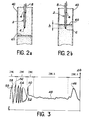
- the powder begins to flow, it causes an increase in the temperature of the hot solder 6, since, as we 'has mentioned above, it is necessary that there is a temperature difference between the powdered material and the thermocouple.
- the hot weld 4 which is protected by the sheath 8, undergoes only a slight and slow rise in temperature (FIG. 2a).
- FOG. 2a The hot weld 4 and the weld 6 corresponding to the temperature difference between these two welds.
- This temperature peak 46 was recorded in zone A of FIG. 3 which represents, on a plotter, the temperature difference between the hot solders as a function of time.
- thermocouple During the period of filling the container, a thermal equilibrium between the two welds is established, by thermal conduction in the chromel and alumel wire of the thermocouple and in the sheath 8. When the two welds are at the same temperature, the potential difference across the thermocouple is canceled. This step corresponds to zone B of the filling phase (reference 48). Slight variations in flow, as well as the high sensitivity of the recorder, cause the appearance of some fluctuations. Indeed, the temperature of the solder 6 is directly related to the average quantity of grains of powder striking per unit of time and of surface the end of the thermocouple, while the temperature of the solder 4 varies much more slowly due to the 'thermal inertia effect of the sheath 8 which protects it.
- This detector therefore also makes it possible to monitor the flow rate during the filling period (zone B).
- zone B When the level of the powder approaches the hot weld 6, reaches it, then slightly exceeds it so that this weld penetrates from a height h inside the powder material (see FIG. 2b), detects a rapid and sudden increase in the temperature of the hot solder 6 without the temperature of the solder 4 changing due to the great thermal inertia which its sheathing gives it 8. This increase in temperature results in a thermal peak 50.
- the return to thermal equilibrium of the two welds of the thermocouple takes place gradually by thermal conduction via the wires of the thermocouple and of the sheath. Most of the filling, corresponding to zones A, B and C is thus completed.
- the container is made to vibrate by means of a vibration device of known type so as to compact the powder, so that the level of the latter drops below the level of the hot solder 6.
- This level 60 is thus found in the position shown diagrammatically in FIG. 2a.
- An additional quantity of powder is then poured until the appearance of a third temperature peak 52 (zone D) is detected.
- the filling is then stopped and the powder is again cup by vibrating the container.
- the level of the powder then drops below the hot solder 6.
- a new quantity of powder is poured through the pipe 30 until the peak 54 is detected. The continuation of these operations is repeated several times. The intermittent addition of small quantities of powder tends to optimize filling.
- the speed of descent of the powder level as a result of tamping becomes progressively lower as the powder located in the container becomes more compacted. This results in spacing and widening of the successive temperature peaks 56, 58, as can be seen in zone E.
- the filling is when the step 59 can be determined. This step appears because the powder vibrates but settles more slowly. During the duration of the landing following the setback, it comes back into contact with the end of the thermocouple at each vibration and therefore slows down the thermal equilibrium of the two welds by adding heat to the lower weld.
- thermocouple When the packing of the powder in the container is satisfactory, the thermocouple is raised by sliding it in the translation passage 12. The two welds 4 and 6 thus regain their thermal equilibrium.
- thermocouple is lowered vertically.
- the temperature of the solder 6 varies instantaneously while the temperature of the upper solder 4 practically does not change due to the thermal inertia imparted by the sheath 8. This temperature difference results in a very sharp peak.
- the position of the powder level is detected with an accuracy of the order of ⁇ 3 mm.
- a measuring device was produced in accordance with the invention comprising a stainless steel sheath 1 mm thick.
- the distance between the two welds is 40 mm and the sheath covers the thermocouple over a distance of 30 mm between these two welds.
- the free distance from the thermocouple which is not covered by the sheath is 10 mm.
Landscapes
- Physics & Mathematics (AREA)
- Thermal Sciences (AREA)
- Fluid Mechanics (AREA)
- General Physics & Mathematics (AREA)
- Control Of Non-Electrical Variables (AREA)
- Investigating Or Analyzing Materials Using Thermal Means (AREA)
- Basic Packing Technique (AREA)
Priority Applications (1)
| Application Number | Priority Date | Filing Date | Title |
|---|---|---|---|
| AT86402975T ATE86729T1 (de) | 1986-01-02 | 1986-12-31 | Vorrichtung und verfahren zur kontrolle des fuellstandes von pulver in einem behaelter. |
Applications Claiming Priority (2)
| Application Number | Priority Date | Filing Date | Title |
|---|---|---|---|
| FR8600021 | 1986-01-02 | ||
| FR8600021A FR2592480B1 (fr) | 1986-01-02 | 1986-01-02 | Dispositif et procede de controle du niveau d'une poudre dans un recipient. |
Publications (3)
| Publication Number | Publication Date |
|---|---|
| EP0228972A2 true EP0228972A2 (de) | 1987-07-15 |
| EP0228972A3 EP0228972A3 (en) | 1989-11-23 |
| EP0228972B1 EP0228972B1 (de) | 1993-03-10 |
Family
ID=9330809
Family Applications (1)
| Application Number | Title | Priority Date | Filing Date |
|---|---|---|---|
| EP86402975A Expired - Lifetime EP0228972B1 (de) | 1986-01-02 | 1986-12-31 | Vorrichtung und Verfahren zur Kontrolle des Füllstandes von Pulver in einem Behälter |
Country Status (4)
| Country | Link |
|---|---|
| EP (1) | EP0228972B1 (de) |
| AT (1) | ATE86729T1 (de) |
| DE (1) | DE3687963D1 (de) |
| FR (1) | FR2592480B1 (de) |
Cited By (2)
| Publication number | Priority date | Publication date | Assignee | Title |
|---|---|---|---|---|
| DE3722667A1 (de) * | 1987-07-09 | 1987-10-29 | Gok Gmbh & Co Kg | Gasentnahmeventil fuer fluessiggasbehaelter |
| EP0541274A1 (de) * | 1991-11-08 | 1993-05-12 | The Boc Group, Inc. | Grenz-Füllstandssensor |
Family Cites Families (7)
| Publication number | Priority date | Publication date | Assignee | Title |
|---|---|---|---|---|
| US1650986A (en) * | 1921-11-28 | 1927-11-29 | Sinclair Refining Co | Level indicator or telltale for oil stills and the like |
| US1833112A (en) * | 1925-07-09 | 1931-11-24 | Brown Instr Co | Thermoelectric liquid level indicator |
| US2279043A (en) * | 1939-06-30 | 1942-04-07 | Standard Oil Dev Co | Fluid level device |
| US2702476A (en) * | 1950-12-26 | 1955-02-22 | Phillips Petroleum Co | Apparatus for measuring liquid level |
| FR1358911A (fr) * | 1963-06-10 | 1964-04-17 | Zd Y Vitezneho Unora Narodni P | Procédé et sonde électrique pour la mesure du niveau de matières ou de liquides,dans des endroits fermés ou difficilement accessibles |
| GB1487673A (en) * | 1975-08-12 | 1977-10-05 | Standard Telephones Cables Ltd | Melt level sensor |
| JPS5764115A (en) * | 1980-10-07 | 1982-04-19 | Japan Atom Energy Res Inst | Method and apparatus detecting liquid level |
-
1986
- 1986-01-02 FR FR8600021A patent/FR2592480B1/fr not_active Expired - Lifetime
- 1986-12-31 AT AT86402975T patent/ATE86729T1/de not_active IP Right Cessation
- 1986-12-31 DE DE8686402975T patent/DE3687963D1/de not_active Expired - Lifetime
- 1986-12-31 EP EP86402975A patent/EP0228972B1/de not_active Expired - Lifetime
Cited By (2)
| Publication number | Priority date | Publication date | Assignee | Title |
|---|---|---|---|---|
| DE3722667A1 (de) * | 1987-07-09 | 1987-10-29 | Gok Gmbh & Co Kg | Gasentnahmeventil fuer fluessiggasbehaelter |
| EP0541274A1 (de) * | 1991-11-08 | 1993-05-12 | The Boc Group, Inc. | Grenz-Füllstandssensor |
Also Published As
| Publication number | Publication date |
|---|---|
| FR2592480A1 (fr) | 1987-07-03 |
| FR2592480B1 (fr) | 1992-10-09 |
| ATE86729T1 (de) | 1993-03-15 |
| EP0228972B1 (de) | 1993-03-10 |
| EP0228972A3 (en) | 1989-11-23 |
| DE3687963D1 (de) | 1993-04-15 |
Similar Documents
| Publication | Publication Date | Title |
|---|---|---|
| EP0939292B1 (de) | Vorrichtung und Verfahren zur kontinuierlichen Messung der Wandabnutzung eines metallischen Behälters | |
| EP2877819B1 (de) | Verfahren und vorrichtung zur messung des gehaltes an gusseisen und schlacke in einem hochofen | |
| FR2822542A1 (fr) | Capteur de temperature et procede pour sa fabrication | |
| EP0216694B1 (de) | Vorrichtung zur Echtzeitkontrolle von Schweissungen, insbesondere für nicht direkt beobachtbare Schweissstellen | |
| CA2109338A1 (fr) | Debitmetre volumique a mesure de temps de vol | |
| EP0228972B1 (de) | Vorrichtung und Verfahren zur Kontrolle des Füllstandes von Pulver in einem Behälter | |
| CA2185249A1 (fr) | Dispositif de detection et de surveillance du percement du fond de la cuve d'un reacteur nucleaire comportant au moins un thermocouple | |
| FR2505489A1 (fr) | Systeme de mesure de niveau de liquide | |
| FR2754348A1 (fr) | Appareil pour la determination du point d'eclair d'un produit | |
| FR2794243A1 (fr) | Dispositif de mesure de la concentration en hydrogene dans un melange gazeux | |
| FR2466026A1 (fr) | Procede de mesure d'un flux neutronique continu et appareil pour la mise en oeuvre de ce procede | |
| FR2706610A1 (fr) | Capteur de flux thermique et dispositif de mesure associé. | |
| EP1004884B1 (de) | Gerät und Verfahren zur Erfassung von internen Lichtbogenfehlern in einem metallgekapselten Leiter | |
| WO2004044541A1 (fr) | Dispositif de mesure d'un flux thermique | |
| EP0981657B1 (de) | Vorrichtung zur erstarrung und zur kontinuierlichen überwachung der kristallzüchtung | |
| FR2657693A1 (fr) | Procede de detection par ultrasons de l'apparition d'une phase gazeuse dans une phase liquide contenue dans une enceinte | |
| FR3096134A1 (fr) | Dispositif de mesure des hautes températures adapté à un environnement corrosif métallique et oxyde à l’état liquide | |
| FR2714732A1 (fr) | Dispositif de détermination des paramètres d'écoulement d'un fluide dans une conduite sous pression. | |
| FR2584189A1 (fr) | Procede d'analyse rapide d'un metal fondu et dispositif pour sa mise en oeuvre | |
| FR2473177A1 (fr) | Dispositif pour determiner la teneur en carbone d'un metal en fusion | |
| FR2568227A1 (fr) | Dispositifs de scellement et de surveillance d'un conteneur renfermant notamment de la matiere calogene | |
| EP0064446A1 (de) | Vorrichtung zur Messung der örtlichen Leistungserzeugung in einem Kernreaktor sowie Verfahren zu deren Kalibrierung | |
| Poinsot | Vibration sensors | |
| BE542865A (de) | ||
| FR2504260A1 (fr) | Dispositif de mesure du debit massique d'une matiere solide en particules en suspension dans un fluide de transport |
Legal Events
| Date | Code | Title | Description |
|---|---|---|---|
| PUAI | Public reference made under article 153(3) epc to a published international application that has entered the european phase |
Free format text: ORIGINAL CODE: 0009012 |
|
| AK | Designated contracting states |
Kind code of ref document: A2 Designated state(s): AT DE FR GB IT SE |
|
| PUAL | Search report despatched |
Free format text: ORIGINAL CODE: 0009013 |
|
| AK | Designated contracting states |
Kind code of ref document: A3 Designated state(s): AT DE FR GB IT SE |
|
| 17P | Request for examination filed |
Effective date: 19900507 |
|
| 17Q | First examination report despatched |
Effective date: 19910625 |
|
| GRAA | (expected) grant |
Free format text: ORIGINAL CODE: 0009210 |
|
| AK | Designated contracting states |
Kind code of ref document: B1 Designated state(s): AT DE FR GB IT SE |
|
| PG25 | Lapsed in a contracting state [announced via postgrant information from national office to epo] |
Ref country code: IT Free format text: LAPSE BECAUSE OF FAILURE TO SUBMIT A TRANSLATION OF THE DESCRIPTION OR TO PAY THE FEE WITHIN THE PRESCRIBED TIME-LIMIT;WARNING: LAPSES OF ITALIAN PATENTS WITH EFFECTIVE DATE BEFORE 2007 MAY HAVE OCCURRED AT ANY TIME BEFORE 2007. THE CORRECT EFFECTIVE DATE MAY BE DIFFERENT FROM THE ONE RECORDED. Effective date: 19930310 Ref country code: DE Effective date: 19930310 Ref country code: GB Effective date: 19930310 Ref country code: AT Effective date: 19930310 |
|
| REF | Corresponds to: |
Ref document number: 86729 Country of ref document: AT Date of ref document: 19930315 Kind code of ref document: T |
|
| REF | Corresponds to: |
Ref document number: 3687963 Country of ref document: DE Date of ref document: 19930415 |
|
| GBV | Gb: ep patent (uk) treated as always having been void in accordance with gb section 77(7)/1977 [no translation filed] |
Effective date: 19930310 |
|
| PLBE | No opposition filed within time limit |
Free format text: ORIGINAL CODE: 0009261 |
|
| STAA | Information on the status of an ep patent application or granted ep patent |
Free format text: STATUS: NO OPPOSITION FILED WITHIN TIME LIMIT |
|
| 26N | No opposition filed | ||
| PGFP | Annual fee paid to national office [announced via postgrant information from national office to epo] |
Ref country code: SE Payment date: 19941130 Year of fee payment: 9 |
|
| PGFP | Annual fee paid to national office [announced via postgrant information from national office to epo] |
Ref country code: FR Payment date: 19941228 Year of fee payment: 9 |
|
| EAL | Se: european patent in force in sweden |
Ref document number: 86402975.6 |
|
| PG25 | Lapsed in a contracting state [announced via postgrant information from national office to epo] |
Ref country code: SE Effective date: 19960101 |
|
| PG25 | Lapsed in a contracting state [announced via postgrant information from national office to epo] |
Ref country code: FR Effective date: 19960830 |
|
| EUG | Se: european patent has lapsed |
Ref document number: 86402975.6 |
|
| REG | Reference to a national code |
Ref country code: FR Ref legal event code: ST |