EP0229190B1 - Verfahren zur bearbeitung eines gebietes - Google Patents
Verfahren zur bearbeitung eines gebietes Download PDFInfo
- Publication number
- EP0229190B1 EP0229190B1 EP86904384A EP86904384A EP0229190B1 EP 0229190 B1 EP0229190 B1 EP 0229190B1 EP 86904384 A EP86904384 A EP 86904384A EP 86904384 A EP86904384 A EP 86904384A EP 0229190 B1 EP0229190 B1 EP 0229190B1
- Authority
- EP
- European Patent Office
- Prior art keywords
- area
- centroid
- cutting
- olc
- tool
- Prior art date
- Legal status (The legal status is an assumption and is not a legal conclusion. Google has not performed a legal analysis and makes no representation as to the accuracy of the status listed.)
- Expired - Lifetime
Links
Images



Classifications
-
- G—PHYSICS
- G05—CONTROLLING; REGULATING
- G05B—CONTROL OR REGULATING SYSTEMS IN GENERAL; FUNCTIONAL ELEMENTS OF SUCH SYSTEMS; MONITORING OR TESTING ARRANGEMENTS FOR SUCH SYSTEMS OR ELEMENTS
- G05B19/00—Program-control systems
- G05B19/02—Program-control systems electric
- G05B19/18—Numerical control [NC], i.e. automatically operating machines, in particular machine tools, e.g. in a manufacturing environment, so as to execute positioning, movement or co-ordinated operations by means of program data in numerical form
- G05B19/402—Numerical control [NC], i.e. automatically operating machines, in particular machine tools, e.g. in a manufacturing environment, so as to execute positioning, movement or co-ordinated operations by means of program data in numerical form characterised by control arrangements for positioning, e.g. centring a tool relative to a hole in the workpiece, additional detection means to correct position
-
- G—PHYSICS
- G05—CONTROLLING; REGULATING
- G05B—CONTROL OR REGULATING SYSTEMS IN GENERAL; FUNCTIONAL ELEMENTS OF SUCH SYSTEMS; MONITORING OR TESTING ARRANGEMENTS FOR SUCH SYSTEMS OR ELEMENTS
- G05B19/00—Program-control systems
- G05B19/02—Program-control systems electric
- G05B19/18—Numerical control [NC], i.e. automatically operating machines, in particular machine tools, e.g. in a manufacturing environment, so as to execute positioning, movement or co-ordinated operations by means of program data in numerical form
- G05B19/41—Numerical control [NC], i.e. automatically operating machines, in particular machine tools, e.g. in a manufacturing environment, so as to execute positioning, movement or co-ordinated operations by means of program data in numerical form characterised by interpolation, e.g. the computation of intermediate points between programmed end points to define the path to be followed and the rate of travel along that path
-
- G—PHYSICS
- G05—CONTROLLING; REGULATING
- G05B—CONTROL OR REGULATING SYSTEMS IN GENERAL; FUNCTIONAL ELEMENTS OF SUCH SYSTEMS; MONITORING OR TESTING ARRANGEMENTS FOR SUCH SYSTEMS OR ELEMENTS
- G05B2219/00—Program-control systems
- G05B2219/30—Nc systems
- G05B2219/49—Nc machine tool, till multiple
- G05B2219/49381—Raster, line servo, area machining, cutting, facing
Definitions
- This invention relates to an NC area cutting method and, more particularly, to an NC area cutting method for cutting the interior of a workpiece area bounded by a closed curve.
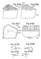
- Forms of numerically controlled machining include cutting in which the interior of an area bounded by a closed curve is hollowed out down to a predetermined depth, and die milling in which the interior of an area is die milled. In such machining, as shown in Fig.
- an area cutting method is conventionally carried out by performing cutting along an (i-1)th cutting path PTi-1 in one direction (the direction of the solid line arrow), raising the tool a predetermined amount at the completion of cutting, then positioning the tool directly above a cutting starting point Ps on the next, or i-th, cutting path PTi, thereafter lowering the tool to the cutting starting point Ps, moving the tool along the i-th cutting path PTi in the direction of the solid line arrow, and subsequently repeating the above unidirectional cutting.
- FIG. 9(B) Another area cutting method shown in Fig. 9(B) includes, following completion of cutting along the cutting path PTi-1 of the (i-1)th cutting path, moving the tool from a cutting end point Pe to the cutting starting point Ps on the next, or i-th, cutting path, and thereafter performing cutting along the i-th cutting path PTi.
- cutting is performed back and forth in the direction of the arrows.
- Still another area cutting method shown in Fig. 9(C) includes obtaining offset paths OFC1, OFC2,... OFCn offset by predetermined amounts with respect to a curve OLC of an external shape, and moving the tool successively along the offset paths.
- the tool must be positioned at the cutting starting point Ps on the i-th cutting path PTi after the completion of cutting along the (i-1)th cutting path PTi-1.
- This method is disadvantageous in that it results in a long tool traveling distance.
- the cutting processes referred to here indicate up cutting and down cutting processes.
- Figs. 10(A), (B) show examples of the down cutting process
- Figs. 10(C), (D) depict examples of the up cutting process.
- a cutting method capable of cutting the workpiece efficiently is selected from the up cutting and down cutting processes.
- the up cutting process [e.g. Fig. 10(A)] and the down cutting process [e.g. Fig. 10(C)] are always mixed, so that cutting cannot be performed efficiently.
- portions are left uncut at, e.g., the central portion of the area, depending upon the contour of the external shape curve.
- This method is disadvantageous in that dealing with these uncut portions is a complicated task.
- a tool path in the form of a spider web pattern is decided within the area and a tool is moved along the tool path to machine the area.
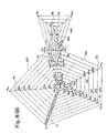
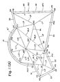
- Figs. 11(A), (B) are views for describing the area cutting method of EP-A-160097. This area cutting method is composed of the following steps:
- area cutting can be carried out while moving the tool continuously. This is advantageous in that it eliminates wasted tool movement and shortens cutting time in comparison with the prior-art method. It also does not leave any uncut portions at, e.g., the central part of the area.
- an NC area cutting method for cutting the interior of a workpiece area bounded by a closed curve, including straight lines, said closed curve being represented by NC data, characterised by comprising: a first step of calculating a centroid of the area bounded by said closed curve; a second step of checking whether said centroid lies inside the area; a third step of checking whether line segments connecting the centroid with respective apices of the area intersect the closed curve if the centroid lies inside the area; a fourth step of partitioning each line segment into a predetermined number of partitions if the centroid lies inside the area and, moreover, none of the line segments intersect the closed curve; and a fifth step of moving a tool along a plurality of closed paths connecting corresponding partitioning points of said line segments.
- the present invention provides an NC area cutting method for cutting the interior of a workpiece area by moving a tool along a plurality of offset paths successively offset in an inward direction from a closed curve specifying the area.
- the centroid of the area is found and a check is performed as to whether the centroid lies inside the area. It is also checked whether line segments connecting the centroid with the apices of the area intersect the closed curve.
- each line segment is partitioned into a predetermined number of partitions and cutting is performed by moving a tool along a plurality of closed paths connecting corresponding partitioning points of the line segments.
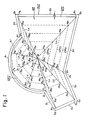
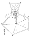
- Fig. 1 is a view for describing the general features of an example of the present invention.
- AR denotes an area
- OLC a closed curve for specifying the area AR
- OFC an offset curve
- W the centroid of the area
- Pi an apex of the area
- Li a line segment connecting the centroid with an apex
- CPT1 - CPTn represent closed paths.
- Fig. 2 is a block diagram of an NC system for practicing the method of the present invention
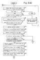
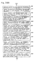
- Fig. 3 is a flowchart of processing. The area cutting method of the present invention will now be described in conjunction with Figs. 1 through 3.
- Area cutting data necessary for area cutting are recorded at appropriate locations on an NC tape or memory (assumed to be an NC tape hereafter) 101.
- area cutting instructions in addition to ordinary numerical control data, area cutting instructions, coordinate values (x j ,y j ) of the apices Q1 - Q10 of the area, the radius rj of a circular arc, finishing margin t, cut-in pitch P, cutting velocity fc, and data for identifying the end of the area cutting data, are recorded on the NC tape 101.
- the area is specified by Xx 1 Yy 1 R0; Xx 2 Yy 2 R0; Xx 3 Yy 3 R 0; Xx 4 Yy 4 R 0; Xx 5 Yy 5 R 0; Xx 6 Yy 6 R 0; Xx 7 Yy 7 R r;
- the processor 103 obtains numerical data (incremental values between an initial position and the starting point W1) for making the tool approach the starting point W1 from the initial position, and thereafter executes ordinary path control using the incremental values.
- the processor 103 moves the tool to the point Q11, then moves the tool along the first closed path LP1 in a cutting feed mode and thereafter moves the tool successively along LP2, LP3, .. LP5, CPo, CP1, CP2, .. CP3 in a similar manner to perform cutting.
- the tool movement sequence is LP1 ⁇ LP2 ... LP5 ⁇ CPo ⁇ CP1 ⁇ CP2 ⁇ CP3 when performing cutting, it is permissible for the sequence to be reversed.
- the present invention is not limited to the illustrated embodiment. It is possible to adopt an arrangement wherein an NC tape (NC data) containing tool path data for area cutting is prepared through the above-described method and the NC data are fed into an NC unit to cut the area.
- NC tape NC data
- NC data NC data
- a check is performed to determine whether the area should be divided into a plurality of convex polygons. If division is not necessary, tool paths in the form of a spider web pattern are decided without dividing the area and cutting is performed by moving the tool along the paths. As a result, processing for deciding the paths is facilitated and the time needed for deciding the paths and for machining can be shortened.
Landscapes
- Engineering & Computer Science (AREA)
- Human Computer Interaction (AREA)
- Manufacturing & Machinery (AREA)
- Physics & Mathematics (AREA)
- General Physics & Mathematics (AREA)
- Automation & Control Theory (AREA)
- Computing Systems (AREA)
- Theoretical Computer Science (AREA)
- Numerical Control (AREA)
Claims (4)
- Gebietsausarbeitungs-Verfahren, das mittels numerischer Steuerung (NC) durchgeführt wird, zum Ausarbeiten des Inneren eines Werkstückgebietes (AR), das durch eine geschlossene Kurve (OLC), die Geraden enthält, umgeben ist, wobei die geschlossene Kurve (OLC) durch NC-Daten repräsentiert ist, gekennzeichnet durch
einen ersten Schritt zum Berechnen eines Flächenschwerpunkts (W) des Gebietes (AR), das durch die geschlossene Kurve (OLC) umgeben ist,
einen zweiten Schritt zum Prüfen, ob der Flächenschwerpunkt (W) innerhalb des Gebietes (AR) liegt,
einen dritten Schritt zum Prüfen, ob Liniensegmente (Li), die den Flächenschwerpunkt (W) mit betreffenden Scheitelpunkten (Pi) des Gebietes verbinden, die geschlossene Kurve (OLC) durchschneiden, wenn der Flächenschwerpunkt (W) innerhalb des Gebietes (AR liegt,
einen vierten Schritt zum Unterteilen jedes Liniensegments (Li) in eine vorbestimmte Anzahl von Teilen, wenn der Flächenschwerpunkt (W) innerhalb des Gebietes (AR) liegt und darüber hinaus keines der Liniensegmente (Pi) die geschlossene Kurve (OLC) durchschneidet, und
einen fünften Schritt zum Bewegen eines Werkzeugs längs einer Vielzahl von geschlossenen Wegen, die entsprechende Unterteilungspunkte der Liniensegmente (Li) verbinden. - Gebietsausarbeitungs-Verfahren nach Anspruch 1, dadurch gekennzeichnet, daß der zweite Schritt umfaßt:
einen Schritt zum Abschätzen der Summe von Winkeln PiWPi+1
einen Schritt zum Entscheiden, daß der Flächenschwerpunkt (W) außerhalb des Gebietes (AR) liegt, wenn a=0 gilt und innerhalb des Gebietes (AR) liegt, wenn a=2π gilt. - Gebietsausarbeitungs-Verfahren nach Anspruch 1 oder 2, dadurch gekennzeichnet, daß der dritte Schritt umfaßt:
einen Schritt zum Prüfen des Vorzeichens eines Winkels <PiWPi+1 (i = 1, 2, ... n), wenn ein Winkel im Uhrzeigersinne positiv oder negativ ist, wobei der Flächenschwerpunkt dieses Gebietes (AR) durch W repräsentiert ist und die Scheitelpunkte des Gebietes (AR) aufeinanderfolgend durch P1, P2, P3, ... Pn repräsentiert sind, und
einen Schritt zum Entscheiden, daß Liniensegmente nicht die geschlossene Kurve (OLC) durchschneiden, wenn alle Vorzeichen dieselben sind, und daß ein Liniensegment die geschlossene Kurve (OLC) durchschneidet, wenn ein Vorzeichen unterschiedlich ist. - Gebietsausarbeitungs-Verfahren nach Anspruch 1, das ferner einen sechsten Schritt umfaßt zum Gewinnen von Werkzeugwegen auf das Teilen des Gebietes (AR) hin in eine Vielzahl von konvexen Polygonen in einem Fall, in dem der Flächenschwerpunkt (W) außerhalb der geschlossenen Kurve (OLC) liegt, oder in einem Fall, in dem irgendeines der Liniensegmente (Li), das den Flächenschwerpunkt (W) mit den Scheitelpunkten (Pi) des Gebietes (AR) verbindet, die geschlossen Kurve (OLC) selbst dann durchschneidet, wenn der Flächenschwerpunkt (W) innerhalb des Gebietes (AR) liegt.
Applications Claiming Priority (2)
| Application Number | Priority Date | Filing Date | Title |
|---|---|---|---|
| JP60157927A JPS6219908A (ja) | 1985-07-17 | 1985-07-17 | 領域加工方法 |
| JP157927/85 | 1985-07-17 |
Publications (3)
| Publication Number | Publication Date |
|---|---|
| EP0229190A1 EP0229190A1 (de) | 1987-07-22 |
| EP0229190A4 EP0229190A4 (de) | 1989-12-19 |
| EP0229190B1 true EP0229190B1 (de) | 1993-03-31 |
Family
ID=15660510
Family Applications (1)
| Application Number | Title | Priority Date | Filing Date |
|---|---|---|---|
| EP86904384A Expired - Lifetime EP0229190B1 (de) | 1985-07-17 | 1986-07-17 | Verfahren zur bearbeitung eines gebietes |
Country Status (6)
| Country | Link |
|---|---|
| US (1) | US4791576A (de) |
| EP (1) | EP0229190B1 (de) |
| JP (1) | JPS6219908A (de) |
| KR (1) | KR900007161B1 (de) |
| DE (1) | DE3688187T2 (de) |
| WO (1) | WO1987000649A1 (de) |
Families Citing this family (14)
| Publication number | Priority date | Publication date | Assignee | Title |
|---|---|---|---|---|
| JPH0766290B2 (ja) * | 1986-06-26 | 1995-07-19 | 東芝機械株式会社 | 工具経路生成方法 |
| JP2669822B2 (ja) * | 1987-05-19 | 1997-10-29 | 三洋電機株式会社 | 作業車の作業経路決定装置 |
| JPH0827651B2 (ja) * | 1987-05-19 | 1996-03-21 | 三洋電機株式会社 | 作業車の作業経路決定装置 |
| DE3853268T2 (de) * | 1987-06-24 | 1995-07-06 | Fanuc Ltd | Verfahren zur geschwindigkeitssteuerung einer evolventen-interpolation. |
| JPH0734166B2 (ja) * | 1987-06-26 | 1995-04-12 | 三菱電機株式会社 | 数値制御装置のオフセット形状作成方法 |
| JPH02139166A (ja) * | 1988-11-14 | 1990-05-29 | Chiyuushiyou Kigyo Jigyodan | 金型みがき方法およびその装置 |
| JPH02183304A (ja) * | 1989-01-10 | 1990-07-17 | Fanuc Ltd | 複合曲面切削における複合曲面生成方法 |
| EP0664434B1 (de) * | 1994-01-20 | 1998-09-02 | Kubo, Akio | Gerät zum Ermitteln der Koordinaten des Schwerpunktes einer Figur |
| JP2804711B2 (ja) * | 1994-02-04 | 1998-09-30 | 明郎 久保 | 図形座標作成装置 |
| TW305927B (de) * | 1995-05-31 | 1997-05-21 | Ushikata Mfg Co Ltd | |
| US6311100B1 (en) * | 1998-09-14 | 2001-10-30 | Mass. Institute Of Technology | Tool path generator for computer aided manufacturing |
| US20190196449A1 (en) * | 2016-05-06 | 2019-06-27 | Yunbo ZHANG | Determining manufacturable models |
| CN111223109B (zh) * | 2020-01-03 | 2023-06-06 | 四川新网银行股份有限公司 | 一种复杂的表格图像解析方法 |
| CN117102724B (zh) * | 2023-10-25 | 2024-02-23 | 宁波经纬数控股份有限公司 | 一种多切割头切割路径控制方法及切割设备 |
Family Cites Families (8)
| Publication number | Priority date | Publication date | Assignee | Title |
|---|---|---|---|---|
| JPS5424156B1 (de) * | 1971-02-03 | 1979-08-18 | ||
| DE3113970A1 (de) * | 1981-04-07 | 1982-11-04 | Dr. Johannes Heidenhain Gmbh, 8225 Traunreut | Numerische bahnsteuerung fuer eine werkzeugmaschine |
| JPS6063606A (ja) * | 1983-08-11 | 1985-04-12 | Fanuc Ltd | 多角形の内部領域加工機能を有する数値制御装置 |
| JPS6090653A (ja) * | 1983-10-22 | 1985-05-21 | Fanuc Ltd | 領域加工方法 |
| US4689750A (en) * | 1983-10-31 | 1987-08-25 | Fanuc Ltd | Machine tool method for deciding if a workpiece surface is concave or convex |
| JPS60155342A (ja) * | 1984-01-10 | 1985-08-15 | Fanuc Ltd | 領域加工方法 |
| JPH0663606A (ja) * | 1992-08-19 | 1994-03-08 | Kobe Steel Ltd | 金属箔の圧延方法 |
| JPH0690653A (ja) * | 1992-09-08 | 1994-04-05 | Marutomo:Kk | サンドイッチ状干菓子類の生地成形装置 |
-
1985
- 1985-07-17 JP JP60157927A patent/JPS6219908A/ja active Pending
-
1986
- 1986-07-17 WO PCT/JP1986/000368 patent/WO1987000649A1/ja not_active Ceased
- 1986-07-17 KR KR1019870700230A patent/KR900007161B1/ko not_active Expired
- 1986-07-17 DE DE8686904384T patent/DE3688187T2/de not_active Expired - Fee Related
- 1986-07-17 EP EP86904384A patent/EP0229190B1/de not_active Expired - Lifetime
- 1986-07-17 US US07/036,679 patent/US4791576A/en not_active Expired - Fee Related
Also Published As
| Publication number | Publication date |
|---|---|
| EP0229190A4 (de) | 1989-12-19 |
| US4791576A (en) | 1988-12-13 |
| KR880700339A (ko) | 1988-02-22 |
| DE3688187D1 (de) | 1993-05-06 |
| JPS6219908A (ja) | 1987-01-28 |
| WO1987000649A1 (fr) | 1987-01-29 |
| EP0229190A1 (de) | 1987-07-22 |
| KR900007161B1 (ko) | 1990-09-29 |
| DE3688187T2 (de) | 1993-07-08 |
Similar Documents
| Publication | Publication Date | Title |
|---|---|---|
| EP0160097B1 (de) | Flächenbearbeitungsverfahren | |
| US4791576A (en) | Area cutting method | |
| EP0168501B1 (de) | Flächenbehandlungsverfahren | |
| EP0148279A1 (de) | Verfahren zur herstellung gekrümmter oberflächen | |
| US4823273A (en) | Area cutting method | |
| US4704687A (en) | Method for constructioning tool approach and retraction paths from preset patterns | |
| US4823275A (en) | Area cutting method | |
| EP0144426B1 (de) | Kontrollverfahren der werkzeuginterferenz | |
| EP0282599B1 (de) | Verfahren zur herstellung eines teilprogramms für laserwerkzeugmaschinen | |
| US4905158A (en) | Normal vector computation method | |
| US4870597A (en) | Complex curved surface creation method | |
| EP0215955B1 (de) | Verfahren zur erzeugung kompositgekrümmter flächen | |
| US4855927A (en) | Complex curved surface creation method | |
| US4855926A (en) | Complex curved surface creation method | |
| EP0151187A1 (de) | Verfahren zur bestimmung einer dreidimensionnalen kurve | |
| US4764877A (en) | Surface cutting method | |
| EP0160705B1 (de) | Bearbeitungsverfahren für werkzeugmaschinen | |
| US4764878A (en) | Surface cutting method | |
| US4851986A (en) | Method of creating NC data for complex curved surfaces | |
| EP0124611B1 (de) | Verfahren zur konusbearbeitung mittels schneiddrahtfunkenerosion | |
| SU1321536A1 (ru) | Способ электроэрозионного вырезани проволочным электродом-инструментом |
Legal Events
| Date | Code | Title | Description |
|---|---|---|---|
| PUAI | Public reference made under article 153(3) epc to a published international application that has entered the european phase |
Free format text: ORIGINAL CODE: 0009012 |
|
| 17P | Request for examination filed |
Effective date: 19870327 |
|
| AK | Designated contracting states |
Kind code of ref document: A1 Designated state(s): DE FR GB |
|
| A4 | Supplementary search report drawn up and despatched |
Effective date: 19891219 |
|
| 17Q | First examination report despatched |
Effective date: 19910927 |
|
| GRAA | (expected) grant |
Free format text: ORIGINAL CODE: 0009210 |
|
| AK | Designated contracting states |
Kind code of ref document: B1 Designated state(s): DE FR GB |
|
| PG25 | Lapsed in a contracting state [announced via postgrant information from national office to epo] |
Ref country code: FR Effective date: 19930331 |
|
| REF | Corresponds to: |
Ref document number: 3688187 Country of ref document: DE Date of ref document: 19930506 |
|
| PG25 | Lapsed in a contracting state [announced via postgrant information from national office to epo] |
Ref country code: GB Effective date: 19930717 |
|
| EN | Fr: translation not filed | ||
| PLBE | No opposition filed within time limit |
Free format text: ORIGINAL CODE: 0009261 |
|
| STAA | Information on the status of an ep patent application or granted ep patent |
Free format text: STATUS: NO OPPOSITION FILED WITHIN TIME LIMIT |
|
| GBPC | Gb: european patent ceased through non-payment of renewal fee |
Effective date: 19930717 |
|
| 26N | No opposition filed | ||
| PGFP | Annual fee paid to national office [announced via postgrant information from national office to epo] |
Ref country code: DE Payment date: 19970725 Year of fee payment: 12 |
|
| PG25 | Lapsed in a contracting state [announced via postgrant information from national office to epo] |
Ref country code: DE Free format text: LAPSE BECAUSE OF NON-PAYMENT OF DUE FEES Effective date: 19990501 |