EP0229204B1 - Spritze für medizinische Zwecke - Google Patents
Spritze für medizinische Zwecke Download PDFInfo
- Publication number
- EP0229204B1 EP0229204B1 EP86100315A EP86100315A EP0229204B1 EP 0229204 B1 EP0229204 B1 EP 0229204B1 EP 86100315 A EP86100315 A EP 86100315A EP 86100315 A EP86100315 A EP 86100315A EP 0229204 B1 EP0229204 B1 EP 0229204B1
- Authority
- EP
- European Patent Office
- Prior art keywords
- hollow needle
- cannula
- protection cap
- hollow
- needle protection
- Prior art date
- Legal status (The legal status is an assumption and is not a legal conclusion. Google has not performed a legal analysis and makes no representation as to the accuracy of the status listed.)
- Expired
Links
Images
Classifications
-
- A—HUMAN NECESSITIES
- A61—MEDICAL OR VETERINARY SCIENCE; HYGIENE
- A61M—DEVICES FOR INTRODUCING MEDIA INTO, OR ONTO, THE BODY; DEVICES FOR TRANSDUCING BODY MEDIA OR FOR TAKING MEDIA FROM THE BODY; DEVICES FOR PRODUCING OR ENDING SLEEP OR STUPOR
- A61M5/00—Devices for bringing media into the body in a subcutaneous, intra-vascular or intramuscular way; Accessories therefor, e.g. filling or cleaning devices, arm-rests
- A61M5/178—Syringes
- A61M5/31—Details
- A61M5/32—Needles; Details of needles pertaining to their connection with syringe or hub; Accessories for bringing the needle into, or holding the needle on, the body; Devices for protection of needles
- A61M5/3202—Devices for protection of the needle before use, e.g. caps
-
- A—HUMAN NECESSITIES
- A61—MEDICAL OR VETERINARY SCIENCE; HYGIENE
- A61M—DEVICES FOR INTRODUCING MEDIA INTO, OR ONTO, THE BODY; DEVICES FOR TRANSDUCING BODY MEDIA OR FOR TAKING MEDIA FROM THE BODY; DEVICES FOR PRODUCING OR ENDING SLEEP OR STUPOR
- A61M5/00—Devices for bringing media into the body in a subcutaneous, intra-vascular or intramuscular way; Accessories therefor, e.g. filling or cleaning devices, arm-rests
- A61M5/178—Syringes
- A61M5/31—Details
- A61M2005/3103—Leak prevention means for distal end of syringes, i.e. syringe end for mounting a needle
- A61M2005/3107—Leak prevention means for distal end of syringes, i.e. syringe end for mounting a needle for needles
- A61M2005/3109—Caps sealing the needle bore by use of, e.g. air-hardening adhesive, elastomer or epoxy resin
Definitions
- the invention relates to a syringe for medical purposes with a syringe barrel and syringe plunger displaceable therein and with a cannula protective cap which can be sealingly plugged onto a needle attachment piece which is arranged at the end of the syringe plunger and is provided with an outer collar.
- Syringes of this type which are already completely ready-made, in particular that is already provided with the cannula and, if appropriate, are also already filled with the product, are also referred to as so-called pre-filled syringes.
- pre-filled syringes both the contents of the syringe barrel and the cannula must be kept sterile until use.
- the needle attachment piece is provided with a cone, onto which the cannula protective cap is slid, the needle tip also being inserted into the cannula protective cap, as a result of which the pre-filled syringe is additionally sealed in the area of the cannula tip.
- the cannula protective cap In the automatic manufacture and processing of such pre-filled syringes, in particular during the washing process and the sterilization, the cannula protective cap must be placed sealingly on the needle attachment piece immediately following these processes.
- the cannula protective cap is therefore initially only loosely pushed onto the cone, so that during the cleaning processes, in particular the sterilization with steam, gas or the like, the cannula and, via the cannula tip, the interior of the cannula are also subjected to the sterilization. If the cannula protection cap is already sitting too tightly on the cone, this area can no longer be adequately cleaned due to the sealing that then occurs. If, on the other hand, the cannula protective cap is pushed onto the cone too loosely, it can become detached during transport and especially during evacuation.
- a syringe is already known from US Pat. No. 3,865,236, the cannula protective cap of which is provided with an automatically operating valve.
- This valve is formed by a slot which is arranged in the wall of the cannula protective cap and extends through it and which is normally closed.
- the valve opens under the pressure difference that occurs and thus prevents overpressure inside the cannula protective cap, which could lift it off the needle hub.
- the disadvantage here is that the interior of the cannula protective cap can only be cleaned or sterilized via the narrow valve opening and by maintaining a pressure difference, which is not possible in practice.
- the invention has for its object to provide a syringe of the type mentioned in such a way that it can already be provided with the cannula protective cap as part of an automatic processing before the cleaning and sterilizing process, thereby ensuring that the cannula itself is also subjected to sterilization without, on the other hand, the risk that the cannula protective cap can become detached from the syringe during the processing process.
- the cannula protective cap has two annular grooves arranged one behind the other in the axial direction, each forming a snap fit for the outer collar, of essentially the same diameter, one or more of the space formed between the two annular grooves being on the outside of the Cannula protection cap open out channels extending.
- the progress achieved by the invention consists essentially in that the cannula protective cap is initially only pushed onto the needle hub until the outer collar snaps into the first annular groove in the push-on direction, whereby the inside of the cannula protective cap and thus also the cannula itself over Channels extending outside of the cannula protection cap are connected to the outside with a predetermined, defined cross-sectional area. This also ensures reliable cleaning and sterilization of this area.
- the cannula protection cap cannot fall off during the transportation of the syringes or during the evacuation, because in the latter case the defined and fixed opening cross section of the channels ensures that the gas volume flows out of the cannula protection cap sufficiently quickly.
- the cannula protective cap After sterilization, the cannula protective cap only has to be pushed forward until the outer collar engages in the second annular groove, as a result of which the interior of the cannula protective cap is completely and definitively sealed off from the needle attachment piece. As a result, the reject occurring due to outgoing or poorly fitting cannula protection caps can be significantly reduced during the processing phase. Furthermore, it is now possible for the first time to validate the sterilization of the interior of the cannula protective cap and the cannula itself, whereas until now such detection was not possible due to a missing or uncontrollable gas exchange between the cannula protective cap and the environment.
- the channels are formed by axial grooves which run in the lateral surface of the first annular groove in the push-on direction of the cannula protection cap in the axial direction towards the open end of the cannula protection cap.
- a total of four channels distributed uniformly over the circumference are provided, which on the one hand ensures a sufficient channel cross section and on the other hand ensures an adequate tight fit of the collar in the ring groove.
- the cannula-side end of the needle hub has the shape of a full cone surface that tapers axially towards the cannula, the outer surface of which merges directly into the outer collar.
- the cannula protective cap will consist more or less entirely of elastic material.
- the ring lips upstream of the ring grooves in the plug-on direction of the cannula protection cap are formed from rubber-elastic material, in order to allow sufficient deformability of the ring lips during the plugging on of the cannula protection cap.
- the cannula protective cap tapers in the hollow cone in the area provided for receiving the cannula and adjoins the second annular groove and the length of the hollow cone-shaped area is dimensioned such that the cannula tip just touches the tip of the hollow cone. when the outer collar is snapped into the first ring groove.
- the cannula tip is freely accessible during the washing and sterilization process, so that the inside of the cannula is also included in the cleaning process.
- the mutual distance between the two ring grooves should expediently be at least as large as the length of the wedge-shaped ground end of the cannula tip, so that after the final fitting of the cannula protection cap and engagement of the ring collar in the second ring groove, the cannula tip is completely inserted into the cannula protection cap.
- the syringe shown in the drawing is intended for medical purposes and consists of a syringe barrel 1, only schematically indicated in the drawing, with a syringe plunger 2 that can be displaced therein.
- the syringe is also provided with a cannula protection cap 3, which is attached to a needle attachment piece 4 arranged at the end of the syringe barrel 1 is pluggable sealing.
- the needle hub 4 is provided with an outer collar 5.
- the cannula protective cap 3 has two annular grooves 7, 8 which are arranged one behind the other in their longitudinal axis 6 and each form a snap fit for the outer collar 5 and have essentially the same diameter.
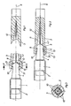
- the cannula protective cap 3 according to FIG. 1 is not completely pushed onto the needle hub 4, so that the outer collar 5 snaps into the first annular groove 7 in the push-on direction of the cannula protective cap 3, the interior 11 of the cannula protective cap 3 stands over the channels 10 with the exterior of the cannula protective cap 3 in connection.
- the cannula protective cap 3 is thus on the one hand already firmly connected to the syringe, on the other hand there is a connection with the cross-sectional area which is precisely determined to the interior of the cannula protective cap 3 and the cannula 12 itself, so that the necessary and desired sterilization can also take place there.
- the cannula protective cap 3 is pushed further onto the needle hub 4 until the outer collar 5 engages in the second annular groove 8 according to FIG. 2 and the connection of the interior 11 of the cannula protective cap 3 to the outside is interrupted. This enables the sterilization of the interior 11 of the cannula protective cap 3 and the cannula 12 to be validated for the first time, and the cannula 12 and the interior of the cannula protective cap 3 can be kept sterile.
- the channels 10 are formed in detail, as can be seen in particular from FIG. 3, by axial grooves which run in the lateral surface of the first annular groove 7 in the plug-on direction of the cannula protection cap 3 in the axial direction towards the open end 3.1 of the cannula protection cap 3.
- the number and size of the axial grooves can largely be chosen as desired and can be adapted to the extent necessary as long as a sufficient snug fit of the outer collar 5 in the first annular groove 7 is ensured.
- a total of four channels are provided, which are evenly distributed over the circumference.
- the end of the needle hub 4 on the cannula side has the shape of a full cone surface 4.1 tapering axially towards the cannula 12.
- the outer surface of this merges directly into the outer collar 5.
- the ring lips 7, 8 in front of the ring grooves 7, 8 in each case in the push-on direction of the cannula protection cap are expediently formed by rubber-elastic material in order to simplify the automatic centering and fitting of the cannula protection cap 3.
- the cannula protective cap 3 is designed in detail so that it tapers in a hollow cone shape in the interior 11 provided for receiving the cannula 12 and adjoining the second annular groove.
- the length of the hollow cone-shaped interior 11 is dimensioned such that the cannula tip just touches the tip of the hollow cone when the outer collar 5 is engaged in the first annular groove 7 according to FIG. 1. This ensures that the interior of the cannula is also included in the course of the cleaning and sterilization process.
- the mutual distance between the two annular grooves 7, 8 should be at least as long as the length of the wedge-shaped ground end of the cannula tip, so that after the cannula protective cap 3 has been pushed on completely, the tip of the cannula 12 penetrates completely into it and thus a complete seal also at the cannula tip he follows.
Landscapes
- Health & Medical Sciences (AREA)
- Vascular Medicine (AREA)
- Engineering & Computer Science (AREA)
- Anesthesiology (AREA)
- Biomedical Technology (AREA)
- Heart & Thoracic Surgery (AREA)
- Hematology (AREA)
- Life Sciences & Earth Sciences (AREA)
- Animal Behavior & Ethology (AREA)
- General Health & Medical Sciences (AREA)
- Public Health (AREA)
- Veterinary Medicine (AREA)
- Infusion, Injection, And Reservoir Apparatuses (AREA)
Description
- Die Erfindung betrifft eine Spritze für medizinische Zwecke mit einem Spritzenzylinder und darin verschiebbarem Spritzenkolben sowie mit einer Kanülenschutzkappe, die auf ein am Spritzenkolben endseitig angeordnetes, mit einem Außenbund versehenes Nadelansatzstück dichtend aufsteckbar ist.
- Spritzen dieser Art, die bereits vollständig fertig konfektioniert, insbes. also bereits mit der Kanüle versehen und gegebenenfalls auch bereits befüllt in den Handel kommen, werden auch als sog. Fertigspritze bezeichnet. Bei solchen Fertigspritzen muß sowohl der Inhalt des Spritzenzylinders wie auch die Kanüle bis zur Andwendung steril gehalten werden. Dazu ist in bisher üblicher Ausführungsform das Nadelansatzstück mit einem Konus versehen, auf welchen die Kanülenschutzkappe aufgeschoben ist, wobei im übrigen die Kanülenspitze in die Kanülenschutzkappe eingestochen ist, wodurch eine zusätzliche Abdichtung der Fertigspritze im Bereich der Kanülenspitze erfolgt.
- Bei der automatischen Herstellung und Verarbeitung solcher Fertigspritzen, insbes. beim Waschvorgang und der Sterilisation muß unmittelbar im Anschluß an diese Vorgänge die Kanülenschutzkappe dichtend auf das Nadelansatzstück aufgesteckt werden. Die Kanülenschutzkappe wird daher zunächst nur lose auf den Konus aufgeschoben, damit während der Reinigungsvorgänge, insbes. der Sterilisation mit Dampf, Gas oder dergl. die Kanüle und über die Kanülenspitze auch der Innenraum der Kanüle ebenso der Sterilisation mit unterworfen werden. Sitzt dabei die Kanülenschutzkappe bereits zu fest auf dem Konus, so kann wegen der dann schon auftretenden Abdichtung keine ausreichende Reinigung dieses Bereichs mehr erfolgen. Ist die Kanülenschutzkappe dagegen zu lose auf den Konus aufgeschoben, so kann sie sich während des Transports und insbesondere bei der Evakuierung ablösen.
- Aus der US-A 3 865 236 ist bereits eine Spritze bekannt, deren Kanülenschutzkappe mit einem selbsttätig arbeitendem Ventil versehen ist. Dieses Ventil ist von einem in der Wand der Kanülenschutzkappe angeordneten und sich durch diese hindurch erstreckenden Schlitz gebildet, der normalerweise geschlossen ist. Während des Sterilisierungsvorgangs, insbes. bei abwechselnder Behandlung mit Dampf und Vakuum, öffnet das Ventil unter der auftretenden Druckdifferenz und verhindert so einen Überdruck im Innern der Kanülenschutzkappe, durch welchen diese vom Nadelansatzstück abgehoben werden könnte. Nachteilig hierbei ist jedoch, daß eine Reinigung bzw. Sterilisation des Innenraums der Kanülenschutzkappe nur über die schmale Ventilöffnung und durch Aufrechterhaltung einer Druckdifferenz erfolgen kann, was in der Praxis nicht möglich ist.
- Der Erfindung liegt die Aufgabe zugrunde, eine Spritze der eingangs genannten Art so auszubilden, daß sie im Rahmen einer automatischen Verarbeitung vor dem Reinigungs- und Sterilisiervorgang bereits mit der Kanülenschutzkappe versehen werden kann, wobei sichergestellt wird, daß auch die Kanüle selbst der Sterilisation unterworfen wird, ohne daß andererseits die Gefahr besteht, daß die Kanülenschutzkappe sich während des -Verarbeitungsprozesses von der Spritze lösen kann.
- Diese Aufgabe wird nach der Erfindung dadurch gelöst, daß die Kanülenschutzkappe zwei in axialer Richtung hintereinander angeordnete, jeweils einen Rastsitz für den Außenbund bildende Ringnuten von im wesentlichen gleichem Durchmesser aufweist, wobei in den zwischen den beiden Ringnuten gebildeten Raum einer oder mehrere sich zur Außenseite der Kanülenschutzkappe hin erstreckende Kanäle münden.
- Der durch die Erfindung erreichte Fortschritt besteht im wesentlichen darin, daß die Kanülenschutzkappe zunächst nur soweit auf das Nadelansatzstück aufgeschoben wird, bis der Außenbund in die in Aufschubrichtung vorgelagerte erste Ringnut einrastet, wodurch das Innere der Kanülenschutzkappe und damit auch die Kanüle selbst über die sich zur Außenseite der Kanülenschutzkappe hin erstreckenden Kanäle mit einer vorgegebenen, definierten Querschnittsfläche mit der Außenseite in Verbindung stehen. Damit ist eine zuverlässige Reinigung und Sterilisation auch dieses Bereiches gewährleistet. Andererseits kann wegen des Rastsitzes die Kanülenschutzkappe weder beim Transport der Spritzen noch beim Evakuieren abfallen, zumal in letzterem Fall der definierte und fest vorgegebene Öffnungsquerschnitt der Kanäle für ein hinreichend schnelles Abströmen des Gasvolumens aus der Kanülenschutzkappe Sorge trägt. Nach erfolgter Sterilisation muß die Kanülenschutzkappe lediglich soweit vorgeschoben werden, bis der Außenbund in die zweite Ringnut greift, wodurch das Innere der Kanülenschutzkappe gegen das Nadelansatzstück vollständig definitiv abgedichtet ist. Im Ergebnis kann somit der durch abgehende oder schlecht sitzende Kanülenschutzkappen auftretende Ausschuß während der Verarbeitungsphase erheblich verringert werden. Ferner ist damit erstmals eine Validierung der Sterilisation des Innenraums der Kanülenschutzkappe sowie der Kanüle selbst möglich, während bisher ein solcher Nachweis aufgrund eines fehlenden oder nicht kontrollierbaren Gasaustausches zwischen der Kanülenschutzkappe und der Umgebung nicht möglich war.
- In einer bevorzugten Ausführungsform der Erfindung sind die Kanäle von Axialnuten gebildet, die in der Mantelfläche der in Aufsteckrichtung der Kanülenschutzkappe ersten Ringnut in axialer Richtung zum offenen Ende der Kanülenschutzkappe hin verlaufen. Zweckmäßigerweise sind hierbei insgesamt vier gleichmäßig über den Umfang verteilt angeordnete Kanäle vorgesehen, wodurch einerseits ein ausreichender Kanalquerschnitt und andererseits ein hinreichender fester Sitz des Ringbundes in der Ringnut gewährleistet ist.
- Um das Aufstecken der Kanülenschutzkappe auf das Nadelansatzstück zu erleichtern, empfiehlt es sich, daß das kanülenseitige Ende des Nadelansatzstücks die Gestalt einer sich axial zur Kanüle, hin verjüngenden Vollkegelfläche besitzt, deren Mantelfläche unmittelbar in den Außenbund übergeht. In der Regel wird die Kanülenschutzkappe mehr oder weniger vollständig aus elastischem Material bestehen. In jedem Fall empfiehlt es sich jedoch, daß die in Aufsteckrichtung der Kanülenschutzkappe den Ringnuten jeweils vorgelagerten Ringlippen von gummielastischem Material gebildet sind, um während des Aufsteckens der Kanülenschutzkappe eine hinreichende Verformbarkeit der Ringlippen zu ermöglichen.
- Weiter empfiehlt es sich im Rahmen der Erfindung, daß die Kanülenschutzkappe in dem zur Aufnahme der Kanüle vorgesehenen, an die zweite Ringnut angrenzenden Bereich sich innenseitig hohlkegelförmig verjüngt und die Länge des hohlkegelförmigen Bereichs so bemessen ist, daß die Kanülenspitze die Spitze des Hohlkegels eben berührt, wenn der Außenbund in die erste Ringnut eingerastet ist. Somit ist die Kanülenspitze während des Wasch- und Sterilisationsvorgangs frei zugänglich, so daß auch das Kanüleninnere in den Reinigungsvorgang mit einbezogen ist. Ferner sollte der gegenseitige Abstand der beiden Ringnuten zweckmäßigerweise wenigstens so groß sein, wie die Länge des keilförmig angeschliffenen Endes der Kanülenspitze, so daß nach dem endgültigen Aufstecken der Kanülenschutzkappe und Einrasten des Ringbundes in die zweite Ringnut die Kanülenspitze vollständig in die Kanülenschutzkappe eingestochen ist.
- Im folgenden wird die Erfindung an einem in der Zeichnung dargestellten Ausführungsbeispiel näher erläutert; es zeigen:
- Fig. 1 den Gegenstand nach der Erfindung in für die Sterilisation vorgesehenem Zustand,
- Fig. 2 den Gegenstand nach Fig. 1, jedoch nach Abschluß der Sterilisation bzw. vor Beginn der Weiterverarbeitung der sterilisierten Objekte,
- Fig. 3 einen Schnitt durch den Gegenstand nach Fig. 1 längs der Linie A-A.
- Die in der Zeichnung dargestellte Spritze ist für medizinische Zwecke vorgesehen und besteht aus einem in der Zeichnung nur schematisch angedeuteten Spritzenzylinder 1 mit einem darin verschiebbaren Spritzenkolben 2. Die Spritze ist ferner mit einer Kanülenschutzkappe 3 versehen, die auf ein am Spritzenzylinder 1 endseitig angeordnetes Nadelansatzstück 4 dichtend aufsteckbar ist.
- Im einzelnen ist das Nadelansatzstück 4 mit einen Außenbund 5 versehen. Die Kanülenschutzkappe 3 weist zwei in ihrer Längsachse 6 hintereinander angeordnete, jeweils einen Rastsitz für den Außenbund 5 bildende Ringnuten 7, 8 auf, die im wesentlichen gleichen Durchmesser besitzen. In den zwischen den beiden Ringnuten 7, 8 gebildeten Raum 9 münden mehrere Kanäle 10, die sich zur Außenseite der Kanülenschutzkappe 3 hin erstrecken.
- Solange die Kanülenschutzkappe 3 gemäß Fig. 1 nicht vollständig auf das Nadelansatzstück 4 aufgeschoben ist, so daß der Außenbund 5 in die in Aufsteckrichtung der Kanülenschutzkappe 3 erste Ringnut 7 einrastet, steht der Innenraum 11 der Kanülenschutzkappe 3 über die Kanäle 10 mit dem Äußeren der Kanülenschutzkappe 3 in Verbindung. Während des automatisch ablaufenden Sterilisationsvorganges ist die Kanülenschutzkappe 3 somit einerseits bereits fest mit der Spritze verbunden, andererseits besteht eine hinsichtlich ihrer Querschnittsfläche genau bestimmte Verbindung zum Innenraum der Kanülenschutzkappe 3 und der Kanüle 12 selbst, so daß auch dort die notwendige und gewünschte Sterilisation erfolgen kann. Nach Abschluß dieser Vorgänge wird die Kanülenschutzkappe 3 weiter auf das Nadelansatzstück 4 aufgeschoben, bis der Außenbund 5 in die zweite Ringnut 8 gemäß Fig. 2 einrastet und dadurch die Verbindung des Innenraums 11 der Kanülenschutzkappe 3 nach außen hin unterbrochen wird. Hierdurch ist erstmals eine Validierung der Sterilisation des Innenraums 11 der Kanülenschutzkappe 3 sowie der Kanüle 12 möglich, und Kanüle 12 sowie Innenraum der Kanülenschutzkappe 3 können steril dicht gehalten werden.
- Die Kanäle 10 sind im einzelnen, wie sich insbes. aus Fig. 3 ergibt, von Axialnuten gebildet, die in der Mantelfläche der in Aufsteckrichtung der Kanülenschutzkappe 3 ersten Ringnut 7 in axialer Richtung zum offenen Ende 3.1 der Kanülenschutzkappe 3 hin verlaufen. Die Anzahl und Größe der Axialnuten kann weitgehend beliebig gewählt sein und insoweit den Erfordernissen angepaßt werden, solange ein ausreichender Rastsitz des Außenbundes 5 in der ersten Ringnut 7 gewährleistet ist. Wie die Fig. 3 erkennen läßt, sind im Ausführungsbeispiel insgesamt vier gleichmäßig über der Umfang verteilt angeordnete Kanäle vorgesehen.
- Um das Aufsetzen der Kanülenschutzkappe 3 auf das Nadelansatzstück 4 zu erleichtern, besitzt das kanülenseitige Ende des Nadelansatzstücks 4 die Gestalt einer sich axial zur Kanüle 12 hin verjüngenden Vollkegelfläche 4.1. Dabei geht deren Mantelfläche unmittelbar in den Außenbund 5 über. Ferner sind auch die in Aufsteckrichtung der Kanülenschutzkappe 3 den Ringnuten 7, 8 jeweils vorgelagerten Ringlippen 13 zweckmäßigerweise von gummielastischem Material gebildet, um das automatische Zentrieren und Aufstecken der Kanülenschutzkappe 3 zu vereinfachen.
- Die Kanülenschutzkappe 3 ist im einzelnen so ausgebildet, daß sie sich in dem zur Aufnahme der Kanüle 12 vorgesehenen, an die zweite Ringnut angrenzenden Innenraum 11 hohlkegelförmig verjüngt. Dabei ist die Länge des hohlkegelförmigen Innenraums 11 so bemessen, daß die Kanülenspitze die Spitze des Hohlkegels eben berührt, wenn der Außenbund 5 entsprechend der Fig. 1 in die erste Ringnut 7 eingerastet ist. Dadurch ist sichergestellt, daß im Verlauf des Reinigungs- und Sterilisationsprozesses auch das Kanüleninnere mit einbezogen wird. Der gegenseitige Abstand der beiden Ringnuten 7, 8 sollte wenigstens so groß sein wie die Länge des keilförmig angeschliffenen Endes der Kanülenspitze, damit nach dem vollständigen Aufschieben der Kanülenschutzkappe 3 die Spitze der Kanüle 12 vollständig in diese eindringt und somit eine vollständinge Abdichtung auch an der Kanülenspitze erfolgt.
Claims (7)
Priority Applications (3)
| Application Number | Priority Date | Filing Date | Title |
|---|---|---|---|
| EP86100315A EP0229204B1 (de) | 1986-01-11 | 1986-01-11 | Spritze für medizinische Zwecke |
| DE8686100315T DE3661591D1 (en) | 1986-01-11 | 1986-01-11 | Medical syringe |
| AT86100315T ATE39620T1 (de) | 1986-01-11 | 1986-01-11 | Spritze fuer medizinische zwecke. |
Applications Claiming Priority (1)
| Application Number | Priority Date | Filing Date | Title |
|---|---|---|---|
| EP86100315A EP0229204B1 (de) | 1986-01-11 | 1986-01-11 | Spritze für medizinische Zwecke |
Publications (2)
| Publication Number | Publication Date |
|---|---|
| EP0229204A1 EP0229204A1 (de) | 1987-07-22 |
| EP0229204B1 true EP0229204B1 (de) | 1989-01-04 |
Family
ID=8194822
Family Applications (1)
| Application Number | Title | Priority Date | Filing Date |
|---|---|---|---|
| EP86100315A Expired EP0229204B1 (de) | 1986-01-11 | 1986-01-11 | Spritze für medizinische Zwecke |
Country Status (3)
| Country | Link |
|---|---|
| EP (1) | EP0229204B1 (de) |
| AT (1) | ATE39620T1 (de) |
| DE (1) | DE3661591D1 (de) |
Families Citing this family (11)
| Publication number | Priority date | Publication date | Assignee | Title |
|---|---|---|---|---|
| US5041099A (en) * | 1988-09-16 | 1991-08-20 | Gelabert Danilo D | Non-reusable syringe and cap therefor |
| SI8912397A (en) * | 1989-12-18 | 1997-08-31 | Tase Lazovski | Injection Syringe with a Shield |
| FR2733687B1 (fr) * | 1995-05-04 | 1997-10-03 | Brunel Marc | Procede de fabrication d'un dispositif d'injection du type pre-rempli renfermant une dose de liquide a injecter, et dispositif d'injection realise |
| DE69925205T2 (de) | 1998-07-31 | 2006-03-09 | Becton, Dickinson And Co. | Nadelschutz für vorgefüllte Spritze |
| FR2816848B1 (fr) * | 2000-11-17 | 2003-06-20 | Rumpler Technologies | Dispositif de protection pour aiguille de seringue |
| FR2899482A1 (fr) | 2006-04-11 | 2007-10-12 | Becton Dickinson France Soc Pa | Dispositif d'injection automatique |
| EP2378342A1 (de) | 2010-04-15 | 2011-10-19 | Mmi Ag | Mikromanipulationssystem mit Schutzvorrichtung für Kapillaren |
| JP5976921B2 (ja) * | 2013-03-15 | 2016-08-24 | テルモ株式会社 | シリンジ用組立体、シリンジ用組立体包装体およびプレフィルドシリンジ |
| CN104602741B (zh) | 2013-03-26 | 2018-10-26 | 泰尔茂株式会社 | 弹性帽以及具备所述弹性帽的注射器用组装体 |
| DE102013112654A1 (de) * | 2013-11-15 | 2015-05-21 | Gerresheimer Regensburg Gmbh | Spritze zur Injektion von flüssigen Substanzen |
| CN108378925B (zh) * | 2018-04-16 | 2024-06-07 | 荣科(苏州)医疗科技有限公司 | 一种克氏针保护套 |
Family Cites Families (6)
| Publication number | Priority date | Publication date | Assignee | Title |
|---|---|---|---|---|
| US3370588A (en) * | 1965-08-18 | 1968-02-27 | Burron Medical Prod Inc | Hypodermic needle guard |
| US3381813A (en) * | 1965-09-07 | 1968-05-07 | Pharmaseal Lab | Hypodermic needle and protector therefor |
| US3865236A (en) * | 1973-03-16 | 1975-02-11 | Becton Dickinson Co | Needle shield |
| DE2929425A1 (de) * | 1979-07-20 | 1981-02-12 | Lothar Kling | Vorrichtung fuer injektionsspritzen zur intramuskulaeren und subentanen injektion |
| JPS5825171A (ja) * | 1981-08-06 | 1983-02-15 | テルモ株式会社 | シリンジ |
| US4430080A (en) * | 1982-06-09 | 1984-02-07 | Becton, Dickinson And Company | Syringe assembly with snap-fit components |
-
1986
- 1986-01-11 EP EP86100315A patent/EP0229204B1/de not_active Expired
- 1986-01-11 AT AT86100315T patent/ATE39620T1/de not_active IP Right Cessation
- 1986-01-11 DE DE8686100315T patent/DE3661591D1/de not_active Expired
Also Published As
| Publication number | Publication date |
|---|---|
| DE3661591D1 (en) | 1989-02-09 |
| ATE39620T1 (de) | 1989-01-15 |
| EP0229204A1 (de) | 1987-07-22 |
Similar Documents
| Publication | Publication Date | Title |
|---|---|---|
| DE2947574C2 (de) | Schlauchkupplung für keimfrei zu haltende Leitungsverbinder | |
| DE3687530T2 (de) | Spritze. | |
| DE3210148C2 (de) | Konnektor | |
| DE3515665C1 (de) | Verschlußstopfen | |
| DE69228485T2 (de) | Zusatzgerät für eine parenterale vorrichtung | |
| EP0287950B1 (de) | Sicherheits-Wegwerfspritze | |
| DE69215922T2 (de) | Übertragungsansclussstück | |
| DE69600166T2 (de) | Luer-Lock-Verschlussstück für medizinische Infusions- oder Transfusionsleitungen | |
| DE2645520C2 (de) | ||
| DE69635595T2 (de) | Vorrichtung zur Dampfsterilisation von Erzeugnissen mit Lumen | |
| EP0766975B1 (de) | Spritze für medizinische Zwecke | |
| DE69317919T2 (de) | Nadelumhüllung | |
| EP0691861B1 (de) | Kanülenschutz für eine injektionsspritze | |
| DE69217261T2 (de) | Apparat zum Lagern und Mischen | |
| DE69808205T2 (de) | Vorrichtung zum Befüllen und zum Verabreichen von Spritzen | |
| DE69723278T2 (de) | Pharmazeutische ampulle | |
| EP0528205A1 (de) | Einführungsschleuse für einen Katheter | |
| DE3417183C2 (de) | ||
| EP0412283A1 (de) | Spritzenzylinder für medizinische Zwecke | |
| DE8817024U1 (de) | Gasdichte Verschlußvorrichtung für die Verbindungsenden von Röhren für biomedizinische Flüssigkeitstransporteinrichtungen insbesondere haemodialytische Ketten, welche mittels Sterilisationsgas sterilisiert sind | |
| EP2230182A2 (de) | Vorrichtung zum Setzen eines Stopfens in einem Spritzenzylinder | |
| DE19938078A1 (de) | Vorrichtung zum Entnehmen eines fertigen Flüssigmedikamentes aus einem mit einer durchstechbaren Membran versehenen Behältnis | |
| EP0229204A1 (de) | Spritze für medizinische Zwecke | |
| DE3100622C2 (de) | ||
| WO2009092430A1 (de) | Spritzensystem und verfahren zu dessen herstellung |
Legal Events
| Date | Code | Title | Description |
|---|---|---|---|
| PUAI | Public reference made under article 153(3) epc to a published international application that has entered the european phase |
Free format text: ORIGINAL CODE: 0009012 |
|
| 17P | Request for examination filed |
Effective date: 19861104 |
|
| AK | Designated contracting states |
Kind code of ref document: A1 Designated state(s): AT BE CH DE FR GB IT LI LU NL SE |
|
| 17Q | First examination report despatched |
Effective date: 19871123 |
|
| GRAA | (expected) grant |
Free format text: ORIGINAL CODE: 0009210 |
|
| AK | Designated contracting states |
Kind code of ref document: B1 Designated state(s): AT BE CH DE FR GB IT LI LU NL SE |
|
| REF | Corresponds to: |
Ref document number: 39620 Country of ref document: AT Date of ref document: 19890115 Kind code of ref document: T |
|
| REF | Corresponds to: |
Ref document number: 3661591 Country of ref document: DE Date of ref document: 19890209 |
|
| ET | Fr: translation filed | ||
| ITF | It: translation for a ep patent filed | ||
| GBT | Gb: translation of ep patent filed (gb section 77(6)(a)/1977) | ||
| PLBE | No opposition filed within time limit |
Free format text: ORIGINAL CODE: 0009261 |
|
| STAA | Information on the status of an ep patent application or granted ep patent |
Free format text: STATUS: NO OPPOSITION FILED WITHIN TIME LIMIT |
|
| 26N | No opposition filed | ||
| ITTA | It: last paid annual fee | ||
| EPTA | Lu: last paid annual fee | ||
| EAL | Se: european patent in force in sweden |
Ref document number: 86100315.0 |
|
| REG | Reference to a national code |
Ref country code: GB Ref legal event code: IF02 |
|
| PGFP | Annual fee paid to national office [announced via postgrant information from national office to epo] |
Ref country code: FR Payment date: 20041104 Year of fee payment: 20 |
|
| PGFP | Annual fee paid to national office [announced via postgrant information from national office to epo] |
Ref country code: SE Payment date: 20041203 Year of fee payment: 20 |
|
| PGFP | Annual fee paid to national office [announced via postgrant information from national office to epo] |
Ref country code: LU Payment date: 20041214 Year of fee payment: 20 |
|
| PGFP | Annual fee paid to national office [announced via postgrant information from national office to epo] |
Ref country code: GB Payment date: 20041222 Year of fee payment: 20 |
|
| PGFP | Annual fee paid to national office [announced via postgrant information from national office to epo] |
Ref country code: AT Payment date: 20041230 Year of fee payment: 20 |
|
| PGFP | Annual fee paid to national office [announced via postgrant information from national office to epo] |
Ref country code: CH Payment date: 20050117 Year of fee payment: 20 |
|
| PGFP | Annual fee paid to national office [announced via postgrant information from national office to epo] |
Ref country code: BE Payment date: 20050119 Year of fee payment: 20 |
|
| PGFP | Annual fee paid to national office [announced via postgrant information from national office to epo] |
Ref country code: NL Payment date: 20050127 Year of fee payment: 20 |
|
| PGFP | Annual fee paid to national office [announced via postgrant information from national office to epo] |
Ref country code: IT Payment date: 20050129 Year of fee payment: 20 |
|
| PGFP | Annual fee paid to national office [announced via postgrant information from national office to epo] |
Ref country code: DE Payment date: 20050311 Year of fee payment: 20 |
|
| PG25 | Lapsed in a contracting state [announced via postgrant information from national office to epo] |
Ref country code: GB Free format text: LAPSE BECAUSE OF EXPIRATION OF PROTECTION Effective date: 20060110 |
|
| PG25 | Lapsed in a contracting state [announced via postgrant information from national office to epo] |
Ref country code: NL Free format text: LAPSE BECAUSE OF EXPIRATION OF PROTECTION Effective date: 20060111 |
|
| REG | Reference to a national code |
Ref country code: GB Ref legal event code: PE20 |
|
| REG | Reference to a national code |
Ref country code: CH Ref legal event code: PL |
|
| NLV7 | Nl: ceased due to reaching the maximum lifetime of a patent |
Effective date: 20060111 |
|
| EUG | Se: european patent has lapsed | ||
| BE20 | Be: patent expired |
Owner name: *VETTER HELMUT Effective date: 20060111 |