EP0229276A2 - Dispositif à monter sur un ski - Google Patents
Dispositif à monter sur un ski Download PDFInfo
- Publication number
- EP0229276A2 EP0229276A2 EP86116472A EP86116472A EP0229276A2 EP 0229276 A2 EP0229276 A2 EP 0229276A2 EP 86116472 A EP86116472 A EP 86116472A EP 86116472 A EP86116472 A EP 86116472A EP 0229276 A2 EP0229276 A2 EP 0229276A2
- Authority
- EP
- European Patent Office
- Prior art keywords
- ski
- lever
- brake
- pivot axis
- actuating device
- Prior art date
- Legal status (The legal status is an assumption and is not a legal conclusion. Google has not performed a legal analysis and makes no representation as to the accuracy of the status listed.)
- Granted
Links
Images



Classifications
-
- A—HUMAN NECESSITIES
- A63—SPORTS; GAMES; AMUSEMENTS
- A63C—SKATES; SKIS; ROLLER SKATES; DESIGN OR LAYOUT OF COURTS, RINKS OR THE LIKE
- A63C7/00—Devices preventing skis from slipping back; Ski-stoppers or ski-brakes
- A63C7/10—Hinged stoppage blades attachable to the skis in such manner that these blades can be moved out of the operative position
- A63C7/1073—Ski-brakes
- A63C7/108—Ski-brakes operated by hand, e.g. using a stick, by leg or by boot
Definitions
- the invention relates to a device for arrangement on a ski, with at least one brake piece pivotable parallel to the direction of travel, which is designed as a lever pivotable opposite to the direction of travel, the free end of which is angled at least slightly towards the ground.
- a device of the type described is also known from DE-OS 27 57 942.
- this device is very unstable, exerts an undesirable braking effect on the angled parts even in the unactuated state and requires relatively large actuating forces on the towing line.
- the pull line itself is difficult to handle because it cannot have a handle. Since the hand necessary for the actuation also has to hold the ski pole, actuation of the pull line becomes almost impossible.
- the object of the invention is to propose a device for arranging on a ski, which makes the use and practice of the previous braking technology superfluous and which also enables braking maneuvers with parallel ski guidance. Handling should be easy and with little force.
- the pivotable lever is operatively connected to an actuating device, the actuating arm of which is arranged pivotably and extends at an angle to the pivotable lever and has an insertion opening which extends approximately radially to the pivot axis, in the rest position the angled end of the swiveling lever is above the support level on the ski.
- actuating device the actuating arm of which is arranged pivotably and extends at an angle to the pivotable lever and has an insertion opening which extends approximately radially to the pivot axis, in the rest position the angled end of the swiveling lever is above the support level on the ski.
- the delaying element is now no longer the ski itself to be actuated by the foot, but rather the said brake piece, which is operatively connected to an actuating device.
- the brake piece With this actuator, the brake piece can be moved against the ground, so that the desired braking effect occurs.
- the arrangement described is also such that the braking device has no effect that is not wanted. Because the angled end lies above the support plane on the ski in the rest position, a noteworthy undesired braking effect is avoided.
- the angle lever with the insertion opening allows the brake to be actuated by means of the ski pole, which can be inserted with its tip or with an auxiliary part fastened in the area of the tip, so that a long and conveniently operated lever is available. The hands do not have to operate any other operating element or operating element, but remain on the ski pole. As a result, a favorable leverage ratio for actuating the brake is achieved at the same time.
- An embodiment of the invention provides that the pivotable lever and the actuating device are arranged pivotable about the same axis. This significantly simplifies the construction of the device.
- a further embodiment of the invention provides that the pivotable lever and the actuating device form a firmly connected structural unit. This means a further simplification in manufacturing and assembly. This also reduces the susceptibility to wear of the device.
- the insertion opening has at least partially longitudinal grooves on the inside. This promotes a safe introduction of the ski pole or the aid arranged thereon.
- the lever carries an interchangeably arranged brake beam.
- the element that is exposed to wear is designed to be interchangeable and it is also possible to provide different designs of the brake beam for different uses.
- the brake beam is attached to the lever by a screw connection.
- a screw connection is easy to establish, secure and also allows the brake beam to be replaced easily.
- the lower region of the free end of the lever or bar has transverse grooves or a transverse toothing at least in the angled region.
- each pivotable lever is arranged on a pivot axis and is designed as a unit with the actuating device. This results in a simple structure and high stability of the device.
- Another embodiment of the invention proposes that at least two brake pieces are provided. This is particularly when the brake pieces, as in a further embodiment of the Invention is proposed that a symmetrical loading of the ski is achieved on the side of the ski. But it is also possible to provide these brake pieces in different designs and angular positions so that they can be used one after the other when actuated.
- both brake pieces are designed as a pivotable lever and arranged on a common pivot axis, and form an angle lever in a unit with a common actuating device.
- Another embodiment of the invention provides that the ski pole guide is expanded at least in the entrance area of the insertion opening. As a result, the introduction of the ski pole tip or an aid arranged thereon is extremely facilitated.
- a supplementary embodiment of the invention in turn provides that the insertion opening in the entrance area has an insertion apron which at least partially encompasses the insertion opening. This is a further relief for the introduction of the ski pole. As far as the receiving opening is only partially covered by the insertion tip, the ski pole can even be placed laterally against the apron and then inserted with the apron as a guide.
- a variation of the invention provides that the apron is formed in one piece with the actuating device. As a result, simple manufacture and high strength are achieved and displacement or twisting of the insertion apron is excluded.
- the actuating device is cut obliquely on its upper end face, such that the edge facing the rotor is lower than the opposite edge. This significantly simplifies the introduction of the ski pole tip or an appropriate aid.
- the introductory apron is curved outwards and merges into the oblique gate in its outer end region. This is a particularly favorable embodiment of the introductory apron which facilitates the introduction.
- a stop is provided for fixing the starting position of the brake pieces and the actuating device.
- a clear position is always defined for the rest position, from which the actuating device can be actuated. An improper misalignment is prevented.
- Another embodiment of the invention in turn provides that a stop is provided to fix the starting position of the brake piece and the actuating device. As a result, a clear position is always defined for the rest position, from which the actuating device can be actuated. An improper misalignment is prevented.
- the device has an elastic element which urges the brake piece and actuating device into the initial position in the non-actuated state and holds it there. This ensures that the device automatically returns to the starting position when the actuating force ceases to exist.
- the innovation provides that the elastic element is a spiral spring which is arranged coaxially to the pivot axis.
- a spiral spring can be accommodated in a space-saving manner and requires no complex structural measures for its arrangement.
- the elastic element is designed as a leaf spring, one end of which is attached to an immovable part and the other end of which is placed against the actuating device, so that it is urged into the starting position.
- a leaf spring is also easy to attach and is still functional even when iced up.
- a base plate fastened to the top of the ski which carries at least one pivot axis in a receiving device, at least one pivotable lever being arranged on the pivot axis.
- one end of a pivot axis projects on both sides of the ski and a pivotable lever is arranged there in each case. Due to the bilateral arrangement of the pivotable levers on a pivot axis, their easy pivotability and their secure hold is achieved.
- the pivot axis itself can be easily and sufficiently securely attached to the ski directly or by means of aids, for example via a base plate with a corresponding mounting device.
- the brake piece or brake bar is widened at least on one side in the area provided for engagement with the ground. This can improve the braking effect for use in loose snow or deep snow.
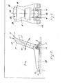
- Figures 1 to 8 show different devices according to the invention, which, however, correspond in many essential components.
- Figure 9 shows an actuation aid.
- the device according to the invention is intended to brake a ski.
- the entire device can be mounted on a ski, for example, before binding.
- the device can have a base plate 2 on which, in the case of the exemplary embodiments according to FIGS. 1, 2 and. 5, 6 a receiving device 22 is arranged. In the exemplary embodiment according to FIGS. 3 and 4, this is the receiving device 21 and in the case of FIGS. 7 and 8 the receiving device 33.
- the receiving device and the base plate can be made in one piece.
- the base plate 2 is at most as wide as a ski 5 and is screwed onto the top of the ski, for example before the binding, for example with the ski 5.
- the ski 5 can already be prepared for such a screw connection or, in general, for fastening the base plate 2.
- the receiving device 21 or 22 or 33 has a bore in which a pivot axis 13 is arranged, which projects beyond the outer sides of the receiving device 21 or 22 or 33.
- An actuating device 8, 9, 10 or 28, designed as a lever has two fork-shaped legs, which are not described in more detail, and which comprise the receiving device 21 or 22 or 33 on the end face. The legs mentioned have bores through which the pivot axis 13 is inserted so that the actuating device 8, 9 or 10 or 28 designed as a lever can pivot about this pivot axis 13. In the starting position, the lever can be about 60 degrees up and forward be directed.
- the fork-shaped legs continue at an angle and form the lever pieces 23, each of these lever pieces 23 being equipped on the underside with an exchangeable brake beam 3.
- the interchangeability is made possible by a screw connection 12.
- Brake bar 3 and lever piece 23 together form the brake piece 7.
- the brake bar 3 is angled slightly at its free end in the direction of the surface 6.
- the lever pieces can also be formed in one piece as a pivotable lever 27 (FIG. 7) and have angled ends 30.
- the receiving device 21 or 22 In its front area in the direction of travel 11, at least the receiving device 21 or 22 has a sharp-edged corner, which serves as a stop 20.
- the inner surface 24, which connects the two lateral legs, comes to bear against this edge forming the stop 20, so that a further pivoting movement is no longer possible.
- the actuating device 8, 9 and 10 and 28 which is designed as a flat lever, has a slightly conical bore which is approximately perpendicular to the pivot axis 13 and is intended as a ski pole guide I.
- This ski pole guide is expanded in the direction of the insertion opening 14 or 15 or 16 or 29 and has an insertion apron 17 or 18 or 19 or 37 in the outermost region. While the apron 17 completely surrounds the ski pole guide 1 designed as a bore and thereby forms an enlarged hollow cone that opens into the ski pole guide 1, the introductory skirts 18, 19 and 37 only partially cover the ski pole guide 1. This makes it possible to easily insert the tip of the ski stick into the ski stick guide 1.
- the device can be actuated by a pivoting movement of the actuating devices 8, 9, 10 or 28 in the direction of arrow 25.
- the tip of the ski pole is inserted into the ski pole guide 1, after which the skier pulls the ski pole towards his body.
- angular positions of the actuating devices 8, 9 or 10 or 28 and angular positions of the brake pieces 7 occur, as are shown in broken lines in the drawings.
- Each brake piece 7 thus penetrates into the subsurface 6 and thereby causes a corresponding braking effect. If the ski pole, not shown, is pushed forward again in the direction of travel 11, the device returns to its starting position. This applies correspondingly to the embodiment according to FIGS. 7 and 8.
- each actuator 8, 9 or 10 or 28 can also, for. B. stand under the preload of a spring.
- at least one spiral spring 4 ' is provided coaxially to the pivot axis 13, which is supported on the one hand on the base plate and on the other hand on the actuating device 8 and 28 designed as a lever.
- the starting position is thick in Figures 1 and 5 and 7. extended location.
- a leaf spring 4a is provided as an elastic element, the leaf spring foot 4 of which is fastened in the region of the base plate 2 and which, for example, rests on the rear side of the actuating device 10.
- This leaf spring 4a is shaped so that it always wants to press the actuating device 10 into the starting position. During the pivoting movement of the actuating device 10 in the direction of arrow 25, the leaf spring 4a must be able to slide on the rear of the actuating device 10. It is therefore only there. In order to avoid damage and injuries, the leaf spring 4a is covered in this area by a cover plate 26, which does not hinder the mobility of the leaf spring.
- FIG. 9 shows an aid to be fastened to the ski pole tip 39 for actuating the braking device according to the invention.
- a split clamping sleeve 40 is clamped over the clamping screws 41.
- the clamping sleeve 40 here has a curved insertion pin 43, the insertion end of which extends parallel to the ski pole tip 39, but at a distance 44 therefrom.
- a cross pin 42 provides the necessary fastening of the insertion pin 43 to the clamping sleeve 40.
- the end of the insertion pin 43 can now be inserted into the openings provided for this purpose in the braking device in order to actuate the braking device.
- the device shown in Figure 9 facilitates insertion and operation. At the same time, the device according to FIG. 9 does not in any way interfere with the handling of the ski pole.
- a simple device that enables reliable braking of the ski.
- two brake pieces are provided for one ski and it it is not absolutely necessary that these brake pieces are arranged on the side of the ski. It is conceivable to provide at least one brake piece in a corresponding opening in the ski. It is also not absolutely necessary for the brake piece and the actuating device to be made in one piece or at least in one unit. An active connection between the two is sufficient.
- a device is also conceivable in which the brake piece can be pivoted in the same way about a pivot axis, but a cam lever or eccentric lever rests on the upper side of the brake piece, which is also held rotatably, whereby the eccentric or cam of this lever then Brake piece 7 is pivoted.
- the eccentric is also in operative connection with the brake piece.
Landscapes
- Braking Arrangements (AREA)
- Golf Clubs (AREA)
- Toys (AREA)
- Footwear And Its Accessory, Manufacturing Method And Apparatuses (AREA)
Priority Applications (1)
| Application Number | Priority Date | Filing Date | Title |
|---|---|---|---|
| AT86116472T ATE60244T1 (de) | 1985-12-12 | 1986-11-27 | Einrichtung zur anordnung an einem ski. |
Applications Claiming Priority (2)
| Application Number | Priority Date | Filing Date | Title |
|---|---|---|---|
| DE19853543829 DE3543829A1 (de) | 1985-12-12 | 1985-12-12 | Einrichtung zur anordnung an einem ski |
| DE3543829 | 1985-12-12 |
Publications (3)
| Publication Number | Publication Date |
|---|---|
| EP0229276A2 true EP0229276A2 (fr) | 1987-07-22 |
| EP0229276A3 EP0229276A3 (en) | 1988-03-09 |
| EP0229276B1 EP0229276B1 (fr) | 1991-01-23 |
Family
ID=6288216
Family Applications (1)
| Application Number | Title | Priority Date | Filing Date |
|---|---|---|---|
| EP86116472A Expired - Lifetime EP0229276B1 (fr) | 1985-12-12 | 1986-11-27 | Dispositif à monter sur un ski |
Country Status (4)
| Country | Link |
|---|---|
| US (1) | US4795183A (fr) |
| EP (1) | EP0229276B1 (fr) |
| AT (1) | ATE60244T1 (fr) |
| DE (2) | DE3543829A1 (fr) |
Families Citing this family (8)
| Publication number | Priority date | Publication date | Assignee | Title |
|---|---|---|---|---|
| US4986561A (en) * | 1987-11-27 | 1991-01-22 | Humphrey Engineering, Inc. | Method and apparatus for speed and maneuverability control for downhill skiing |
| GB8808402D0 (en) * | 1988-04-11 | 1988-05-11 | Boisselle R | Ski-brake |
| US4911461A (en) * | 1989-03-03 | 1990-03-27 | Humphrey Engineering, Inc. | Downhill skis incorporating integral probe assembly for controlling speed and maneuverability |
| US5145200A (en) * | 1990-01-02 | 1992-09-08 | Humphrey Engineering, Inc. | Universal integral ski control system |
| US5356168A (en) * | 1992-12-10 | 1994-10-18 | Ozburn James C | Snow board parking brake apparatus |
| US6866273B2 (en) | 2000-12-08 | 2005-03-15 | The Burton Corporation | Sliding device |
| US8905199B2 (en) | 2012-06-20 | 2014-12-09 | Samuel J. Mann | Control system for downhill skis |
| US12172069B2 (en) * | 2020-12-28 | 2024-12-24 | Stick Rock Solutions LLC | Accessory holder for attaching an accessory to a surface |
Family Cites Families (8)
| Publication number | Priority date | Publication date | Assignee | Title |
|---|---|---|---|---|
| US3724867A (en) * | 1971-05-20 | 1973-04-03 | N Hawthorne | Ski spurs |
| US3899184A (en) * | 1973-05-24 | 1975-08-12 | George S Haddad | Brake for a snow ski |
| US4006911A (en) * | 1975-08-19 | 1977-02-08 | Kraus Robert A | Rigid ski-mounting stabilizer |
| DE2757942A1 (de) * | 1977-12-24 | 1979-06-28 | Rainer Benz | Skibremse fuer langlaufski |
| FR2499418A1 (fr) * | 1981-02-10 | 1982-08-13 | Munoz Jean Luc | Frein pour skis |
| DE3117818A1 (de) * | 1981-05-06 | 1982-12-02 | Helmut 8900 Augsburg Grüner | Steighilfe fuer skier |
| FR2540734A1 (fr) * | 1983-02-15 | 1984-08-17 | Salomon & Fils F | Frein de ski |
| DE3523673A1 (de) * | 1984-12-22 | 1986-07-03 | Matthias 4044 Kaarst Bendt | Langlaufski |
-
1985
- 1985-12-12 DE DE19853543829 patent/DE3543829A1/de not_active Withdrawn
-
1986
- 1986-11-27 AT AT86116472T patent/ATE60244T1/de not_active IP Right Cessation
- 1986-11-27 DE DE8686116472T patent/DE3677173D1/de not_active Expired - Lifetime
- 1986-11-27 EP EP86116472A patent/EP0229276B1/fr not_active Expired - Lifetime
- 1986-12-09 US US06/939,638 patent/US4795183A/en not_active Expired - Fee Related
Also Published As
| Publication number | Publication date |
|---|---|
| EP0229276A3 (en) | 1988-03-09 |
| DE3677173D1 (de) | 1991-02-28 |
| ATE60244T1 (de) | 1991-02-15 |
| EP0229276B1 (fr) | 1991-01-23 |
| US4795183A (en) | 1989-01-03 |
| DE3543829A1 (de) | 1987-06-19 |
Similar Documents
| Publication | Publication Date | Title |
|---|---|---|
| EP0294402B1 (fr) | Systeme de reglage pour fixations de ski | |
| EP0352662B1 (fr) | Surfaces neiges à fixation pour deux chaussures | |
| DE69504518T2 (de) | Bindung für einen schuh auf einem snowboard | |
| EP3195906B1 (fr) | Talonniere ayant une configuration de marche | |
| EP0229276B1 (fr) | Dispositif à monter sur un ski | |
| DE602005005600T2 (de) | Einstellungsvorrichtung für eine Fersenbacke einer Skibindung oder dergleichen | |
| DE3209519A1 (de) | Skibremse | |
| AT526533A4 (de) | Ferseneinheit für eine Tourenskibindung und Tourenskibindung | |
| DE2758658A1 (de) | Skibremse | |
| EP0257244B1 (fr) | Fixation de ski de sécurité, notamment mâchoire avant | |
| DE3132636C2 (de) | "Sicherheitsskibindung zum Tourengehen" | |
| EP2821113B1 (fr) | Butée avant dotée d'un moyen de chaussement | |
| DE1578959B2 (de) | Fersenabstuetzvorrichtung fuer sicherheitsskibindungen | |
| DE29709662U1 (de) | Rollschuh, insbesondere Inline-Skater, mit einer vom Schuh aus betätigbaren Bremseinrichtung | |
| DE2528578A1 (de) | Sicherheitsbindung fuer skischuhe | |
| EP0394380A1 (fr) | Fixation de securite pour ski. | |
| EP2826528A1 (fr) | Unité avant d'une fixation de planche de glisse | |
| EP0443108A2 (fr) | Fixation de sécurité de ski à déclenchement intégrée aux chaussures de ski | |
| EP0408824A2 (fr) | Système de fixation d'une chaussure sur un ski | |
| DE2933671C3 (de) | Sicherheitsskibindung | |
| EP0547531B1 (fr) | Machoire avant | |
| EP0254829B1 (fr) | Fixation de sécurité pour ski | |
| DE69815558T2 (de) | Sicherheitsbindung an der Oberseite des Skistiefels | |
| AT526525B1 (de) | Ferseneinheit einer Skibindung mit einer Skibremse und mit einem Fersenbacken sowie Skibindung, insbesondere Tourenbindung, mit einer derartigen Ferseneinheit | |
| EP4267266B1 (fr) | Dispositif de montage pour fixation de ski |
Legal Events
| Date | Code | Title | Description |
|---|---|---|---|
| PUAI | Public reference made under article 153(3) epc to a published international application that has entered the european phase |
Free format text: ORIGINAL CODE: 0009012 |
|
| AK | Designated contracting states |
Kind code of ref document: A2 Designated state(s): AT BE CH DE FR GB IT LI NL SE |
|
| PUAL | Search report despatched |
Free format text: ORIGINAL CODE: 0009013 |
|
| AK | Designated contracting states |
Kind code of ref document: A3 Designated state(s): AT BE CH DE FR GB IT LI NL SE |
|
| 17P | Request for examination filed |
Effective date: 19880829 |
|
| 17Q | First examination report despatched |
Effective date: 19890208 |
|
| GRAA | (expected) grant |
Free format text: ORIGINAL CODE: 0009210 |
|
| AK | Designated contracting states |
Kind code of ref document: B1 Designated state(s): AT BE CH DE FR GB IT LI NL SE |
|
| PG25 | Lapsed in a contracting state [announced via postgrant information from national office to epo] |
Ref country code: NL Effective date: 19910123 Ref country code: GB Effective date: 19910123 Ref country code: BE Effective date: 19910123 |
|
| REF | Corresponds to: |
Ref document number: 60244 Country of ref document: AT Date of ref document: 19910215 Kind code of ref document: T |
|
| ITF | It: translation for a ep patent filed | ||
| REF | Corresponds to: |
Ref document number: 3677173 Country of ref document: DE Date of ref document: 19910228 |
|
| ET | Fr: translation filed | ||
| NLV1 | Nl: lapsed or annulled due to failure to fulfill the requirements of art. 29p and 29m of the patents act | ||
| GBV | Gb: ep patent (uk) treated as always having been void in accordance with gb section 77(7)/1977 [no translation filed] | ||
| PGFP | Annual fee paid to national office [announced via postgrant information from national office to epo] |
Ref country code: CH Payment date: 19911009 Year of fee payment: 6 |
|
| PGFP | Annual fee paid to national office [announced via postgrant information from national office to epo] |
Ref country code: FR Payment date: 19911025 Year of fee payment: 6 |
|
| PGFP | Annual fee paid to national office [announced via postgrant information from national office to epo] |
Ref country code: SE Payment date: 19911030 Year of fee payment: 6 |
|
| PGFP | Annual fee paid to national office [announced via postgrant information from national office to epo] |
Ref country code: DE Payment date: 19911114 Year of fee payment: 6 |
|
| PLBE | No opposition filed within time limit |
Free format text: ORIGINAL CODE: 0009261 |
|
| STAA | Information on the status of an ep patent application or granted ep patent |
Free format text: STATUS: NO OPPOSITION FILED WITHIN TIME LIMIT |
|
| PGFP | Annual fee paid to national office [announced via postgrant information from national office to epo] |
Ref country code: AT Payment date: 19911129 Year of fee payment: 6 |
|
| 26N | No opposition filed | ||
| PG25 | Lapsed in a contracting state [announced via postgrant information from national office to epo] |
Ref country code: AT Effective date: 19921127 |
|
| PG25 | Lapsed in a contracting state [announced via postgrant information from national office to epo] |
Ref country code: SE Effective date: 19921128 |
|
| PG25 | Lapsed in a contracting state [announced via postgrant information from national office to epo] |
Ref country code: LI Effective date: 19921130 Ref country code: CH Effective date: 19921130 |
|
| PG25 | Lapsed in a contracting state [announced via postgrant information from national office to epo] |
Ref country code: FR Effective date: 19930730 |
|
| REG | Reference to a national code |
Ref country code: CH Ref legal event code: PL |
|
| PG25 | Lapsed in a contracting state [announced via postgrant information from national office to epo] |
Ref country code: DE Effective date: 19930803 |
|
| REG | Reference to a national code |
Ref country code: FR Ref legal event code: ST |
|
| EUG | Se: european patent has lapsed |
Ref document number: 86116472.1 Effective date: 19930610 |
|
| PG25 | Lapsed in a contracting state [announced via postgrant information from national office to epo] |
Ref country code: IT Free format text: LAPSE BECAUSE OF NON-PAYMENT OF DUE FEES;WARNING: LAPSES OF ITALIAN PATENTS WITH EFFECTIVE DATE BEFORE 2007 MAY HAVE OCCURRED AT ANY TIME BEFORE 2007. THE CORRECT EFFECTIVE DATE MAY BE DIFFERENT FROM THE ONE RECORDED. Effective date: 20051127 |