EP0443108A2 - Fixation de sécurité de ski à déclenchement intégrée aux chaussures de ski - Google Patents
Fixation de sécurité de ski à déclenchement intégrée aux chaussures de ski Download PDFInfo
- Publication number
- EP0443108A2 EP0443108A2 EP90122245A EP90122245A EP0443108A2 EP 0443108 A2 EP0443108 A2 EP 0443108A2 EP 90122245 A EP90122245 A EP 90122245A EP 90122245 A EP90122245 A EP 90122245A EP 0443108 A2 EP0443108 A2 EP 0443108A2
- Authority
- EP
- European Patent Office
- Prior art keywords
- hold
- down device
- ski
- pin
- base
- Prior art date
- Legal status (The legal status is an assumption and is not a legal conclusion. Google has not performed a legal analysis and makes no representation as to the accuracy of the status listed.)
- Granted
Links
Images

Classifications
-
- A—HUMAN NECESSITIES
- A63—SPORTS; GAMES; AMUSEMENTS
- A63C—SKATES; SKIS; ROLLER SKATES; DESIGN OR LAYOUT OF COURTS, RINKS OR THE LIKE
- A63C9/00—Ski bindings
- A63C9/08—Ski bindings yieldable or self-releasing in the event of an accident, i.e. safety bindings
- A63C9/084—Ski bindings yieldable or self-releasing in the event of an accident, i.e. safety bindings with heel hold-downs, e.g. swingable
- A63C9/0846—Details of the release or step-in mechanism
-
- A—HUMAN NECESSITIES
- A63—SPORTS; GAMES; AMUSEMENTS
- A63C—SKATES; SKIS; ROLLER SKATES; DESIGN OR LAYOUT OF COURTS, RINKS OR THE LIKE
- A63C9/00—Ski bindings
- A63C9/08—Ski bindings yieldable or self-releasing in the event of an accident, i.e. safety bindings
-
- A—HUMAN NECESSITIES
- A63—SPORTS; GAMES; AMUSEMENTS
- A63C—SKATES; SKIS; ROLLER SKATES; DESIGN OR LAYOUT OF COURTS, RINKS OR THE LIKE
- A63C9/00—Ski bindings
- A63C9/08—Ski bindings yieldable or self-releasing in the event of an accident, i.e. safety bindings
- A63C9/084—Ski bindings yieldable or self-releasing in the event of an accident, i.e. safety bindings with heel hold-downs, e.g. swingable
- A63C9/0841—Ski bindings yieldable or self-releasing in the event of an accident, i.e. safety bindings with heel hold-downs, e.g. swingable with a single jaw
- A63C9/0842—Ski bindings yieldable or self-releasing in the event of an accident, i.e. safety bindings with heel hold-downs, e.g. swingable with a single jaw the jaw pivoting on the body or base about a transverse axis
-
- A—HUMAN NECESSITIES
- A63—SPORTS; GAMES; AMUSEMENTS
- A63C—SKATES; SKIS; ROLLER SKATES; DESIGN OR LAYOUT OF COURTS, RINKS OR THE LIKE
- A63C9/00—Ski bindings
- A63C9/08—Ski bindings yieldable or self-releasing in the event of an accident, i.e. safety bindings
- A63C9/084—Ski bindings yieldable or self-releasing in the event of an accident, i.e. safety bindings with heel hold-downs, e.g. swingable
- A63C9/0845—Ski bindings yieldable or self-releasing in the event of an accident, i.e. safety bindings with heel hold-downs, e.g. swingable the body or base or a jaw pivoting about a vertical axis, i.e. side release
-
- A—HUMAN NECESSITIES
- A63—SPORTS; GAMES; AMUSEMENTS
- A63C—SKATES; SKIS; ROLLER SKATES; DESIGN OR LAYOUT OF COURTS, RINKS OR THE LIKE
- A63C9/00—Ski bindings
- A63C9/08—Ski bindings yieldable or self-releasing in the event of an accident, i.e. safety bindings
- A63C9/0805—Adjustment of the toe or heel holders; Indicators therefor
-
- A—HUMAN NECESSITIES
- A63—SPORTS; GAMES; AMUSEMENTS
- A63C—SKATES; SKIS; ROLLER SKATES; DESIGN OR LAYOUT OF COURTS, RINKS OR THE LIKE
- A63C9/00—Ski bindings
- A63C9/08—Ski bindings yieldable or self-releasing in the event of an accident, i.e. safety bindings
- A63C9/084—Ski bindings yieldable or self-releasing in the event of an accident, i.e. safety bindings with heel hold-downs, e.g. swingable
- A63C9/0847—Details of the manual release
-
- A—HUMAN NECESSITIES
- A63—SPORTS; GAMES; AMUSEMENTS
- A63C—SKATES; SKIS; ROLLER SKATES; DESIGN OR LAYOUT OF COURTS, RINKS OR THE LIKE
- A63C9/00—Ski bindings
- A63C9/08—Ski bindings yieldable or self-releasing in the event of an accident, i.e. safety bindings
- A63C9/085—Ski bindings yieldable or self-releasing in the event of an accident, i.e. safety bindings with sole hold-downs, e.g. swingable
- A63C9/08535—Ski bindings yieldable or self-releasing in the event of an accident, i.e. safety bindings with sole hold-downs, e.g. swingable with a mobile body or base or single jaw
- A63C9/08542—Ski bindings yieldable or self-releasing in the event of an accident, i.e. safety bindings with sole hold-downs, e.g. swingable with a mobile body or base or single jaw pivoting about a transversal axis
Definitions
- the invention relates to a safety ski binding for releasable mounting of a ski boot, with two base parts which can be pivoted together about a ski-fixed pin with a non-circular cross section which is perpendicular to the top of the ski and which can be pushed apart in the longitudinal direction of the shoe against the force of a spring unit which is effective between them and can be pushed apart by the spring unit against opposite sides of the pin curious, which, due to its non-circular cross-section, moves the base parts apart when they pivot from a normal position into an inclined position, and with coupling elements arranged on the base parts, which in the normal position of the base parts are form-fitting and essentially free of play with shoe-resistant counter-coupling elements for ski-fixed mounting of the Ski boots interact and release its counter-coupling elements when the base parts are pushed apart to trigger the ski boot, a hold-down device arranged on a base part as a coupling element, between a locking position and a lockable release position moving in the direction of the ski vertical axis
- the hold-down device arranged on one base part has cams, which interact with associated links on the other base part, in such a way that the two base parts are held in a released position relative to one another by the cams and the link tracks in the released position of the hold-down device.
- a separate locking piston is arranged on a base part, which is pressed by means of a separate spring against a flattened side of the pin facing.
- an actuating force can be generated which tries to bring the base parts into a position in which the longitudinal axis of the base parts runs parallel to the longitudinal axis of the ski and the base part opposite the piston is pressed against the side of the pin facing away from the piston.
- This construction is relatively complex, i.e. a large number of moving parts relative to each other causes greater friction.
- the triggering resistance of the ski binding is influenced not only by the pretension of the spring assembly, but also by the tension of the additional spring acting on the locking piston.
- the object of the invention is now to achieve a simplified construction and improved handling in a ski binding of the type specified at the outset.
- the hold-down device in its release position keeps a base part from the ski-fixed pin, on which the hold-down device is supported directly or indirectly, against the force of the spring unit.
- the hold-down device can interact directly with parts arranged on it or indirectly via transmission parts with the pin, to move the base part carrying the hold-down device off the pin.
- the spring assembly which is clamped between the two base parts and seeks to push them against each other, causes the base part carrying the hold-down element to remain pressed directly onto the pin via the hold-down element or the parts connected or interacting therewith and the other base part. This means that the base parts on the pin remain free of play.
- a torque can optionally be generated, which tries to place the base parts in a desired orientation relative to the ski; all that is required for this is that either the hold-down device or the parts connected or interacting therewith or the other base part are held in pressure by the spring assembly on a non-circular surface of the pin.
- a cam arranged on the hold-down device rests against one end of a plunger, which is guided radially displaceably in the base part carrying the hold-down device and the other end of which is supported on the circumference of the pin.
- the base parts form a plate that vertically supports the ski boot and the shoe-side counter-coupling elements are designed as a shoe-side plate part.
- fixedly arranged vertical projections can be arranged on the base parts, which cooperate with the longitudinal edges of the shoe-side plate part and thus positively fix the shoe in the transverse direction of the shoe.
- the edge of the shoe-side plate part pointing towards the shoe tip can be secured from the front and above by a fixed claw or the like. can be gripped on a base part, while the edge of the plate part facing the heel of the ski boot is encompassed in a corresponding manner by the hold-down device.
- the hold-down device can be depressed from its release position when the ski boot is inserted into the binding through the heel area protruding rearward beyond the shoe-side plate part into the locking position.
- a corresponding arrangement of the hold-down device is also possible on the toe.
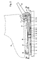
- a bearing plate 2 is fastened on the top of a ski 1, for example by means of screws not shown in the drawing.
- the edges of the bearing plate 2 facing the tip and the rear end of the ski are designed in the form of a circular arc in plan view, both circular arcs having the same curvature and the same center of curvature. Otherwise, the circular-arc-shaped edges of the bearing plate 2 gradually pass into the central region of the bearing plate 2 in the manner shown in FIG. 2, such that the said edges of the bearing plate 2 have a certain vertical distance from the top of the ski 1.
- the bearing plate 2 carries on its top a fixedly arranged in the center of curvature of the circular edges of the bearing plate 2, perpendicular to the ski top 3, which has a pronounced non-circular cross-section and is provided with a plate-like head.
- the pin 3 has between the bearing plate 2 and its plate-like head two facing surfaces, vertical to the top of the ski and parallel to the ski cross axis parallel plane surfaces 4.
- a slideway 5 is arranged, which two symmetrical to the vertical longitudinal plane, relative to each other has obtuse-angled wedge-shaped sections.
- the bearing plate 2 and the pin 3 serve to hold two plate-like base parts 6 and 7. These base parts 6 and 7 are supported with sliding plates 8 on their underside on the upper side of the ski 1.
- the circular arc edges of the bearing plate 2 are arranged recesses which accommodate the circular arc edges of the bearing plate 2 spaced from the top of the ski, such that the base parts 6 and 7 remain displaceable in the longitudinal direction of the ski relative to the bearing plate 2 and with ridges 9 molded onto them are able to reach under the circular arc edges of the bearing plate 2, which are spaced apart from the top of the ski.
- the top of the base parts 6 and 7 is approximately in the same plane as the top of the plate-shaped head of the pin 3. In the vicinity of the pin 3, a recess is formed in the top of the base parts 6 and 7, such that the base parts 6 and 7 den able to reach under the plate-shaped head of the pin 3.
- the plates 10 can be embedded in the material of the base parts 6 and 7.
- the base parts 6 and 7 form a unit which can be pivoted together about the pin 3.
- the transverse distance is less than the diameter of the plate-shaped head of the pin 3.
- the sections of the guide rods 11 protruding to the right from the base part 6 in FIG. 3 pass through bores in the plate 10 of the base part 7 and also adjoining bores 12 arranged in the base part 7, which receive the guide rods 11 without play, but slidably.
- the bores 12 widen in steps in bores 13 which extend to the edge of the base part 7 facing away from the pin 3.
- helical compression springs 14 which are clamped between the step between the bores 12 and 13 on the one hand and on threaded portions of the guide rods 11 screw-adjustable threaded sleeves 15 on the other hand.
- the prestressing of the helical compression springs 14 can be adjusted by a corresponding screw displacement of the threaded sleeves 15 on the guide rods 11.
- the helical compression springs 14 search for the threaded sleeves 15, which are slidably received in the bores 13, to push to the right relative to the base part 7 in FIG. 3. As a result, the base parts 6 and 7 are pressed with their plates 10 against opposite sides of the pin 3.
- a plunger 18 is slidably guided, the end facing the pin 3 cooperates with the slide 5 and the other end protruding into the channel 17 protrudes into a pressure piece 19 which is slidably guided in the channel 17 and one of the non-circular cross-section of the Channel 17 has an adapted cross-section such that the pressure piece 19 is prevented from rotating about the axis of the plunger 18.
- the end face of the pressure piece 19 facing away from the tappet 18 is designed as a flat surface with a notch or step 20 extending in the ski transverse direction.
- a hold-down device 21 is pivotably mounted about an axis 22 parallel to the transverse axis of the base part 7.
- This hold-down device 21 forms, together with an actuating lever 23, a double lever-like part which is provided with a cam 24 which projects downwards.
- This cam 24 protrudes through one slot-like recess on the base part 7 into the channel 17, where the cam 24 rests on the facing end face of the pressure piece 19.
- the cam 24 pushes the pressure piece 19 and thus the plunger 18 relative to the base part 7 to the left, the end of the plunger on the pin side 18 emerges from the assigned opening of the plate 10 of the base part 7 and the base part 7 or its plate 10 forcibly moves away from the facing side of the pin 3.
- the cam 24 engages with the notch or step 20.
- the base part 7 with its plate 10 is moved back towards the pin 3 because the helical compression springs 14 always urge the two base parts 6 and 7 against opposite sides of the pin 3 search.
- the plunger 18 and the pressure piece 19 are displaced relative to the base part 7 in FIG. 2 to the right, the hold-down device 21 being returned to the locking position according to FIG. 2.
- the binding shown serves to accommodate a plate part 26 arranged on the underside of a ski boot 25, which in the normal position of the base parts 6 and 7 shown with the hold-down 21 in the locked position (see FIG. 2) on the top of the base parts 6 and 7 practically free of play is held by positive locking.
- the form fit is effected on the one hand by supporting webs 27 arranged on the longitudinal edges of the base parts 6 and 7, which laterally overlap the longitudinal edges of the shoe-side plate part 26.
- the plate member 26 is prevented from rotating relative to the base members 6 and 7 about an axis perpendicular to the top of the base members 6 and 7.
- the front and rear transverse edges of the plate part 26 are largely immovably held forwards and backwards and upwards by a cross-sectionally claw-shaped stop part 28 at the end of the base part 6 remote from the pin or by the hold-down device 21, as can be seen from FIG. 2.
- the binding shown works as follows: To insert the ski boot 25 or its plate part 26 into the binding, the hold-down device 21 is first brought into its upwardly pivoted release position by depressing its actuating lever 23, which remains set by latching the cam 24 on the notch or step 20 of the pressure piece 19 . In this position of the hold-down 21, the base part 7 is held away from the pin 3 by the plunger 18. The plate 10 of the base part 6 is clamped against the facing flat surface 4 of the pin 3, with the result that the base part 6 and thus also the base part 7 align with their longitudinal axes parallel to the longitudinal axis of the ski 1 or seek to maintain this orientation. The pin-side end of the plunger 18 rests on the rounded wedge tip of the slideway 5.
- the plate member 26 is inserted between the support webs 27 and the stop member 28 and the hold-down 21; this is possible without constraint, because the base part 7 is kept away from the pin 3 and thus also from the base part 6. Then, with the heel region of the ski boot 25 protruding rearward beyond the plate part 26, the hold-down device 21 can be depressed from the release position pivoted in the direction of the arrow P, the cam 24 being lifted out of the locking engagement with the locking notch or step 20 on the pressure piece 19. This unlocking has the result that the compression springs 14 are able to push the base parts 6 and 7 against each other and against opposite sides of the pin 3 until the position shown in FIGS. 1 to 3 is reached.
- the ski boot 25 In the event of a forward fall of the skier, the ski boot 25 tries to stand out from the base part 7 with its heel region (above the hold-down 21). The rear end of the plate part 26 takes the hold-down 21 in the direction of arrow P. With sufficiently large forces, the hold-down device 21 is pivoted so far in the direction of the arrow P, the base part 7 being moved away from the pin 3 and the base part 6 at the same time that the hold-down device 21 can no longer hold the plate part 26. The ski boot 25 is thus released from the binding.
- the ski boot 25 tries to rotate about the axis of the pin 3, the base parts 6 and 7 also being rotated by the interaction of the support webs 27 with the longitudinal edges of the plate part 26.
- the result of this is that the plates 10 of the base parts 6 and 7 which have previously been laid flat on the flat surfaces 4 of the pin 3 assume an inclined position relative to the flat surfaces 4 and can only be supported on diametrically opposed vertical edges of the flat surfaces 4.
- the triggering described last is further facilitated in that the pin-side end of the plunger 18 can increasingly emerge from the associated opening of the plate 10 of the base part 7 when the base parts 6 and 7 are pivoted about the pin 3 due to the shape of the slide 5 on the pin 3 the hold-down device 21 receives a corresponding movement play in the direction of arrow P.
- a hold-down device 21 similar to that of the base part 7 can optionally be arranged on the base part 26 instead of the stop part 28, plunger 18 and pressure piece 19 then being arranged accordingly. This also enables triggering in the case of pure backward falls.
- triggering in the case of pure backward falls can also be made possible in that the stop part 28 engages over the upper side of the shoe-side plate part 26 with an inclined surface rising towards the pin 3. If the tip of the shoe is then lifted off the base part 6 with greater force, a force component occurs in the longitudinal direction of the base part 6 on the said inclined surface, which component increasingly tries to move away from the base part 7.
- cam 24 The ratchet-like interaction of cam 24 and pressure piece 19 can also be achieved by the cam 24 assuming an over-center position in the release position of the hold-down device 21, such that the pressure of the pressure piece 19 acting on the cam 24 causes the hold-down device 21 in the direction of arrow P via the as End position trained release position tries to move.
- the arrangement of the locking notch or step 20 on the pressure piece 19 is unnecessary.
Landscapes
- Footwear And Its Accessory, Manufacturing Method And Apparatuses (AREA)
- Fittings On The Vehicle Exterior For Carrying Loads, And Devices For Holding Or Mounting Articles (AREA)
Applications Claiming Priority (2)
| Application Number | Priority Date | Filing Date | Title |
|---|---|---|---|
| DE4005254A DE4005254C2 (de) | 1990-02-20 | 1990-02-20 | Sicherheitsskibindung zur auslösbaren Halterung eines Skischuhes |
| DE4005254 | 1990-02-20 |
Publications (3)
| Publication Number | Publication Date |
|---|---|
| EP0443108A2 true EP0443108A2 (fr) | 1991-08-28 |
| EP0443108A3 EP0443108A3 (en) | 1991-11-13 |
| EP0443108B1 EP0443108B1 (fr) | 1994-08-03 |
Family
ID=6400538
Family Applications (1)
| Application Number | Title | Priority Date | Filing Date |
|---|---|---|---|
| EP90122245A Expired - Lifetime EP0443108B1 (fr) | 1990-02-20 | 1990-11-22 | Fixation de sécurité de ski à déclenchement intégrée aux chaussures de ski |
Country Status (5)
| Country | Link |
|---|---|
| US (1) | US5116074A (fr) |
| EP (1) | EP0443108B1 (fr) |
| JP (1) | JP3009491B2 (fr) |
| AT (1) | ATE109365T1 (fr) |
| DE (2) | DE4005254C2 (fr) |
Cited By (1)
| Publication number | Priority date | Publication date | Assignee | Title |
|---|---|---|---|---|
| FR2780296A1 (fr) * | 1998-06-26 | 1999-12-31 | Salomon Sa | Dispositif de retenue d'une chaussure sur un engin de glisse |
Families Citing this family (6)
| Publication number | Priority date | Publication date | Assignee | Title |
|---|---|---|---|---|
| US5505477A (en) * | 1993-07-19 | 1996-04-09 | K-2 Corporation | Snowboard binding |
| US5971420A (en) * | 1994-06-06 | 1999-10-26 | Shimano, Inc. | Snowboard binding |
| US6145868A (en) * | 1997-05-16 | 2000-11-14 | The Burton Corporation | Binding system for an article used to glide on snow |
| US5941553A (en) * | 1997-09-15 | 1999-08-24 | Korman; Nathan M. | Boot binding apparatus for a snowboard |
| FR2793155B1 (fr) * | 1999-05-03 | 2001-06-22 | Look Fixations Sa | Fixation declenchable pour la planche de glisse |
| DE102013009762A1 (de) * | 2013-06-10 | 2014-12-11 | Andreas Allmann | Sicherheitsskibindungssystem |
Family Cites Families (9)
| Publication number | Priority date | Publication date | Assignee | Title |
|---|---|---|---|---|
| FR1587912A (fr) * | 1968-09-06 | 1970-04-03 | ||
| AT311229B (de) * | 1971-03-12 | 1973-11-12 | Smolka & Co Wiener Metall | Skibindung |
| AT325485B (de) * | 1973-06-07 | 1975-10-27 | Smolka & Co Wiener Metall | Auslöseskibindung |
| US4182524A (en) * | 1977-08-26 | 1980-01-08 | Look S.A. | Safety ski binding |
| FR2400923A1 (fr) * | 1977-08-26 | 1979-03-23 | Beyl Jean Joseph Alfred | Fixation de securite pour ski |
| DE2749904A1 (de) * | 1977-11-08 | 1979-05-10 | Gerhard Dr Welzel | Schisicherheitsbindung |
| FR2410447A1 (fr) * | 1977-12-02 | 1979-06-29 | Beyl Jean Joseph Alfred | Chaussure de ski |
| CH627945A5 (en) * | 1978-06-27 | 1982-02-15 | Suhner Intertrade Ag | Ski binding having a support which can be rotated about a vertical axis |
| FR2430777A1 (fr) * | 1978-07-13 | 1980-02-08 | Look Sa | Ensemble chaussure et fixation de ski |
-
1990
- 1990-02-20 DE DE4005254A patent/DE4005254C2/de not_active Expired - Fee Related
- 1990-11-22 AT AT90122245T patent/ATE109365T1/de not_active IP Right Cessation
- 1990-11-22 DE DE59006703T patent/DE59006703D1/de not_active Expired - Fee Related
- 1990-11-22 EP EP90122245A patent/EP0443108B1/fr not_active Expired - Lifetime
-
1991
- 1991-02-12 US US07/653,967 patent/US5116074A/en not_active Expired - Fee Related
- 1991-02-18 JP JP3023431A patent/JP3009491B2/ja not_active Expired - Lifetime
Cited By (1)
| Publication number | Priority date | Publication date | Assignee | Title |
|---|---|---|---|---|
| FR2780296A1 (fr) * | 1998-06-26 | 1999-12-31 | Salomon Sa | Dispositif de retenue d'une chaussure sur un engin de glisse |
Also Published As
| Publication number | Publication date |
|---|---|
| JPH04218183A (ja) | 1992-08-07 |
| US5116074A (en) | 1992-05-26 |
| DE4005254A1 (de) | 1991-08-22 |
| EP0443108B1 (fr) | 1994-08-03 |
| ATE109365T1 (de) | 1994-08-15 |
| DE4005254C2 (de) | 2001-06-21 |
| JP3009491B2 (ja) | 2000-02-14 |
| EP0443108A3 (en) | 1991-11-13 |
| DE59006703D1 (de) | 1994-09-08 |
Similar Documents
| Publication | Publication Date | Title |
|---|---|---|
| EP2608853B1 (fr) | Butée arrière de randonnee avec plage de glissement dynamique | |
| DE1960002C3 (de) | Auslösende Skibindung mit einer verschwenkbaren Trittplatte | |
| EP3702005B1 (fr) | Talonnière | |
| DE102012201812B4 (de) | Vordereinheit für eine Gleitbrettbindung, Tourenbindung und Skisprungbindung | |
| EP0351881A2 (fr) | Fixation recouplée au réglage d'une tige de chaussure de ski | |
| EP0295372A1 (fr) | Butée avant pour fixation de sécurité pour ski déclenchable latéralement | |
| EP3345659B1 (fr) | Talonnière automatique pour une fixation de ski | |
| DE2927059A1 (de) | Skischuh mit integrierter skibindung | |
| EP0394513B1 (fr) | Fixation de sécurité de ski | |
| DE2757723C2 (fr) | ||
| EP1559455B1 (fr) | Fixation adaptée au ski de randonnée | |
| EP0443108B1 (fr) | Fixation de sécurité de ski à déclenchement intégrée aux chaussures de ski | |
| DE2758658A1 (de) | Skibremse | |
| DE2528578A1 (de) | Sicherheitsbindung fuer skischuhe | |
| DE69602509T2 (de) | Schuhrückhaltevorrichtung auf einem Snowboard bzw. Ski oder ähnlichem | |
| DE3035738A1 (de) | Skibremse | |
| DE3151222A1 (de) | Vorderbacken fuer eine sicherheits-skibindung | |
| EP0408824A2 (fr) | Système de fixation d'une chaussure sur un ski | |
| DE2159638C3 (de) | Vorderbacken für Sicherheitsskibindungen | |
| EP0354482A2 (fr) | Fixation de sécurité de ski | |
| DE3725482A1 (de) | Antireibungsplatte mit automatischer zentrierung fuer monoblock-sicherheitsbindung | |
| EP0438659B1 (fr) | Fixation déclenchable | |
| DE4121777C2 (de) | Skibremse | |
| EP3858447A1 (fr) | Mâchoire de retenue du talon pour une fixation de descente ou fixation combinée de descente et de tour | |
| DE2661062C2 (de) | Langlaufbindung |
Legal Events
| Date | Code | Title | Description |
|---|---|---|---|
| PUAI | Public reference made under article 153(3) epc to a published international application that has entered the european phase |
Free format text: ORIGINAL CODE: 0009012 |
|
| AK | Designated contracting states |
Kind code of ref document: A2 Designated state(s): AT CH DE FR IT LI |
|
| PUAL | Search report despatched |
Free format text: ORIGINAL CODE: 0009013 |
|
| AK | Designated contracting states |
Kind code of ref document: A3 Designated state(s): AT CH DE FR IT LI |
|
| 17P | Request for examination filed |
Effective date: 19911216 |
|
| 17Q | First examination report despatched |
Effective date: 19930318 |
|
| ITF | It: translation for a ep patent filed | ||
| GRAA | (expected) grant |
Free format text: ORIGINAL CODE: 0009210 |
|
| AK | Designated contracting states |
Kind code of ref document: B1 Designated state(s): AT CH DE FR IT LI |
|
| REF | Corresponds to: |
Ref document number: 109365 Country of ref document: AT Date of ref document: 19940815 Kind code of ref document: T |
|
| REF | Corresponds to: |
Ref document number: 59006703 Country of ref document: DE Date of ref document: 19940908 |
|
| ET | Fr: translation filed | ||
| PLBE | No opposition filed within time limit |
Free format text: ORIGINAL CODE: 0009261 |
|
| STAA | Information on the status of an ep patent application or granted ep patent |
Free format text: STATUS: NO OPPOSITION FILED WITHIN TIME LIMIT |
|
| REG | Reference to a national code |
Ref country code: FR Ref legal event code: TP |
|
| 26N | No opposition filed | ||
| PGFP | Annual fee paid to national office [announced via postgrant information from national office to epo] |
Ref country code: CH Payment date: 19951129 Year of fee payment: 6 |
|
| PG25 | Lapsed in a contracting state [announced via postgrant information from national office to epo] |
Ref country code: LI Effective date: 19961130 Ref country code: CH Effective date: 19961130 |
|
| REG | Reference to a national code |
Ref country code: CH Ref legal event code: PL |
|
| PGFP | Annual fee paid to national office [announced via postgrant information from national office to epo] |
Ref country code: FR Payment date: 20041118 Year of fee payment: 15 |
|
| PGFP | Annual fee paid to national office [announced via postgrant information from national office to epo] |
Ref country code: AT Payment date: 20041122 Year of fee payment: 15 |
|
| PGFP | Annual fee paid to national office [announced via postgrant information from national office to epo] |
Ref country code: DE Payment date: 20050128 Year of fee payment: 15 |
|
| PG25 | Lapsed in a contracting state [announced via postgrant information from national office to epo] |
Ref country code: IT Free format text: LAPSE BECAUSE OF NON-PAYMENT OF DUE FEES;WARNING: LAPSES OF ITALIAN PATENTS WITH EFFECTIVE DATE BEFORE 2007 MAY HAVE OCCURRED AT ANY TIME BEFORE 2007. THE CORRECT EFFECTIVE DATE MAY BE DIFFERENT FROM THE ONE RECORDED. Effective date: 20051122 Ref country code: AT Free format text: LAPSE BECAUSE OF NON-PAYMENT OF DUE FEES Effective date: 20051122 |
|
| PG25 | Lapsed in a contracting state [announced via postgrant information from national office to epo] |
Ref country code: DE Free format text: LAPSE BECAUSE OF NON-PAYMENT OF DUE FEES Effective date: 20060601 |
|
| PG25 | Lapsed in a contracting state [announced via postgrant information from national office to epo] |
Ref country code: FR Free format text: LAPSE BECAUSE OF NON-PAYMENT OF DUE FEES Effective date: 20060731 |
|
| REG | Reference to a national code |
Ref country code: FR Ref legal event code: ST Effective date: 20060731 |