EP0229414A2 - Vorrichtung zur Reinigung von Wasser, insbesondere Salzwasser, durch Umkehrosmose - Google Patents
Vorrichtung zur Reinigung von Wasser, insbesondere Salzwasser, durch Umkehrosmose Download PDFInfo
- Publication number
- EP0229414A2 EP0229414A2 EP86202187A EP86202187A EP0229414A2 EP 0229414 A2 EP0229414 A2 EP 0229414A2 EP 86202187 A EP86202187 A EP 86202187A EP 86202187 A EP86202187 A EP 86202187A EP 0229414 A2 EP0229414 A2 EP 0229414A2
- Authority
- EP
- European Patent Office
- Prior art keywords
- chamber
- piston
- pinion
- screw
- water
- Prior art date
- Legal status (The legal status is an assumption and is not a legal conclusion. Google has not performed a legal analysis and makes no representation as to the accuracy of the status listed.)
- Granted
Links
Images


Classifications
-
- B—PERFORMING OPERATIONS; TRANSPORTING
- B01—PHYSICAL OR CHEMICAL PROCESSES OR APPARATUS IN GENERAL
- B01D—SEPARATION
- B01D61/00—Processes of separation using semi-permeable membranes, e.g. dialysis, osmosis or ultrafiltration; Apparatus, accessories or auxiliary operations specially adapted therefor
- B01D61/02—Reverse osmosis; Hyperfiltration ; Nanofiltration
- B01D61/08—Apparatus therefor
-
- B—PERFORMING OPERATIONS; TRANSPORTING
- B01—PHYSICAL OR CHEMICAL PROCESSES OR APPARATUS IN GENERAL
- B01D—SEPARATION
- B01D63/00—Apparatus in general for separation processes using semi-permeable membranes
- B01D63/06—Tubular membrane modules
- B01D63/068—Tubular membrane modules with flexible membrane tubes
-
- B—PERFORMING OPERATIONS; TRANSPORTING
- B01—PHYSICAL OR CHEMICAL PROCESSES OR APPARATUS IN GENERAL
- B01D—SEPARATION
- B01D2313/00—Details relating to membrane modules or apparatus
- B01D2313/24—Specific pressurizing or depressurizing means
-
- C—CHEMISTRY; METALLURGY
- C02—TREATMENT OF WATER, WASTE WATER, SEWAGE, OR SLUDGE
- C02F—TREATMENT OF WATER, WASTE WATER, SEWAGE, OR SLUDGE
- C02F2103/00—Nature of the water, waste water, sewage or sludge to be treated
- C02F2103/08—Seawater, e.g. for desalination
-
- Y—GENERAL TAGGING OF NEW TECHNOLOGICAL DEVELOPMENTS; GENERAL TAGGING OF CROSS-SECTIONAL TECHNOLOGIES SPANNING OVER SEVERAL SECTIONS OF THE IPC; TECHNICAL SUBJECTS COVERED BY FORMER USPC CROSS-REFERENCE ART COLLECTIONS [XRACs] AND DIGESTS
- Y02—TECHNOLOGIES OR APPLICATIONS FOR MITIGATION OR ADAPTATION AGAINST CLIMATE CHANGE
- Y02A—TECHNOLOGIES FOR ADAPTATION TO CLIMATE CHANGE
- Y02A20/00—Water conservation; Efficient water supply; Efficient water use
- Y02A20/124—Water desalination
- Y02A20/131—Reverse-osmosis
Definitions
- the invention relates to a device for purifying salt water in particular, which will hereinafter be referred to as "primary water", with a view to producing potable fresh water. It relates to a device of the type in which the purification is produced, by reverse osmosis, dose by dose, during discontinuous operating sequences.
- the osmotic pressure is around 25 bars, while for brackish water with a salinity of 10 g / l, the osmotic pressure is around 7 bars: pressures on the order of 3 to 4 times these values are generally necessary to ensure a satisfactory filtration rate.
- the present invention relates to a purification device by reverse osmosis of the type comprising mechanical means for producing the necessary pressure, in order to be usable both in land missions for purifying brackish water, and in marine environment for desalinating water. sea.
- the object of the invention is to provide a device of simple structure, the size and cost of which are compatible with transport and individual use.
- Another objective is to allow drinking fresh water to be obtained with a very moderate effort, capable of being produced by any individual even in a state of great fatigue.
- the applicant has freed itself from the path traced for 10 years by recent research and has turned to a device operating in discontinuous sequences, making it possible to produce at each sequence a dose of fresh water.
- the inventive step therefore consisted in choosing an operating principle that was abandoned and a priori condemned by specialists, and in finding an extremely simple solution to guarantee the effectiveness of the device operating on this principle, which fully satisfied the requirements of the application. .
- the device for purifying primary water, in particular salt water, targeted by the invention comprises: a primary water chamber extending along an axis and adapted to withstand a high pressure greater than the osmotic pressure of said primary water, means for filling said chamber with primary water, prior to each sequence, - means of collecting drinking water at low pressure, - At least one semi-permeable membrane capable of performing reverse osmosis filtration of primary water contained in the chamber, said membrane being housed in said chamber so that one of its active faces, called the upstream active face, is immersed in the primary water thereof and that its other active face, called the downstream active face, communicates with the means for collecting drinking water, - A movable piston arranged to be able to penetrate axially into the chamber between a withdrawal position and a maximum penetration position and adapted so that the volume (V2) swept by said piston during its movement is small compared to the total available capacity (V1) from the bedroom,
- this device is characterized in that: . the chamber internally contains a coaxial sleeve in which the piston is able to move in sealed manner, . the semi-permeable membrane is positioned in a peripheral annular portion of said chamber so as to release the central portion thereof for the coaxial sleeve, .
- a rotary drive said input member is externally articulated by an axis in the vicinity of one end of the chamber so as to be able to rotate in a plane parallel to the axis of the latter, .
- a first pinion of conical type is carried by the articulation axis of the input member, so as to be integral in rotation with the latter, .
- a second pinion of greater diameter is disposed coaxially with the chamber, outside of the latter in the immediate vicinity of its end, this second pinion being provided with a bevel gear meshed with the first and having an axial hole tapped, . centering and abutment means are associated with the second pinion to keep it in an axial position engaged with the first pinion, .
- a screw extends along the axis of the chamber and of the sleeve to engage in the tapped hole of the second pinion, said screw carrying the piston, . means for setting in rotation are associated with the screw in order to prevent its rotation.
- Total available capacity V1 means the difference between the total volume of the chamber when the piston is in the retracted position, and the volume occupied by the semi-permeable membrane (and if necessary by any other accessory placed in the chamber): this capacity V1 therefore represents the volume of primary water which can be introduced initially into the chamber.
- the chamber and the piston are arranged so that the ratio the total available capacity of the chamber at the volume swept by the piston is greater than 3, in particular between 4 and 12, for example of the order of 6 to 8.
- a user developing a very moderate power on the input member is able to produce, by means of these mechanical means and of the piston, the necessary pressures on the primary water.
- the piston and the mechanical drive means are adapted without difficulty to produce a pressure of between 20 and 30 bars from a power less than 20 watts.
- These means are also suitable for the purification of sea water and are then adapted to produce a pressure between 50 and 80 bars from a power lower than the same threshold.
- the drive of the axis of the input member can, if necessary, be provided by a motor, in particular by an electric motor).
- the primary water chamber is provided telescopic and consists of two cylindrical enclosures arranged to slide sealingly one inside the other between a retracted position and a deployed position.
- This means combines with all of the means already described to allow, at the same time, to have a primary water chamber of large volume relative to the dose of drinking water desired in each sequence, while benefiting from '' a compact device in the inactive state.
- the two enclosures are retracted one inside the other. Before each use, the operator deploys these enclosures to give the primary water chamber the capacity V1 necessary during operation.
- the chamber has a generally cylindrical shape and the piston has a smaller section than that of said chamber. If D2 represents the diameter of the piston and H2 the chamber height swept by it, the chamber is advantageously dimensioned so that: 1.6 H2 ⁇ H1 ⁇ 2.4 H2 and 1.6 D2 ⁇ D1 ⁇ 2.4 D2 where H1 and D1 respectively represent the total height of the chamber and its average diameter.
- the semi-permeable reverse osmosis membrane can be of any known type.
- this membrane can be a tubular membrane of a type known per se (made of cellulose acetate, aromatic polyamide or the like), wound in turns in the primary water chamber; the active upstream face of this membrane is constituted by the external face of the tube which forms it, and bathes in the primary water contained in said chamber, while the active downstream face is constituted by the internal face of the membrane and is in communication with the means of collecting drinking water to ensure the flow of filtered drinking water towards them.
- These collection means comprise in particular, on the one hand, an external connection connector extending by a channel which passes through the wall of the chamber, on the other hand, at least one tubular endpiece disposed in this channel on the internal side; this nozzle is adapted to maintain one end of the tubular membrane so that its active downstream face (internal face) communicates with the external connector.
- the other end of the semi-permeable membrane can be closed so that the flow of drinking water is effected through only one end; this other end can also be fixed to another end piece, in the same way as the first, to allow a flow of filtered water through the two ends.
- means for returning the piston are advantageously provided to allow, between two sequences, to generate its rapid displacement between the position of maximum penetration and the position of withdrawal.
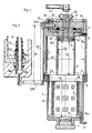
- the device shown by way of example in FIGS. 1, 2, 3 and 4 has a total bulk in the retracted state which can be approximately 1.5 liters (it is represented in these figures on a scale equal to approximately 0.7). It is particularly intended to supplement individual equipment carried during land missions, in order to provide the person concerned with potable fresh water from polluted and / or brackish water (salinity level: 10 g / l ), for example from marshes, wells, ponds ...
- This device comprises two cylindrical enclosures 1 and 2 which are mounted telescopically with respect to each other and adapted to withstand a pressure of the order of a hundred bars. These enclosures face each other by an open face and are arranged with collinear axes, so that the second enclosure 2 can slide sealingly in the first enclosure 1 between a retracted position (FIG. 4) and a deployed position (FIGS. 1 and 3) .
- the two enclosures delimit a chamber called the primary water chamber 3.
- the depth of the two enclosures is roughly identical so as to allow complete retraction of enclosure 2 into enclosure 1.
- the second enclosure 2 is provided on a peripheral excess thickness 2a with an O-ring seal 4 which cooperates with the internal wall of the first enclosure.
- the latter is provided with a ring 5 screwed at its end in order to produce an end-of-travel stop in the deployed position.
- the first enclosure 1 is extended at its other end by an annular border 1a and is internally provided with a coaxial sleeve 6 which extends over its height.
- the bore of this sleeve has a diameter D2 which can be of the order of half of the average diameter D1 of the chamber 3.
- This sleeve 6 opens at its two ends, on one side towards the enclosure 2, and on the other outside enclosure 1.
- the bottom of the second enclosure 2 is pierced with a large filling orifice which is closed by a removable plug 7 screwed into it.
- this orifice carries a prefiltration capsule symbolized at 8, capable of stopping any large particles suspended in the primary water introduced.
- the enclosure 2 contains an openwork cylindrical coil 9 which extends along the latter around the axial volume located directly above the sleeve 6 above and has two end flanges. During the retraction of the two enclosures, the sleeve 6 is therefore housed inside this coil 9.
- the latter carries a tubular cord 10 which is wrapped around the latter and is constituted by a semi-permeable tubular membrane reverse osmosis of known type, for example cellulose acetate.
- One end 10a of said membrane is associated with means for collecting the fresh water obtained inside it.
- the end 10a of the tubular membrane enters a rigid tubular end-piece 11 whose bore corresponds to the external diameter of said membrane.
- This nozzle which has an internal shoulder for stopping the membrane is fitted and glued in a hole 9a which is pierced with the corresponding flange of the coil 9; the end of this endpiece, opposite the membrane, enters a channel 2b of which the bottom of the enclosure 2 is pierced.
- This channel comprises a section of enlarged diameter in which is housed an O-ring seal 11a ensuring the sealing around the end piece 11, between the latter and the bottom of the enclosure 2.
- the channel 2b is extended in an external connection fitting 12 which can be provided with a flexible conduit or flow directly into a container.
- a latex sleeve 13 is engaged on the internal projecting part of the end piece 11 and on the tubular membrane 10 in order to ensure sealing. It should be noted that this assembly guarantees an excellent seal which increases with the pressure prevailing in the primary water chamber 3.
- the other end of the semi-permeable membrane 10 can be closed; it is also possible to connect this other end to another nozzle arranged like the first in order to ensure a flow in the membrane in both directions.
- the two end pieces then open into the same external connection.
- the assembly, coil, membrane, tip can constitute an interchangeable whole in order to allow easy replacement of the membranes. It should be noted that a snap on of the coil can be provided to keep the assembly in place.
- the first enclosure is provided with a calibrated valve 14 which opens towards the outside if the pressure in the chamber 3 exceeds a predetermined calibration threshold.
- the sleeve 6 of the first enclosure contains a cylindrical piston 15 which can move inside this sleeve between a withdrawal position ( Figure 1) and a position of maximum penetration ( Figure 3).
- This piston carries on its periphery an O-ring 16 which cooperates with the bore of the sleeve.
- the piston 15 is associated with mechanical drive means with manual actuation, which make it possible to move it between its two positions. During this translation, the piston scans the internal volume V2 of the muff. This volume is small compared to the total volume of the primary chamber. The dose of drinking water produced in each sequence is equal to this volume V2.
- the height H2 swept by the piston can be of the order of half the total height H1 of the primary water chamber, while the diameter D2 of said piston can itself be of the order of half the average diameter D1 of said chamber.
- the ratio of the total volume of the chamber to the volume swept by the piston is very approximately of the order of 8.
- the semi-permeable membrane and the coil which carries it occupy a small volume compared to the total volume of the chamber (of around 15% to 20%) so that the ratio between the total available capacity of the chamber V1 and the swept volume V2 is in the example much greater than 3 and of the order of 7.
- the dose of drinking water produced corresponds to 1/7 of the quantity of primary water introduced.
- the piston 15 is carried by a screw 17 which extends along the axis of the enclosures 1, 2 and of the sleeve 6.
- This screw passes through an axial threaded hole of a pinion 18 disposed coaxially with the enclosure 1 to 1 inside its annular border 1a.
- This pinion 18 has a bevel gear 18a on its periphery and a central collar 18b which is housed in the orifice of the sleeve 6 to ensure axial centering of said pinion.
- This pinion 18 is held opposite the enclosure 1 by a ball stop 19 fitted into a retaining part 20.
- This part 20 is axially pierced to preserve the free passage of the screw 17. It is retained in the border annular 1a of the enclosure by a clip 21.
- the part 20 forms a housing in which is hinged a bevel gear 22 of diameter smaller than the previous one.
- This pinion 22, in engagement with the pinion 18, is carried by a hinge pin 23a, integral with an inlet crank 23 and orthogonal to the axis of the enclosure 1.
- This crank is articulated on the annular edge 1a of enclosure 1, so that it can rotate near this enclosure in a plane parallel to the axis of said enclosure.
- the pinion 22 is keyed on the hinge pin 23a.
- the crank 23 of length M carries at its free end an operating rod 23b which can be screwed or hinged thereon.
- the dimensioning of these mechanical means is advantageously provided so that the force multiplication ratio between crank and screw is between 500 and 1,500, and that the reduction in movement is such that a crank turn generates a displacement of the screw between 0.5 and 2 mm. This allows with very modest powers (in all cases less than 20 watts) to produce the necessary pressures at the level of the piston 15.
- the screw 17 is equipped at its free end with a short crank 24 which fulfills two functions: on the one hand, it serves as a gripping means making it possible to wedge the said screw and to prevent it from turning during the sequences filtration, on the other hand, it serves as means for rapid return of the piston after each sequence.
- a bellows 25 is preferably provided externally around the screw 17 to protect the latter when it is outside the enclosure 1.
- FIGS 5a to 5f illustrate the operation of such an apparatus.
- Figure 5a shows the device in the retracted state for its transport and storage.
- the use of composite materials in the manufacture of the latter allows it to be given an empty weight of less than 2 kgs.
- FIG. 5b illustrates the deployment of the enclosures 1 and 2, the plug 7 having been removed.
- FIG. 5c illustrates the rapid return phase of the screw 17 from the maximum penetration position towards the withdrawal position, by actuating the short crank 24 and retaining the crank 23.
- Figure 5d illustrates the filling of the primary water chamber.
- FIG. 5c illustrates a filtration sequence the duration of which is of the order of 100 seconds.
- the operator actuates the crank 23 and retains the crank 24.
- the valve 14 lets out the primary water and the operator must slow down its movement.
- FIG. 5f illustrates the emptying of the chamber between two filtration sequences.
- FIG. 6 represents another exemplary embodiment where the primary water chamber is delimited by a single enclosure.
- This device has an elongated shape which makes it easy to include it in survival for pleasure craft, in order to desalinate sea water (salinity rate: 35 g / l).
Landscapes
- Chemical & Material Sciences (AREA)
- Engineering & Computer Science (AREA)
- Water Supply & Treatment (AREA)
- Chemical Kinetics & Catalysis (AREA)
- Nanotechnology (AREA)
- Separation Using Semi-Permeable Membranes (AREA)
Applications Claiming Priority (2)
| Application Number | Priority Date | Filing Date | Title |
|---|---|---|---|
| FR8518460A FR2591214B1 (fr) | 1985-12-11 | 1985-12-11 | Dispositif d'epuration d'eau notamment salee, par osmose inverse |
| FR8518460 | 1985-12-11 |
Publications (3)
| Publication Number | Publication Date |
|---|---|
| EP0229414A2 true EP0229414A2 (de) | 1987-07-22 |
| EP0229414A3 EP0229414A3 (en) | 1987-08-05 |
| EP0229414B1 EP0229414B1 (de) | 1990-04-18 |
Family
ID=9325742
Family Applications (1)
| Application Number | Title | Priority Date | Filing Date |
|---|---|---|---|
| EP86202187A Expired - Lifetime EP0229414B1 (de) | 1985-12-11 | 1986-12-01 | Vorrichtung zur Reinigung von Wasser, insbesondere Salzwasser, durch Umkehrosmose |
Country Status (5)
| Country | Link |
|---|---|
| US (1) | US4740301A (de) |
| EP (1) | EP0229414B1 (de) |
| DE (1) | DE3670451D1 (de) |
| ES (1) | ES2014232B3 (de) |
| FR (1) | FR2591214B1 (de) |
Families Citing this family (9)
| Publication number | Priority date | Publication date | Assignee | Title |
|---|---|---|---|---|
| DE60234860D1 (de) | 2001-07-16 | 2010-02-04 | Miox Corp | Durch doppelkopfpumpe angetriebenes membransystem |
| RU2008116677A (ru) * | 2005-09-28 | 2009-11-10 | Конинклейке Филипс Электроникс Н.В. (Nl) | Управляемое вручную устройство для очистки воды |
| US8313644B2 (en) * | 2010-01-13 | 2012-11-20 | OZOlab | Bottle with an integrated filtration assembly that is manually operated using a plunger |
| DE102011007003C5 (de) * | 2011-04-07 | 2016-09-08 | Georg Schünemann GmbH | Bernoulli-Filter und Verfahren zum Filtrieren von Flüssigkeiten |
| US10106441B2 (en) * | 2016-09-07 | 2018-10-23 | University Of Dammam | Submersible desalination apparatus |
| US11638891B2 (en) * | 2017-05-23 | 2023-05-02 | Kohler Co. | Water filter system |
| IL258698A (en) * | 2018-04-15 | 2018-05-31 | Amiad Water Systems Ltd | A control mechanism for self-cleaning filter systems |
| US12128334B2 (en) * | 2018-09-05 | 2024-10-29 | Kin Mun Chin | Filter press with threadably advanced filtrate receiving plunger |
| MY195849A (en) * | 2018-09-05 | 2023-02-23 | Kin Mun Chin | Device for Filtering |
Family Cites Families (6)
| Publication number | Priority date | Publication date | Assignee | Title |
|---|---|---|---|---|
| DE14211C (de) * | G. H. HEDRICH in Pegau (Sachsen) | Neuerungen an Ziegel- und Thonwaaren-Pressen | ||
| DE252001C (de) * | ||||
| FR683096A (fr) * | 1929-10-04 | 1930-06-05 | Irlandes Et Pons Ets | Presse universelle |
| DE1517523A1 (de) * | 1966-12-09 | 1970-04-02 | Babcock & Wilcox Ag | Trinkwasserfilter |
| US4070280A (en) * | 1976-11-17 | 1978-01-24 | Desalination Systems, Inc. | Manually operable reverse osmosis apparatus |
| FR2503129A1 (fr) * | 1981-04-06 | 1982-10-08 | Lopez Fernand | Dispositif de production d'eau douce a partir d'eau de mer par osmose inverse |
-
1985
- 1985-12-11 FR FR8518460A patent/FR2591214B1/fr not_active Expired
-
1986
- 1986-12-01 EP EP86202187A patent/EP0229414B1/de not_active Expired - Lifetime
- 1986-12-01 ES ES86202187T patent/ES2014232B3/es not_active Expired - Lifetime
- 1986-12-01 DE DE8686202187T patent/DE3670451D1/de not_active Expired - Lifetime
- 1986-12-11 US US06/940,736 patent/US4740301A/en not_active Expired - Lifetime
Also Published As
| Publication number | Publication date |
|---|---|
| EP0229414B1 (de) | 1990-04-18 |
| ES2014232B3 (es) | 1990-07-01 |
| FR2591214B1 (fr) | 1989-10-20 |
| US4740301A (en) | 1988-04-26 |
| EP0229414A3 (en) | 1987-08-05 |
| DE3670451D1 (de) | 1990-05-23 |
| FR2591214A1 (fr) | 1987-06-12 |
Similar Documents
| Publication | Publication Date | Title |
|---|---|---|
| EP0062944B1 (de) | Vorrichtung zur Erzeugung von Süsswasser aus Meereswasser mittels Umkehrosmose | |
| EP0242377A1 (de) | Vorrichtung zur meereswasserentsalzung mittels umkehrosmose. | |
| EP0499509B1 (de) | Verfahren und verbesserte Vorrichtung zum Filtrieren mit tangentiellem, instationärem Flüssigkeitsstrom | |
| EP0229414B1 (de) | Vorrichtung zur Reinigung von Wasser, insbesondere Salzwasser, durch Umkehrosmose | |
| EP2897716B1 (de) | Unterwasser-wasserbehandlungseinheit und verfahren zur reinigung dieser einheit | |
| EP0251840B1 (de) | Verfahren und persönlicher Apparat für die Filtrierung einer Flüssigkeit | |
| EP2897714B1 (de) | Verfahren zur unterwasserüberprüfung eines filtrations-systems | |
| WO1988010239A1 (fr) | Procede et appareil de production d'eau potable | |
| EP1372809B1 (de) | Vorrichtung zum kontinuierlichen filtrieren von flüssigkeiten mittels ultraschall mit hoher leistungsdichte | |
| FR2484391A1 (fr) | Procede et dispositif de production d'eau douce a partir d'eau de mer | |
| EP2021108B1 (de) | Verfahren zur reinigung der membran einer vorrichtung zur querstromfilteration von wein | |
| FR2518892A1 (fr) | Detecteur de pollution de carburant avec valve de retenue | |
| FR2513536A1 (fr) | Dispositif de filtration d'un liquide | |
| FR2732727A1 (fr) | Dispositif autonome non motorise de traitement de liquide par circulation dans une chambre haute pression et dispositif amplificateur de pression de liquide non motorise | |
| FR2580188A1 (fr) | Procede et dispositif pour filtrer une suspension de particules dans un liquide | |
| FR2918364A1 (fr) | Dispositif autonome d'epuration d'eau de mer a modules de filtration immerges alteratifs a chambres basse pression multipistons | |
| FR2918363A1 (fr) | Dispositif autonome d'epuration d'eau de mer a modules de filtration immerges alternatifs a chambres basse pression reliees entre elles | |
| FR2804881A1 (fr) | Dispositif d'epuration de liquides | |
| FR2927099A1 (fr) | Dispositif d'alimentation sequentiel notamment d'un bac de filtration | |
| WO2012140070A1 (fr) | Kit d'extraction par evaporation osmotique et procede le mettant en oeuvre | |
| FR2520420A1 (fr) | Appareil de nettoyage automatique d'une surface immergee, en particulier de parois de piscine | |
| FR2553297A1 (fr) | Filtre a liquide permettant notamment de retirer en continu des particules contenues dans de l'eau apres decoupe de dispositifs a semi-conducteurs | |
| FR3151322A1 (fr) | Système de filtration d’eau non potable | |
| WO2025119953A1 (fr) | Système mobile d'aspiration de végétaux en suspension dans un liquide | |
| FR3054580A1 (fr) | Module de filtration pour piscine et piscine le comportant |
Legal Events
| Date | Code | Title | Description |
|---|---|---|---|
| PUAI | Public reference made under article 153(3) epc to a published international application that has entered the european phase |
Free format text: ORIGINAL CODE: 0009012 |
|
| PUAL | Search report despatched |
Free format text: ORIGINAL CODE: 0009013 |
|
| AK | Designated contracting states |
Kind code of ref document: A2 Designated state(s): BE CH DE ES FR GB GR IT LI NL SE |
|
| AK | Designated contracting states |
Kind code of ref document: A3 Designated state(s): BE CH DE ES FR GB GR IT LI NL SE |
|
| 17P | Request for examination filed |
Effective date: 19880109 |
|
| 17Q | First examination report despatched |
Effective date: 19890223 |
|
| GRAA | (expected) grant |
Free format text: ORIGINAL CODE: 0009210 |
|
| AK | Designated contracting states |
Kind code of ref document: B1 Designated state(s): BE CH DE ES FR GB GR IT LI NL SE |
|
| PG25 | Lapsed in a contracting state [announced via postgrant information from national office to epo] |
Ref country code: SE Effective date: 19900418 Ref country code: NL Effective date: 19900418 Ref country code: GR Free format text: LAPSE BECAUSE OF FAILURE TO SUBMIT A TRANSLATION OF THE DESCRIPTION OR TO PAY THE FEE WITHIN THE PRESCRIBED TIME-LIMIT Effective date: 19900418 Ref country code: GB Effective date: 19900418 |
|
| REF | Corresponds to: |
Ref document number: 3670451 Country of ref document: DE Date of ref document: 19900523 |
|
| ITF | It: translation for a ep patent filed | ||
| NLV1 | Nl: lapsed or annulled due to failure to fulfill the requirements of art. 29p and 29m of the patents act | ||
| GBV | Gb: ep patent (uk) treated as always having been void in accordance with gb section 77(7)/1977 [no translation filed] | ||
| PGFP | Annual fee paid to national office [announced via postgrant information from national office to epo] |
Ref country code: BE Payment date: 19901203 Year of fee payment: 5 |
|
| PGFP | Annual fee paid to national office [announced via postgrant information from national office to epo] |
Ref country code: CH Payment date: 19901206 Year of fee payment: 5 |
|
| ITTA | It: last paid annual fee | ||
| PLBE | No opposition filed within time limit |
Free format text: ORIGINAL CODE: 0009261 |
|
| STAA | Information on the status of an ep patent application or granted ep patent |
Free format text: STATUS: NO OPPOSITION FILED WITHIN TIME LIMIT |
|
| 26N | No opposition filed | ||
| PG25 | Lapsed in a contracting state [announced via postgrant information from national office to epo] |
Ref country code: LI Effective date: 19911231 Ref country code: CH Effective date: 19911231 Ref country code: BE Effective date: 19911231 |
|
| BERE | Be: lapsed |
Owner name: LOPEZ FERNAND Effective date: 19911231 |
|
| REG | Reference to a national code |
Ref country code: CH Ref legal event code: PL |
|
| PGFP | Annual fee paid to national office [announced via postgrant information from national office to epo] |
Ref country code: ES Payment date: 19921201 Year of fee payment: 7 |
|
| PGFP | Annual fee paid to national office [announced via postgrant information from national office to epo] |
Ref country code: DE Payment date: 19930130 Year of fee payment: 7 |
|
| PG25 | Lapsed in a contracting state [announced via postgrant information from national office to epo] |
Ref country code: ES Free format text: LAPSE BECAUSE OF EXPIRATION OF PROTECTION Effective date: 19931202 |
|
| PG25 | Lapsed in a contracting state [announced via postgrant information from national office to epo] |
Ref country code: DE Effective date: 19940901 |
|
| PGFP | Annual fee paid to national office [announced via postgrant information from national office to epo] |
Ref country code: FR Payment date: 19981223 Year of fee payment: 13 |
|
| PG25 | Lapsed in a contracting state [announced via postgrant information from national office to epo] |
Ref country code: FR Free format text: LAPSE BECAUSE OF NON-PAYMENT OF DUE FEES Effective date: 20000831 |
|
| REG | Reference to a national code |
Ref country code: FR Ref legal event code: ST |
|
| REG | Reference to a national code |
Ref country code: ES Ref legal event code: FD2A Effective date: 20010201 |
|
| PG25 | Lapsed in a contracting state [announced via postgrant information from national office to epo] |
Ref country code: IT Free format text: LAPSE BECAUSE OF NON-PAYMENT OF DUE FEES;WARNING: LAPSES OF ITALIAN PATENTS WITH EFFECTIVE DATE BEFORE 2007 MAY HAVE OCCURRED AT ANY TIME BEFORE 2007. THE CORRECT EFFECTIVE DATE MAY BE DIFFERENT FROM THE ONE RECORDED. Effective date: 20051201 |