EP0229537A1 - Vorrichtung zur mechanischen Unterstützung der Vorwärtsbewegung durch die Beine - Google Patents
Vorrichtung zur mechanischen Unterstützung der Vorwärtsbewegung durch die Beine Download PDFInfo
- Publication number
- EP0229537A1 EP0229537A1 EP86402375A EP86402375A EP0229537A1 EP 0229537 A1 EP0229537 A1 EP 0229537A1 EP 86402375 A EP86402375 A EP 86402375A EP 86402375 A EP86402375 A EP 86402375A EP 0229537 A1 EP0229537 A1 EP 0229537A1
- Authority
- EP
- European Patent Office
- Prior art keywords
- telescopic
- saddle
- articulation
- joint
- telescopic devices
- Prior art date
- Legal status (The legal status is an assumption and is not a legal conclusion. Google has not performed a legal analysis and makes no representation as to the accuracy of the status listed.)
- Withdrawn
Links
Images




Classifications
-
- A—HUMAN NECESSITIES
- A61—MEDICAL OR VETERINARY SCIENCE; HYGIENE
- A61H—PHYSICAL THERAPY APPARATUS, e.g. DEVICES FOR LOCATING OR STIMULATING REFLEX POINTS IN THE BODY; ARTIFICIAL RESPIRATION; MASSAGE; BATHING DEVICES FOR SPECIAL THERAPEUTIC OR HYGIENIC PURPOSES OR SPECIFIC PARTS OF THE BODY
- A61H1/00—Apparatus for passive exercising; Vibrating apparatus; Chiropractic devices, e.g. body impacting devices, external devices for briefly extending or aligning unbroken bones
- A61H1/02—Stretching or bending or torsioning apparatus for exercising
- A61H1/0237—Stretching or bending or torsioning apparatus for exercising for the lower limbs
-
- A—HUMAN NECESSITIES
- A61—MEDICAL OR VETERINARY SCIENCE; HYGIENE
- A61F—FILTERS IMPLANTABLE INTO BLOOD VESSELS; PROSTHESES; DEVICES PROVIDING PATENCY TO, OR PREVENTING COLLAPSING OF, TUBULAR STRUCTURES OF THE BODY, e.g. STENTS; ORTHOPAEDIC, NURSING OR CONTRACEPTIVE DEVICES; FOMENTATION; TREATMENT OR PROTECTION OF EYES OR EARS; BANDAGES, DRESSINGS OR ABSORBENT PADS; FIRST-AID KITS
- A61F5/00—Orthopaedic methods or devices for non-surgical treatment of bones or joints; Nursing devices ; Anti-rape devices
- A61F5/01—Orthopaedic devices, e.g. long-term immobilising or pressure directing devices for treating broken or deformed bones such as splints, casts or braces
- A61F5/0102—Orthopaedic devices, e.g. long-term immobilising or pressure directing devices for treating broken or deformed bones such as splints, casts or braces specially adapted for correcting deformities of the limbs or for supporting them; Ortheses, e.g. with articulations
-
- A—HUMAN NECESSITIES
- A63—SPORTS; GAMES; AMUSEMENTS
- A63B—APPARATUS FOR PHYSICAL TRAINING, GYMNASTICS, SWIMMING, CLIMBING, OR FENCING; BALL GAMES; TRAINING EQUIPMENT
- A63B29/00—Apparatus for mountaineering
-
- B—PERFORMING OPERATIONS; TRANSPORTING
- B25—HAND TOOLS; PORTABLE POWER-DRIVEN TOOLS; MANIPULATORS
- B25J—MANIPULATORS; CHAMBERS PROVIDED WITH MANIPULATION DEVICES
- B25J9/00—Program-controlled manipulators
- B25J9/0006—Exoskeletons, i.e. resembling a human figure
-
- A—HUMAN NECESSITIES
- A61—MEDICAL OR VETERINARY SCIENCE; HYGIENE
- A61H—PHYSICAL THERAPY APPARATUS, e.g. DEVICES FOR LOCATING OR STIMULATING REFLEX POINTS IN THE BODY; ARTIFICIAL RESPIRATION; MASSAGE; BATHING DEVICES FOR SPECIAL THERAPEUTIC OR HYGIENIC PURPOSES OR SPECIFIC PARTS OF THE BODY
- A61H2201/00—Characteristics of apparatus not provided for in the preceding codes
- A61H2201/12—Driving means
- A61H2201/1238—Driving means with hydraulic or pneumatic drive
-
- A—HUMAN NECESSITIES
- A61—MEDICAL OR VETERINARY SCIENCE; HYGIENE
- A61H—PHYSICAL THERAPY APPARATUS, e.g. DEVICES FOR LOCATING OR STIMULATING REFLEX POINTS IN THE BODY; ARTIFICIAL RESPIRATION; MASSAGE; BATHING DEVICES FOR SPECIAL THERAPEUTIC OR HYGIENIC PURPOSES OR SPECIFIC PARTS OF THE BODY
- A61H2201/00—Characteristics of apparatus not provided for in the preceding codes
- A61H2201/12—Driving means
- A61H2201/1238—Driving means with hydraulic or pneumatic drive
- A61H2201/1246—Driving means with hydraulic or pneumatic drive by piston-cylinder systems
-
- A—HUMAN NECESSITIES
- A61—MEDICAL OR VETERINARY SCIENCE; HYGIENE
- A61H—PHYSICAL THERAPY APPARATUS, e.g. DEVICES FOR LOCATING OR STIMULATING REFLEX POINTS IN THE BODY; ARTIFICIAL RESPIRATION; MASSAGE; BATHING DEVICES FOR SPECIAL THERAPEUTIC OR HYGIENIC PURPOSES OR SPECIFIC PARTS OF THE BODY
- A61H2201/00—Characteristics of apparatus not provided for in the preceding codes
- A61H2201/16—Physical interface with patient
- A61H2201/1602—Physical interface with patient kind of interface, e.g. head rest, knee support or lumbar support
- A61H2201/1628—Pelvis
- A61H2201/163—Pelvis holding means therefor
-
- A—HUMAN NECESSITIES
- A61—MEDICAL OR VETERINARY SCIENCE; HYGIENE
- A61H—PHYSICAL THERAPY APPARATUS, e.g. DEVICES FOR LOCATING OR STIMULATING REFLEX POINTS IN THE BODY; ARTIFICIAL RESPIRATION; MASSAGE; BATHING DEVICES FOR SPECIAL THERAPEUTIC OR HYGIENIC PURPOSES OR SPECIFIC PARTS OF THE BODY
- A61H2201/00—Characteristics of apparatus not provided for in the preceding codes
- A61H2201/16—Physical interface with patient
- A61H2201/1602—Physical interface with patient kind of interface, e.g. head rest, knee support or lumbar support
- A61H2201/1628—Pelvis
- A61H2201/1633—Seat
-
- A—HUMAN NECESSITIES
- A61—MEDICAL OR VETERINARY SCIENCE; HYGIENE
- A61H—PHYSICAL THERAPY APPARATUS, e.g. DEVICES FOR LOCATING OR STIMULATING REFLEX POINTS IN THE BODY; ARTIFICIAL RESPIRATION; MASSAGE; BATHING DEVICES FOR SPECIAL THERAPEUTIC OR HYGIENIC PURPOSES OR SPECIFIC PARTS OF THE BODY
- A61H2201/00—Characteristics of apparatus not provided for in the preceding codes
- A61H2201/16—Physical interface with patient
- A61H2201/1602—Physical interface with patient kind of interface, e.g. head rest, knee support or lumbar support
- A61H2201/1635—Hand or arm, e.g. handle
-
- A—HUMAN NECESSITIES
- A61—MEDICAL OR VETERINARY SCIENCE; HYGIENE
- A61H—PHYSICAL THERAPY APPARATUS, e.g. DEVICES FOR LOCATING OR STIMULATING REFLEX POINTS IN THE BODY; ARTIFICIAL RESPIRATION; MASSAGE; BATHING DEVICES FOR SPECIAL THERAPEUTIC OR HYGIENIC PURPOSES OR SPECIFIC PARTS OF THE BODY
- A61H2201/00—Characteristics of apparatus not provided for in the preceding codes
- A61H2201/16—Physical interface with patient
- A61H2201/1602—Physical interface with patient kind of interface, e.g. head rest, knee support or lumbar support
- A61H2201/164—Feet or leg, e.g. pedal
-
- A—HUMAN NECESSITIES
- A61—MEDICAL OR VETERINARY SCIENCE; HYGIENE
- A61H—PHYSICAL THERAPY APPARATUS, e.g. DEVICES FOR LOCATING OR STIMULATING REFLEX POINTS IN THE BODY; ARTIFICIAL RESPIRATION; MASSAGE; BATHING DEVICES FOR SPECIAL THERAPEUTIC OR HYGIENIC PURPOSES OR SPECIFIC PARTS OF THE BODY
- A61H2201/00—Characteristics of apparatus not provided for in the preceding codes
- A61H2201/16—Physical interface with patient
- A61H2201/1657—Movement of interface, i.e. force application means
- A61H2201/1676—Pivoting
-
- A—HUMAN NECESSITIES
- A61—MEDICAL OR VETERINARY SCIENCE; HYGIENE
- A61H—PHYSICAL THERAPY APPARATUS, e.g. DEVICES FOR LOCATING OR STIMULATING REFLEX POINTS IN THE BODY; ARTIFICIAL RESPIRATION; MASSAGE; BATHING DEVICES FOR SPECIAL THERAPEUTIC OR HYGIENIC PURPOSES OR SPECIFIC PARTS OF THE BODY
- A61H2203/00—Additional characteristics concerning the patient
- A61H2203/04—Position of the patient
- A61H2203/0406—Standing on the feet
-
- A—HUMAN NECESSITIES
- A61—MEDICAL OR VETERINARY SCIENCE; HYGIENE
- A61H—PHYSICAL THERAPY APPARATUS, e.g. DEVICES FOR LOCATING OR STIMULATING REFLEX POINTS IN THE BODY; ARTIFICIAL RESPIRATION; MASSAGE; BATHING DEVICES FOR SPECIAL THERAPEUTIC OR HYGIENIC PURPOSES OR SPECIFIC PARTS OF THE BODY
- A61H3/00—Appliances for aiding patients or disabled persons to walk about
-
- A—HUMAN NECESSITIES
- A63—SPORTS; GAMES; AMUSEMENTS
- A63B—APPARATUS FOR PHYSICAL TRAINING, GYMNASTICS, SWIMMING, CLIMBING, OR FENCING; BALL GAMES; TRAINING EQUIPMENT
- A63B2220/00—Measuring of physical parameters relating to sporting activity
- A63B2220/10—Positions
- A63B2220/16—Angular positions
Definitions
- the present invention relates to the field of individual mobility of the human being and more particularly the mechanical assistance of propulsion by the legs.
- the propulsion by the legs which calls upon the muscles located at the level of the pelvis and the legs conditions in particular all the nonmotorized terrestrial displacements of the man which includes the possibility of: Walk, run, jump, climb or descend a slope.
- This propulsion by the legs also allows the use of accessories promoting movement on various terrains or on the water which are for example: Skis, ice skates, roller skates, bicycles and various land or water vehicles powered by pedaling or related means.
- the muscles used for propulsion by the legs also allow the individual to remain in a static flexing position of the lower limbs, to perform certain jobs for example.
- the object of the invention which is a device for mechanical assistance of propulsion by the legs, is therefore to increase the natural performance of the individual for all the aforementioned uses.
- the device acts as a reinforcement of the natural propellant system of man while leaving to the latter the possibility of an extremely varied use of this increased force.
- Shoes or stilts with springs differ fundamentally from the subject invention, firstly because they only produce the amplification of a natural movement and not its mechanical assistance in parallel. Indeed, the increase in force that they can produce is only transmitted to the body by the skeleton of the legs. Then, these shoes or spring stilts, which significantly raise the foot disturb the natural balance.
- Prostheses intended to replace the missing skeleton of a lower limb do not constitute propulsion assistance.
- prostheses intended to allow paraplegic walking have a geometry inspired by that of the skeleton and which includes in particular the knee joint. This arrangement, completely different from that of the device according to the invention, is very unfavorable for the exercise of the very high forces which are necessary for the vertical propulsion of the individual and results in a heavy and bulky device.
- the shape of the device object of the invention is designed on the contrary for the rapid exercise on the body of significant ascending forces, but it applies to normal or diminished physical individuals who have the possibility of moving their feet during a moving and exercising their natural balance.
- the foot resting on the ground, and the apparatus not impeding any natural movement this one does not disturb the conditions of balance of the individual.
- the device allows the cumulative use of accessories such as skis, skates, etc ... without the natural balance, adapted by learning to each of these uses is changed.
- Carrying removable and light accessories therefore makes it possible to complete a journey on a very progressive course, accessible or not to the wheels.
- Individual movements of the physically handicapped . Help to move people with very low muscle strength with the possibility of accessing the previous sections. . Helps partially disabled people such as individuals with serious cardiovascular conditions or suffering from the consequences of polio for example, allowing them to climb or descend steep slopes not accessible to disabled carts or stairs. Possible assistance to the spine by additional support to the shoulders and possibility of partial support by the hands. Help with standing.
- - Work assistance .
- the device is provided with a saddle which leads to the upward pushing forces and which transmits them to the body.
- This saddle which for most uses is not permanently the object of upward pushes, includes a device for fixing to the hips of the individual, closed by a belt buckle, which allows him to always exercise a certain minimum support force under the buttocks to maintain very good contact at all times.
- the hip fixation can be replaced or supplemented by a fixation above the shoulders.
- An articulation with an axis substantially perpendicular to the median plane of the body is fixed under the saddle and two telescopic devices are connected to it symmetrically with respect to the median plane so that they can each effect a pendular movement under the saddle around this axis.
- the shape of the telescopic devices and the location of the joint under the saddle allow them to effect their pendulum movements accompanying those of the legs without encountering the external bulk of the rear and the interior of those -this.
- the arrangement at the back of the legs of the individual is indeed the least cumbersome and the most easily compatible with natural movements.
- the telescopic devices further comprise, in the vicinity of their articulation on the saddle, a complementary articulation with an axis substantially parallel to the median plane of the body and which allows, if necessary, the lateral spacing of the legs.
- the joints with an axis substantially perpendicular or substantially parallel to the median plane which are located in the area of the saddle and connected to the telescopic devices are preferably placed in this order going from the saddle to the telescopic devices but the reverse order is also of field of the invention.
- the terms, substantially parallel, or substantially perpendicular, used to define a certain number of directions characteristic of the invention mean that the directions actually chosen for technological convenience, which can deviate up to 15 or 20 ° by example, pure parallel or perpendicular direction but without causing a modification of the fundamental role of the joint concerned, are the scope of the invention.
- the functions which the telescopic devices must fulfill are, on the one hand the exercise of a force during their extension and on the other hand, to resist the torque which results from the fact that the force is not exerted in the axis of the telescope but applies to the end of the junction arm with the foot.
- the telescopic device can therefore comprise a male part and a rectilinear or curvilinear female part sliding one inside the other, the sliding being effected by means of a system of rollers, or of balls or any other process possibly comprising an intermediate cage, capable of avoiding jamming during sliding under the effect of the torque.
- the telescopic device may include, instead of the above rollers, a rigid bar and three additional articulations, the assembly of which frees the telescope from the effects of the torque, at the cost of greater bulk.
- a group of three bevel gears, two of which are integral with the movements, can be placed around the joint of the saddle with an axis substantially perpendicular to the median plane. of telescopic devices and the axis of the third is in the median plane and fixed to the saddle, which angularly stabilizes it relative to the bisector of the legs.
- the telescopic devices descend to the ground, preferably remaining not far from each other, the legs being tight, so that they remain entirely or almost entirely behind the legs and as close as possible to them without ever hitting them.
- the lower end of the telescopic devices is connected by an articulation with an axis substantially perpendicular to the median plane of the body to a junction arm that another articulation, substantially parallel to the previous one connects at the front of the shoe.
- the shape of the arm is such that it allows it to make significant angular displacements around its two joints, preferably without hitting the shoe, the ankle or the lower part of the calf.
- the articulation which connects the junction arm to the bottom of the telescopic device is provided with a ratchet which authorizes the individual lowering of the foot and the junction arm until it stops, but which prohibits the ascent of the foot, the ascent of the junction arm independently of that of the telescopic device concerned.
- This ratchet can be put out of service by electric or hydraulic means on the order of a hydraulic or electric signal generated by the arrival in the position of maximum extension of the telescopic device, only when this maximum extension takes place for a position of the foot behind the body, so at the end of the propulsion phase.
- the foot can go back up which allows it to pass in front of the other foot which is on the ground, without hitting the ground.
- the distance, measured when the individual is standing without heels, between the base of the telescopic device and a flat ground, is preferably sufficient so that there is no direct impact with the ground during certain phases of the race or leaping or descending slopes, stairs, etc.
- the telescopic device is provided with internal means, pistons, cylinders, etc. which allow it to exert a force significant accompanying its extension, under the effect of a previously compressed spring or the pressure of a fluid. If the lower articulation of the telescopic device is blocked by its ratchet, this force is transmitted on the one hand to the end of the junction arm, therefore to the front part of the shoe, and on the other hand, to the saddle by its articulation.
- the exercise of this force is synchronized with all the muscular efforts producing the extension of the leg and the foot, either naturally if the force is due to the relaxation of a compressed spring in the front part of the stride, or by a control system based on the measurement of an angular position of the telescopic devices for the admission, and on the detection of their maximum extension for the emptying, if the force is due to a pressure of fluid coming from a generator.
- the pressurized fluid generator is generally a portable motor-compressor group by the individual or other autonomous generation means, but it can also be a portable tank or a flexible hose connected to a fixed source of compressed air for the short range uses.
- the invention may be provided, in addition to the above devices, with a mechanical aid system for the pendulum movement of the legs.
- a point close to the top of each telescopic device is connected to a telescopic cylinder which bears behind the saddle on a joint linked to the latter in a sufficiently rigid manner.
- the telescopic cylinder is generally supplied by a compressed fluid, simultaneously with the telescopic device to which it is not mechanically connected.
- the device may include other support points on the body than the saddle. It can indeed have parallel lateral handles, connected to the rear of the saddle, which allow when the person concerned has his arms stretched out along the body, to receive a significant vertical upward force in the arms. These handles also make it possible to avoid fixing the device to the body in certain cases, the latter then being held in position by the arms. There can also be a device for transmitting the upward force received by the saddle up to the shoulders thanks to a system of force transmission parts, and support under the arms, connected by possibly lockable joints.
- the innovation concerns an apparatus for mechanical assistance of the propulsion by the legs applying, without altering the conditions of balance of the individual, to walking, to running, to leaping, when ascending or descending slopes and maintaining a static flexing position on the legs, the individual who is equipped with them can also be equipped with accessories promoting mobility such as skis, ice or roller skates, bicycles and various land or water craft powered by pedaling or related means, characterized in that: It includes a saddle, generally provided with means which allow it to be fixed at least to the hips, comprising at least one articulation to which the upper ends of two telescopic devices, symmetrical with respect to said median plane, descending towards the ground, are connected.
- each telescopic device In the vicinity of the lower end of each telescopic device is fixed a joint provided with a locking means which can be put out of service towards the end of the propulsive stride of the individual and generally for at least the duration of the ascent of the foot concerned.
- This articulation is connected to a junction arm that another articulation connects to the front part of the shoe or to an accessory attached to it.
- the shape of said junction arm allows it to make sufficient angular displacements around its two joints preferably without hitting the shoe, the ankle or the bottom of the calf.
- Telescopic devices are provided with means for exerting, simultaneously with the muscular effort of extension of the leg and the foot, a force due to a compressed spring or to the pressure of a fluid which, when their lower articulation is blocked, tends to move the joint of the saddle away from that of the shoe concerned, which causes mechanical aid to muscular effort.
- Figures 1 to 11 show the entire apparatus according to the invention in which there are: The saddle 1 and its device for fixing to the individual's hips 2.
- parts 3, 4, 5, 6 carry the precision left g or right d.
- the device is shown with a generator 7 of compressed fluid.
- the latter is in this case fixed to the device for fixing to the hips 2 of the saddle but this is not limiting of the invention.
- the generator can be completely dissociated. compressed fluid 7 of the saddle or its dependencies. For example, it is therefore possible to fix the generator 7 on the back of the individual like any baggage.
- the device is shown in profile, in the folded position for transport or storage. It can be seen that, thanks to the raising of the junction arms 5, to the maximum insertion of the telescopic device 3 and to the folding onto the saddle of the hip attachment device 2 supporting the compressed fluid generator 7, the entire folded system is very space-saving and easy to transport and store.
- the generator 7 is not fixed to the device 2, provision can be made to store it separately by disconnecting the two flexible supply conduits for the telescopic devices and a power outlet providing the functional electrical connections by means of a quick junction.
- Figures 6, 7 and 8 show a first type of fastening device 2 of the saddle on the hips. It is composed of a part 2a connected to the rear of the saddle by an articulation 8 with an axis perpendicular to the median plane of the body and of the saddle.
- the role of the joint 8 is to permanently exert an upward and forward thrust on the saddle while allowing slight angular movements and folding back on the saddle for storage.
- This part 2a is preferably of a progressive stiffness, in order to maintain the area of the joint 8 in a sufficiently rigid position without harming the comfort of the individual. The area located at the rear will therefore be more rigid than the front area which closes with a belt buckle.
- the material making up part 2a can for example be a flexible thermoplastic such as polyvinyl chloride, either of progressive thickness, or reinforced in places by fabrics crossed at 45 °.
- the material can also be an elastomer such as polyurethane, for example also of progressive thickness or locally reinforced by fabrics crossed at 45 °.
- Part 2b is a flexible strap, possibly weakly elastic, which connects the front end of the saddle to a removable link on the belt buckle of part 2a.
- Figures 9, 10, and 11 show a second type of fastening device 2 of the saddle on the hips. It is composed of a wide belt 2c provided at its base, preferably on lower extensions situated on each side of the hips, of two articulations 9 which serve as attachment point for two arms 2d which end in two articulations 10 integral with rear of seat 1.
- the belt 2c can be made of materials of the type used for the first device 2 described above, but the arms 2d are made of rigid material: metal or rigid plastic such as polycarbonate for example.
- These two devices for fixing the saddle to the hips 2 may include variants and are not limitative of the invention.
- the saddle may be provided with handles, shown in FIGS. 58 and 59. These can serve as additional support for the body during the propulsion force exerted by the apparatus and thereby reduce the effort concentrated under the buttocks of the individual. But at the same time, they can be sufficient especially for very short uses, to keep the saddle in place with the hands in the absence of the device 2 for fixing the saddle to the hips.
- Figures 12 to 20 show the overall operating mode of the device according to the invention and illustrate the good geometric compatibility of the latter with the human body in various displacements.
- FIGS. 12 to 17 represent several sequences, chronologically arranged, of the jump jump which is a normal race in which the deflection after landing is a little more accentuated to give a better call and which includes a longer jump.
- Figure 12 is the start of right leg landing.
- Figures 13 and 14 are the flexing phase after landing. It can be noted that the flexing here relates to the ankle joint and that of the knee, while in the non-leaping race, also assisted by the apparatus according to the invention, the distribution of the flexions on the natural joints can be a little different. However, in all cases, this flexing phase corresponds to a reduction in the distance separating the joint 6d from the joint 11 under the saddle.
- FIG. 15 represents the moment when the left foot exceeds in the direction of the front the right foot which remains behind. This moment roughly corresponds to the position of maximum deflection. It is also also the moment when the right telescopic device 3d which remains behind is crossed by the left telescopic device 3g which goes forward.
- the efforts made by the muscular system of the individual between the position shown in FIG. 12 and that of FIG. 15 are resistant or passive efforts. They correspond to an unnecessary fatigue during propulsion but they are necessary to place the body in a favorable position, or position of appeal, at the start of the propulsive phase.
- one of the functions of the device according to the invention is to recover the energy brought into play at this time in order to restore it during the propellant phase.
- the individual must allow himself to be weighed on the saddle of the device by exerting during this phase only the minimum of muscular efforts necessary for his balance.
- the device stores energy either by compression of its propulsion spring, or by compression of a bladder containing a gas as will be seen below. In both cases, the cushioning function of the landing after the jump is also well respected, thanks to the elasticity of the storage methods.
- FIGS. 15 and 16 takes place the muscular propulsion and, parallel to this, the propulsion carried out by the apparatus according to the invention since, as can be seen, the distance between the articulation 6d and the articulation of the devices telescopic on the saddle increases continuously during this period. It is therefore sufficient for the motor force to extend the telescopic device to apply during this phase. If this extension effort is due to the relaxation of the propulsion spring previously compressed in the phase between FIG. 12 and FIG. 15, no signal is necessary to trigger this effort. If this extension effort is due to the thrust of a fluid on a piston contained in the telescopic device 3d, the control device described below causes the effort to start in the vicinity of the position described in FIG. 15 and does so. stop near the position described in figure 16.
- the right lockable articulation 4d is, for the device of the right leg, in the position blocked by its ratchet.
- this articulation 4d is released at the end of the operation shown in FIG. 16, so that in FIG. 17 it is released.
- the articulation 4g is released but the angle of the left junction arm 5g with the left telescopic device 3g has still varied little compared to the angle shown in FIG. 17 between the junction arm 5d and the right side telescopic device 3d. But upon landing, the individual must continue to move the left thigh forward while maintaining the left foot in a sufficiently high position so as not to risk striking an obstacle on the ground.
- the device according to the invention must not exert any force opposing this natural movement under penalty of making the movement of the individual unpleasant and dangerous.
- This goal is achieved thanks to the unlocking of the 4g joint, the freedom of movement in the 6g joint and the very low inertia of the front part of the 5g junction arm.
- the telescopic device 3g has a sufficient ascent stroke to allow, without unblocking the 4g joint, the advance of the left foot forward without striking the ground, the entire mass of the lower half of the device telescopic and the entire mass of the 5g junction arm would be constantly connected to the foot by the 6g joint. This would constitute a high inertia, bothersome and dangerous for balance.
- the inertia of the telescopic device 3g is only felt by the foot during the pendulum movement forward around the joint of the saddle.
- this pendulum movement is much slower than the bending of the left knee between Figures 13 and 14, on the other hand the mass of the device 3g promotes this movement since it takes place towards the ground unlike the previous one .
- the essential role of the joint 4 is therefore to ensure that the inertial influences of the device on the joint 6 of the foot and the upward movements of the leg are very weak. Furthermore, as will be seen below, the release of the articulation 4 makes it possible to have a relatively long time to empty the driving cylinder of the telescopic device 3 and to recover most of the expansion energy of the gas. tablet that can be found there. Finally, thanks to the unlocking of the articulation 4, the device takes up little space for storage.
- the articulation 4 is provided with a ratchet locking system which makes it possible to increase the angle formed by the telescopic device 3 and the junction arm 5 but which blocks the articulation in the opposite case, whatever the angle reached.
- the articulation unlocking system 4 consists in neutralizing the ratchet locking to allow nevertheless the reduction of the angle formed by 3 and 5. It is therefore necessary that the articulation unlocking system 4g ceases its action on the ratchet as soon as the telescopic device concerned, the left in this case, goes forward by going forward the telescopic system 3d of the other leg. Thus, whatever the increase in the angle between 3g and 5g that will have been caused by the action of the left foot after this moment and before it touches the ground, the movement to decrease this angle will then be impossible. The technical means to achieve this will be described later.
- Figures 18 to 20 show another mode of operation of the device which corresponds to the rise of a slope in the absence of any leaping movement. It is therefore the most distant mode of use from that described in FIGS. 12 to 17, but it is also possible to climb slopes in leaping mode, that is to say intermediate between the two modes described.
- the only possible propulsion assistance is a fluid pressure exerted on a piston contained in the telescopic devices 3.
- the individual is therefore schematically represented in the views 18 to 20 with a compressed fluid generator 7.
- this generator 7 can be hooked at various points on the individual.
- the presence of an external box containing the generator 7 is not compulsory except in the case of a compressor unit and the latter is not limitative of the invention.
- This combustion can also be, for all use cases, that of a chemical compound which can burn away from air and generate a high gas pressure. It then suffices to automatically introduce and ignite a unit dose inside the expandable watertight cavity of a telescopic device at the start of each propulsive phase and to provide an escape of gases at the end of the expansion stroke.
- These chemical compounds can be rocket-like powders, with relatively slow combustion.
- the propulsion by the right leg is practically complete and the left foot is already in contact with the ground.
- the angle between the left telescopic device 3g and the left junction arm 5g has generally returned to the value it had in Figure 18. However, it may be that on a very steep slope, climb slowly without jumping or with a stride too long forwards, or in the presence of a momentary obstacle encountered by the left foot, this angle cannot regain its value from figure 18. In these exceptional cases, the ratchet of joint 4 prohibits the raising of the arm 5g whatever the angle and the thrust due to the telescopic expansion can take place anyway. The individual simply has to complete the propulsive stride of the left leg with muscle strength alone.
- the motor travel of telescopic devices which is, in the case shown, for information and in no way limit the invention, of the order of 25 to 30 cm for a man of 1.80 m allows for example to climb without problem normal stairs with steps 18 cm high.
- FIGS. 21 to 24 describe a first embodiment of the articulations situated at the top of the telescopic devices 3 and on the saddle 1.
- the articulation 11 with an axis perpendicular to the median plane of the saddle and of the body, which connects them telescopic devices 3 to the saddle 1, and secondly the axis joints 12, substantially parallel to the median plane of the saddle.
- These articulations 12 make it possible to separate the telescopic devices 3 from the median plane of the body, which gives the user the possibility of spreading his feet laterally.
- the articulations 12 are provided with a system of rotation stop which prohibits at the base of the telescopic devices 3 from touching the median plane so that the two devices 3g and 3d can never collide. Note that the presence of the joints 12 is not limiting of the invention since the device can fulfill its role in their absence but with less comfort for the individual.
- FIGS. 21 to 24 describe a system of articulations 11 and 12 which also allows the supply of compressed fluid to the telescopic systems 3 but the principle obviously remains valid in the case where it is not necessary to supply with compressed fluid.
- FIG. 22 and 23 We distinguish in Figures 22 and 23 the top of 3d telescope to which is welded a hollow axis 13 carrying a shoulder 14 which retains a nut 15.
- the hollow axis 13 which is the axis of the joint 12 can rotate freely in a bore of the connecting piece 16 which has at its other end a bore 17 and a section of solid axis 18 which constitute half of the joint 11 for the right side.
- the hollow axis 13 is immobilized axially in the part 16 by virtue of its nut 15 which is screwed thereon.
- the solid axis section 18 turns freely in a bore made in an additional thickness of the central partition 19 of the saddle 1.
- the side walls of the saddle 1 are marked 1g and 1d in FIGS. 21 and 23 and the top of the saddle 1 is marked 1s in FIGS. 21 and 22.
- the bore 17 of the connecting piece 16 receives a section of axis which is integral with a piece 20d which is fixed by the bolts 21 and 22 on the piece 20 g by enclosing the central partition 19.
- the parts 16 and 20 have internal recesses for the passage of fluids and the joints 11 and 12 have the seals 23 and 24 respectively.
- the part 20 moves away quickly from the median plane going towards the rear of the saddle where the supply piping connections are made, in order to free up the space under the saddle in the pendulum deflection zone of the tops of the telescopic devices 3.
- the parts 16g and 16d are provided with a sector of conical toothed crown 25g and 25d centered on the axis of the articulation 11, which cooperate with a conical toothed wheel 26 which rotates freely on a axis welded on the central partition 19.
- the axis of this toothed wheel and the saddle of which it is integral maintains the same angle with the bisector of the angle formed by the connecting pieces 16d and 16g therefore with the telescopic devices 3d and 3g.
- FIG. 24 which describes the principle of the stop on the articulation of axis 12 shows the step 27 made in the shoulder 14 of the hollow axis 13d. This step cooperates with a step 28 of the connecting piece 16d when the hollow axis 13d is fully pushed into the piece 16d and is held axially by the nut 15 not shown.
- FIGS. 25 to 28 describe a second embodiment of the articulations situated at the top of the telescopic devices 3 and on the saddle 1.
- the fluid supplies of the telescopic devices 3d and 3g are ensured, independently of the articulations 11 and 12 by flexible pipes 29g and 29d.
- the joints 12g and 12d are located at the top of the telescopic devices 3d and 3g, their axis being as far as possible from the median plane. They consist of two screws 30 and 31, the end of which is a non-threaded axis.
- the articulation 11 is constituted by a hollow tube 34 welded to the central partition 19, the outside of which turns freely in a bore of the connection piece 32d.
- the interior of the tube 34 is threaded and receives the screws 35 for axial immobilization.
- this second embodiment can also be provided with the two sectors 25 and the toothed wheel 26 described for the first mode.
- the two embodiments of the articulation on the saddle and of the articulations on the top of the telescopic devices which have been described are not limiting of the invention; one can in particular combine their technical aspects with one another in other ways or on the contrary further dissociate the various functions.
- the axis of the joint 11 has been assumed to be rectilinear and common to the joint of the left and right telescopic devices. But we can also imagine that the axis 11 has a right part and a left part not being completely perpendicular to the median plane of the saddle for various reasons, while remaining symmetrical with respect to this plane. This provision could very possibly constitute a technical choice.
- the fundamental characteristic of axis 11 will therefore be, for all cases, to be substantially perpendicular to the median plane of the saddle and of the body.
- the saddle 1 has a resistant structure which is organized here around the robust central partition 19 but other arrangements are possible provided that they allow the top of the telescopic devices 3 to go up at the end of pendulum movement around the joint 11, as high as possible therefore very close to the surface 1s of the saddle.
- Figures 29 to 34 describe the telescopic devices 3 in different contexts.
- the telescopic device is, in all the cases described in FIGS. 29 to 34, composed of two concentric tubes but a cylindrical section is in no way limiting of the invention: one can use as in FIG. 33, lower part, tubes of particular section, square, rectangular, etc ...; it is also possible to use fitted and sliding profiles whose perimeter is not closed.
- the notion of telescope designates all the forms which can fit one inside the other and slide axially.
- the axis of the telescope is not necessarily rectilinear: one can use a curvilinear telescope characterized by a constant and identical radius of curvature for the two nested parts.
- the concept of telescopic device designates the telescope and its annexes, allowing, on the one hand the sliding in the presence of a couple, on the other hand, the application of an extension force by a spring or a fluid, finally any return springs.
- Figures 29 to 31 relate to a first telescopic device, the mode of exercise of the extension force is due to the action of a compressed fluid on a piston. If the quality of the piston seal is very good, the fluid can be a liquid or a gas, if it is just passable, the fluid can only be air, for which the leaks have only a few d 'importance.
- the interior cylinder in which the piston 36 fitted with the plastic sealing washer 37 slides is the internal wall of the upper part 3s of the telescopic device.
- the lower part 36b of the piston serves as a stop to limit the maximum elongation.
- the piston 36 is extended by an extension 36r, which is fixed by a screw 38 to the base of the lower or female part 3i of the telescopic device 3.
- a return spring 39 which tends to re-fit the parts 3s and 3i of the telescope in the absence of forces greater than its own is supported on a flange 40 situated towards the lower end of the part 3s of the telescope, and exerts its action on a flange 41 located at the top of the piston 36.
- the upper group of rollers, the axes of which are integral with the lower female part 3i of the telescopic device is fixed to the upper end of this part 3i and comprises three rollers visible in section in axial view from above in FIG. 30.
- rollers 42 and 43 There are two main rollers 42 and 43 whose axes are perpendicular to the telescope axis and inclined by about 60 ° relative to the median plane of the body, the contact surface of the rollers being tangent to the male or upper part 3s of the telescope.
- a secondary caster 44 whose axis is perpendicular to the axis of the telescope and substantially perpendicular to the median plane of the body. This system of 3 rollers keeps the tubes 3s and 3i away from each other even in the presence of a significant radial force.
- the main torque effort is received by the rollers 42 and 43 which are arranged at the front of the telescope relative to the individual.
- the lower group of rollers whose axes are integral with the upper or male part 3s of the telescopic device is fixed to the lower end of the part 3s and comprises three rollers visible in section in top view in FIG. 31.
- main rollers 45 and 46 and a secondary 47 which axis arrangement is symmetrical to that of the upper rollers 42 to 44.
- the main rollers which receive the torque force, are then placed at the rear of the telescopic device 3 relative to the individual and roll on the internal part of the female or lower tube 3i of the telescope.
- the cross section of the extension 36r of the piston 36 is visible in FIG. 31 and it can be seen that it allows a significant rotation of the lower tube 3i of the telescope with which it is integral, relative to the upper tube 3s with which the rollers 45 to 47 are integral. without it coming into contact with these casters.
- FIGS. 29 and 31 Other elements visible in FIGS. 29 and 31 will be described in the chapter on piloting.
- the top of the part 3s is not shown but it can be, without limitation, one of the types shown in FIGS. 22 to 28.
- FIG. 32 represents a telescopic device 3 whose tubes 3s and 3i as well as the six sliding rollers are identical to those described in FIGS. 29 to 31.
- the telescopic device represented in FIGS. 33 and 34 has a group of three upper rollers identical to that described in FIGS. 29 and 30.
- Its lower guide includes only two rollers 50 and 51, the largest of which, placed at the rear of the telescope, receives the torque forces. These rollers roll on the inside of the female or lower part 3i of the telescope, the section visible in FIG. 34 is elongated substantially parallel to the median plane. This allows the use of a wheel 50 of relatively large diameter.
- the axis 52 of the latter is no longer directly integral with the lower end of the tube 3s but it is fixed in a part 53 which is connected to the part 3s by a thread with square threads 54.
- the thread not being not in abutment, the part 53 can rotate freely relative to the part 3s.
- the square thread is not limiting of the invention, its aim being simply to turn more easily than a triangular thread.
- a part 58 also slides through the slots of the tube 57 and its two protrusions 59 and 60 will bear on a bore with shoulder formed in the lower end of the part 3s.
- the part 58 is integral with the tube 57 in rotation and integral with the part 3s in translation. It serves on the one hand to support the return spring 61 of the telescopic device and on the other hand for the passage of the control wires as will be seen below.
- the mode of exercise of the extensive force of the telescopic device of FIG. 33 is a concentrically unrollable cylindrical membrane 62 fixed in leaktight manner to the top of the tube 3s as seen in FIG. 33.
- the advantage of this method is the total absence of leak and it is particularly suitable for the use of pressurized liquids.
- the membrane 62 is made of elastomer, preferably reinforced with organic or inorganic fibers, preferably in the form of a cylindrical fabric of which the wires constituting the generatrices are the majority and the wires of the circular directors are in the minority or are made of elastomer. In this way, the membrane 62 resists strong axial forces and can easily undergo a concentric bearing concerning two significantly different diameters.
- FIGS. 29 to 34 are all shown in the position of maximum extension, so that their return spring 39 or 61 is compressed to the maximum and that the distance between the group of upper rollers and the lower group is minimum.
- the guidance systems described allowing the various elements of the telescopes to slide together as well as the means described for exerting a mechanical action of extension, by a spring or by a compressed fluid and the means described for allowing an axial rotation of the telescopes are not limiting of the invention.
- the systems described can be combined differently. They can also be supplemented by: - telescopes comprising more than two nested and sliding elements, - guidance systems comprising more or less rollers than indicated, - guidance systems with circulation of balls or balls guided by intermediate cages, - guidance systems replacing the lightly loaded rollers or balls with friction parts, etc.
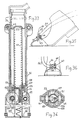
- Figures 35 and 36 show a mode, also non-limiting embodiment of the joint 6 on the front part of the shoe.
- the aim sought in joint 6 is to allow large angular movements around an axis substantially perpendicular to the median plane of the body and to prohibit the rotational movements with a vertical axis which could lead to striking the arm 5d with the ankle or the shoe or the bottom of the calf.
- the rotational movement of the foot about a horizontal axis substantially perpendicular to the median plane of the body, therefore substantially perpendicular to the longitudinal axis of the foot and substantially parallel to the ground, is obtained by means of axis 63, extending the junction arm 5, which can rotate freely in a bore of a cylindrical part 64.
- the assembly and disassembly of the axis 63 in the part 64 is done immediately by lifting or pushing the pin 65 into a hole in the part 64 which axially immobilizes the axis 63 thanks to a groove circular of it. It should be specified here that to equip the device, the individual begins by putting on shoes fitted with piece 64.
- the cylindrical part 64 has two lateral shaft sections 66 which materialize an axis of rotation perpendicular to the bore of the part 64 and substantially longitudinal with respect to the foot. These two shaft sections 66 are each housed in a bore of a part integral with the shoe and which allows them to rotate freely with a limited angular value, which allows a slight rolling movement of the foot and which makes the race more pleasant to the individual. However, if the latter is equipped with additional accessories such as ice skates or two-wheeled roller skates, it may be advantageous to completely block this roll movement with a shim placed under the piece 64 for example. As in all cases, the amplitude of roll movement authorized by the device is low, this allows in varied terrain to preserve the individual from an ankle fracture thanks to the torsional rigidity of the arm 5 and to the device telescopic.
- the fixing of the bores receiving the shaft sections 66 on the front part of the shoe can be carried out in many ways.
- Figures 35 and 36 show one of them which is a hollow metal part preferably or hard plastic, surrounding the end of an ordinary shoe and fixed under its sole.
- the invention may also include other provisions such as for example the fixing of the axis 63 at the level of the sole, especially in the case where the interested party generally uses skates simultaneously and that he does not need rolling motion.
- the axis 63 can be fixed directly in the accessory, skate or ski, possibly used.
- the location of the axis 63 relative to the length of the foot is variable depending on the uses. It also takes into account the bending stiffness of the shoe. The only common point is that this implantation is in the front part of the foot or possibly in front of it, in order to concern the greatest possible geometric deformation during the extension of the leg and the foot which cause the propulsion of the body.
- junction arm 5d shown in top view relative to the foot in FIG. 37 and in profile in FIG. 2 is designed as a function of the following elements: compatibility with the dimensions and displacements of the lower part of the leg and of the foot, which leads to having it preferably outside the legs and not between the legs and adaptation of the sections to the value of the local bending moment. Furthermore, the arm 5 has in profile a preferably curved shape with a concavity towards the ground in order to make it less vulnerable to obstacles.
- the material constituting the junction arm 5 can be a steel with high mechanical performance or a light alloy or a composite material with an organic matrix, provided that in the latter two cases, the junction with the articulation 4 and in particular with the ratchet of blocking is done by a high-performance steel insert, the axis 63 of the articulation 6 also having to remain in steel.
- junction arm 5 is not limiting of the invention and it is possible that the shapes thereof must be adapted, either for the preferential use of an accessory such as skate, ski, etc. or to a particular type of disability.
- Figures 38 to 45 describe embodiments of the lockable and unlockable joint 4.
- the described joint is in all cases a right joint of the individual which is symmetrical to the left joint.
- this layout is not not limiting of the invention because it is obvious that it is possible on the one hand to place the articulation 4 slightly above the lower end of the telescopic system and on the other hand, to place it more forward or further back , in relation to the direction of walking of the individual, from the position in which it is represented.
- junction arm 5 would simply be shorter or longer and the part of the articulation 4 integral with the telescopic device would be connected to the latter by a rigid arm. It is also possible, with an appropriate form of junction arm, to use a U-joint crossed by an axis, in which the end of the arm 5 forms the U and where the telescopic device is in the center of the U. All kinds of variants constructive are therefore possible in the context of the overall invention.
- the joint 4 When the foot is placed in front of the body on the ground and until all effort has ceased, that is to say approximately until the detachment of the ground from the foot located at the rear, the joint 4 remains blocked and all the efforts undergone or exerted by the telescopic system pass through it. At the end of the efforts, the articulation 4 must allow the instantaneous rise of the foot therefore the reduction of the angle made by the junction arm 5 with the telescopic device 3. For this, it is therefore necessary that the ratchet system is put temporarily out of service.
- the articulation 4 is provided with an adjustable stop which makes it possible to adjust the maximum opening angle between the junction arm 5 and the telescopic system 3 so that, when this angle is reached, the effort that makes the foot, lowering forward, is transmitted to the telescopic devices 3 and then lengthens these while compressing their return spring.
- the adjustment of the stop allows among other things to adapt to a certain extent the device to the size of an individual.
- the stopper is provided with a pre-stressed spring.
- the downward force to be applied by the foot via the articulation 6 is greater than that which was necessary to put the telescope in maximum extension and fully compress its return spring.
- the compression of the stop spring therefore represents a certain overshoot of the maximum angle between the arm 5 and the telescope 3, provided by the adjustment of the stop, this overshoot can only take place if the telescopic device 3 is already in position d 'maximum extension.
- Another role of the joint 4 is to ensure that the ratchet system cannot operate while the stop spring is compressed and that consequently the opening of the angle of the arm 5 and of the telescope 3 exceeds a value provided by the chosen stop setting.
- This latter role results in advantages concerning the adaptability of the apparatus according to the invention to various kinds of reliefs, various speeds, various types of race with or without leaping and various types of additional accessories such as skates, etc. .. Indeed, this last improvement allows in certain cases to stop the mechanical assistance to the propulsion of the leg on average a little before the end of the rear stride, if desired, and to finish the stride without mechanical assistance . In this way, the end of the stride is felt in a softer and more natural way by the individual.
- the means enabling the lockable joint 4 to fulfill the roles assigned to it are as follows, but these are not not limiting of the invention.
- Other ratchet systems can be implemented as well as other ratchet decommissioning systems.
- the adjustable and shock-absorbing stop system which can also put the ratchet out of service is a very useful improvement, but not absolutely compulsory.
- the only mandatory aspect is to have a means of blocking and unblocking this joint.
- the arm 5d is connected, for example by welding to a cylindrical base 67 provided with a closure plate 68.
- the base 67 comprises a collar on which comes to bear a nut 67a screwed on the other part of the joint, but not blocked, and braked by the screw 67b.
- the base 67 is provided with an axial toothing 69 which cooperates with an axial toothing 70 of the cylindrical ratchet 71 visible in FIGS. 39, 41, 43, 44.
- the ratchet 71 can therefore slide axially in the cylindrical base 67 and it transmit a very high torque in the absence of axial movements.
- the cylindrical ratchet 71 also carries, on one end face of a radial toothing with an asymmetrical profile 72 which cooperates with an identical toothing 73 cut on the base 74 of the articulation 4 which is integral, for example by welding, of the lower part 3i of the telescopic device.
- the asymmetry of the teeth 72 and 73 maintained in contact by the spring 75 which exerts an axial thrust on the ratchet and its extension allows the rotation of the articulation 4 in one direction and not in the other as explained above: the 5d arm can therefore be lowered, the individual being standing, and cannot go up.
- axial teeth 69 could be integral with the base 74 and that the radial teeth 73 could on the contrary be integral with the base 67. This arrangement is within the scope of the invention.
- cylindrical ratchet 71 Another role of the cylindrical ratchet 71 is to transmit the efforts for angular abutment of the joint 4 thanks to the three asperities 76. These cooperate with three asperities 77 of a part 78 visible in FIGS. 39 and 45 in section general circular which can rotate freely in the base 74 to which it is axially linked by the nut 78a. The circular ratchet 71 therefore tends to drive the part 78 in rotation as soon as the roughness 76 meets the roughness 77.
- the part 78 is provided with a lug 79 visible in FIGS. 39 and 42, the role of which is to press on the stop 80 which is a cylindrical cage holding the stop spring 81 in the prestressed position.
- the base of this spring presses on a nut 82 cooperating with a threaded rod 83 to which it communicates the thrust of the lug 79, and this rod 83 transmits it to the cylindrical cage 84 welded to the base 74.
- the initial fulcrum can be moved between the lug 79 and the stop 80 upwards, which influences the angular position of the stop.
- FIG. 42 represents the stop 80 in the maximum downward adjustment position.
- the release of the articulation by axial displacement of the cylindrical ratchet 71 can also be carried out without relation to the angular stop from a hydraulic or electro-magnetic or electro-mechanical force with devices which are described in FIGS. 38 to 40. These devices require an arrival of fluid or electric current delivered by a control system which will be described later. It is also possible to produce an entirely mechanical and unmanned release system, which, based on the measurement of the flexion of the junction arm 5 under the effect of the torque, releases the articulation 4 as soon as the propulsion force by the telescopic devices 3 ceases, therefore at the end of the individual's rear stride.
- FIG. 38 shows a first principle for generating the axial displacement of the cylindrical ratchet 71.
- the latter contains a solenoid 89 which, when it is traversed by a direct current, moves to the right around the ferrous core 90 secured to the plate d obturation 68 of the base 67.
- the electric current is brought by a wire 91 which comes through a hole 92 in the end plate of the lower or female part 3i of the telescopic device.
- FIG. 39 shows a second principle for generating the axial displacement of the cylindrical ratchet 71.
- An electric motor 93 with direct current is fixed by its outer cage to the base 74.
- the rotor 94 thereof is secured to a nut 95 which can rotate in plain bearings of the outer cage of the motor 93 but which cannot move axially relative to it.
- This nut rotates around a threaded rod 96 which is immobilized in rotation by a pin 97 bearing on the base 74.
- the rotation of the nut 95 therefore causes the axial displacement of the threaded rod 96, which contains a shaft 98 integral with the cylindrical ratchet 71 and constantly pushed to the left by a spring 75.
- FIG. 40 shows a third principle for generating the axial displacement of the cylindrical ratchet 71.
- a part integral with the ratchet 71 constitutes a piston 98a which can move without a cylinder 99 integral with the base 74.
- the displacement to the left takes place with the return spring 75 of the ratchet.
- the movement to the right is effected by the action of a hydraulic thrust, either directly in the volume limited by the cylinder 99 and the head of the piston 98, or by the intermediary of a flexible bladder 100 to have better sealing.
- the arrival of fluid takes place by paths analogous to those followed by the electric wires and which will be described later, together with the means intended to generate the currents or the fluid pressures at the desired times.
- FIGS. 46 to 50 describe principles of generation and distribution of fluids under pressure intended to produce a mechanical extension force in those of telescopic devices 3 which are equipped with an axially extensible sealed chamber.
- the two global systems described use a positive displacement compressor and a heat engine controlled by a regulator which controls the power demanded at the average pressure that the pilot wishes to have in a buffer tank.
- a small electric generator is associated with the heat engine.
- All of these elements are well known to those skilled in the art, are not limitative of the invention and will not be described here, although there are particularly favorable provisions for the use of them. invention in subject.
- Stirling cycle external combustion engines for example, will be slightly heavier, very preferable to internal combustion engines which are much noisier.
- FIGS. 46 to 49 uses a liquid as transfer fluid and the system in FIG. 50 uses a gas which is, a priori, air.
- a gas which is, a priori, air.
- the invention is not limited by the use of any particular liquid or gas, possibly including a combustion gas.
- the driving power is very variable according to the uses preferentially envisaged for the device but it is in principle in the range from 1 to 10 KW, the majority of the applications requiring 2 to 5 KW.
- a powerful motor-compressor group with the tanks and the distributor, will weigh from 4 to 8 kg approximately without the fuel, which is the mass order of magnitude of manual forest chainsaws. In the case of the invention, this mass being fixed to the body is very easy to transport.
- the order of magnitude of the maximum compressor outlet pressures is generally in the range 5 to 50 bars depending on the section of the cylinders used and the type of use sought, so that a volumetric type compressor is normally necessary.
- These pressures pose no problem for the use of flexible pipes, the nature of which is well known to those skilled in the art need not be described and the machining details required for the control drawers are of very high value. common in hydraulic equipment.
- This distributor 105 is actuated in turn in one direction and in the other by the solenoids 108 and 109 respectively.
- the 110 g and 110 d lines connect the distributor to the deformable sealed chamber contained in the left and right telescopic system respectively. They lead to grooves 111 and 112 which can communicate with the drawer 106.
- the pipe 113 connects the buffer tank 103 to the wall of the cylinder in which the drawer 107 slides.
- the latter has a groove 114 which can be put, when it occupies its extreme axial positions in relation to the pipes 115 connected together and when it occupies its two intermediate axial positions, in relation to the pipe 113.
- the groove 114 is connected by the passage 116 to the groove 117 which can communicate with the drawer 106
- the drawer 107 is provided at each of its ends with a spring 118 whose length in the absence of contact is known with precision and with an asperity 119 which is used to push the drawer 106 in one direction or the other.
- a fourth groove 120 surrounds the drawer 106 and can communicate with it. It is connected by line 121 to a tank 122 which is at atmospheric pressure. From this tank leaves a pipe 123 which ends in the pipe 115 by a non-return valve 124. The pipe 115 is also connected to the inlet of a damping and partial energy recovery tank 125 which has a deformable membrane 126 behind which there is compressed air.
- Figure 12 corresponds to the position of the drawers 106 and 107 shown in Figure 46: the line 110 g receives the liquid from the left telescope 3g and the drawer 106 sends it through the line 121 in the atmospheric pressure tank 122 n ' therefore offering no resistance to the ascent of the left telescope which will continue in FIGS. 13, 14 and as far as FIG. 15 under the action of its return spring 39 or 61.
- the pipe 110d which made it possible to send the fluid coming from the reservoir 122 via the pipe 123, the non-return valve 124, the pipe 115, the groove 114, the passage into the right telescope 3d during its elongation prior to FIG. 12 116, the groove 117, the drawer 106 and the groove 112, starts from FIG. 12 and until FIG. 15 to receive the fluid which comes from the right telescope which is shortened and to send it in the pipe 115 where a part will be sucked in by the compressor through line 127 and where another part will go into the damping-recovery tank 125 where it will compress the compressed air by deforming the membrane 126.
- the role of the compressed air spring is therefore to dampen the and store the quantity of fluid under pressure brutally discharged by the 3d telescope that the compressor could not pump quickly enough, but that it would pump just after.
- FIG. 15 corresponds to the moment when the drawer 107 passes from the position it occupied in FIG. 46 to that which it occupies in FIG. 47. There was simply a cut in the current of the electromagnet 108 which maintained compressed the spring 118 which is on the left in the figure. This relaxing caused the movement of the drawer 107 without moving the drawer 106.
- the passage 116 and the groove 117 are no longer in relation to the pipe 115 but with the pipe 113 which makes it possible to send into the 3d telescope the pressurized fluid which provides the individual with the driving force to assist propulsion by his right leg.
- the buffer tank 103 can contain, if necessary and very schematically, two deformable membranes 128 and 129 behind which are respectively compressed air and a gas or gas mixture of the family of freons for example, which is or are in temperature and pressure conditions very close to their liquid-gas balance.
- the role of mixtures of freons or other gases close to the temperature and pressure conditions of their liquid-gas equilibrium is to attenuate the pressure differences observed as a function of the extension of the telescopes.
- the most desirable law of pressure variation can be brought into play for comfort and efficiency.
- FIG. 16 which is the end of the propulsive stride by the right leg corresponds to the passage to the position of the drawers represented in FIG. 48.
- the solenoid 109 moves the drawer 107 all the way, which on the one hand moves the drawer 106 by action of the tip 119, on the other hand, fully compresses the spring 118 which is to the right of the figure and finally puts the groove 114 in relation to the pipe 115.
- This allows, as can be seen, the emptying of the fluid contained in the right telescope whose extreme extension position is reached and its sending by the pipe 110d, the groove 120, the drawer 106 and the pipe 121 in the tank 122.
- FIG. 49 is the last of the possible positions of the drawers following the interruption of the current in the solenoid 109. It corresponds to FIG. 47 by reversing the positions of the right and left telescopes.
- Figure 18 which corresponds to the start of application of the body weight on the right leg is the moment when the distributor passes, by cutting the electric current, from the position of Figure 46 to that of Figure 47.
- the only change is the relaxation of the spring 118 located to the left of the drawer 107 in the figure, which puts the groove 114 of this drawer in relation to the pipe 113 and closes the pipe 120.
- the telescopic device of the right leg is supplied with the liquid under pressure from the buffer tank.
- the position of the drawer 106 has not moved relative to the position in FIG. 46, therefore the emptying of the liquid contained in the telescopic device 3g of the left leg can continue towards the reservoir 122.
- FIG. 19 corresponds to the position of the distributor that can be seen in FIG. 47.
- the position of the distributor becomes that which can be seen in FIG. 48.
- the foot left is already in contact with the ground, but it does not yet support the weight of the body.
- the body weight is carried on the left foot in a position identical to that described in FIG. 18 for the right foot, and at this moment, the distributor takes the position described in FIG. 49, which admits the driving pressure in the telescopic device 3g of the left leg.
- FIGS. 46 to 49 makes it possible to distribute power: on the one hand, according to the law of variation of desired pressure thanks to the buffer tank 103 and its annexes with air or perfect gas 128 or gas close to gas-liquid balance 129.
- the system described in FIGS. 46 to 49 makes it possible to distribute power: on the one hand, according to the law of variation of desired pressure thanks to the buffer tank 103 and its annexes with air or perfect gas 128 or gas close to gas-liquid balance 129.
- the pumping time at maximum flow rate of the compressor 104 thanks to the tank 122 containing a perfect air or gas tank 126.
- the hydraulic circuit can also be adapted to multiple specific applications.
- Figure 50 is shown a principle of generation, distribution and recovery of compressed air. If the gas used is air, small leaks are unimportant, which allows the use of less expensive equipment.
- the system described in FIG. 50 comprises, as well as that of FIG. 46, a motor 101, a regulator 102, a displacement compressor 104a sending the compressed air into a buffer tank 103 which can be provided with a gas tank at l gas-liquid balance separated by a flexible membrane 129 not shown.
- the distributor 105a is provided with two drawers 106 and 107 similar to those of the distributor 105 and operating in the same way.
- This distributor 105 has been described by analogy with the system of FIG. 46, but better passage sections can be obtained in practice by separating the right distribution from the left distribution with a 3-way solenoid valve each telescopic device connected to the pipe. 110g or 110d and in turn to pipe 113 or 130.
- the distributor 106 is in relation to the right and left telescopic devices by the pipes 110g and 110d respectively, leading to the grooves 111 and 112 located around it.
- the groove 117 is also reserved for feeding when it is in relation to the buffer tank 103 by the pipe 113 and the groove 120 is reserved for emptying-recovery.
- the groove 114 of the drawer 107 is not in communication with any orifice when this drawer occupies its two extreme positions and is in communication with the pipe 113 when it occupies its two intermediate positions.
- FIG. 50 which corresponds, for the arrangement of the drawers in relation to the position of the legs, to FIG. 46 or to FIG. 48 by inverting the name of the legs, more precisely represents the start of the draining recovery of the telescopic device 3g of the left leg.
- the system described therefore allows very rapid emptying of the telescopic device concerned, by recovering, following losses and intermediate detents of the order of two thirds of the expansion energy from the air.
- this system or a system having the same purpose, is generally not necessary unless it is compulsory for the applications targeted for the apparatus to drain the telescopic devices very quickly.
- the drain pipe 130 is simply connected to the pipe 127 for admission to the compressor and the recovery efficiency is improved.
- no duct is provided for filling air at atmospheric pressure when the right leg descends.
- the device can include: - Either a fully automatic piloting system during operation, certain options concerning it can be optionally chosen before departure, - Either an automatic pilot with manual correction of the settings while walking, - Or at least partially manual control during walking, reserved for slow-paced uses.
- adjustments can be made when stationary to encourage the use of the device on a certain type of route.
- adjustments can be made when stationary to encourage the use of the device on a certain type of route.
- These are for example the adjustment of the stop screw 85 of the articulation 4 or the adjustment of the electric stop screw 164 located on the control of the drawer 107 of the distributor, or the gas pressures located behind the flexible membranes 128, 129 of the buffer tanks 103 or storage-recovery tank 125.
- the elements or functions of the device which must be controlled are at least, the release of the articulation 4, the authorization to relock the articulation 4, the filling and emptying of the tight and expandable volumes of the telescopic devices 3 if the device includes one and the pressure from the buffer tank 103 controlling the engine speed if the device has one.
- the complete piloting system includes: - physical data sensors - a system for processing this data - mechanical execution devices for orders received by the system - a control system accessible to the individual and the annexes which link him to the data processing system or which act directly on the nature of the physical data - wires or tubes connecting all the above elements.
- the first of the sensors is that which detects the arrival at the maximum extension stop of the telescopic systems.
- the senor 137 or the like can optionally detect an extension position of the telescopic device 3 which does not correspond to its maximum extension position but which is located chronologically a little before.
- the sensor 137 can be replaced by a permanent detection system of the extension position of the telescopic device 3.
- a system can be easily accommodated for example in the cavity existing inside the pistons 55 and 36 as seen in Figures 33 and 29. It can consist, for example, of a telescopic system provided with axially arranged magnetic signals, or measuring an electrical resistance proportional to the elongation.
- the length of the mechanically assisted part of the extension of the foot is defined by the adjustment of the stop 80 with the screw 85, possibly motorizable, but the detection of the telescopic elongation is another means of adjusting the length of the driving part of the extension and gradually lengthen the stride when you start. In this case, it is simply necessary to adapt the control circuits described in FIGS. 52 to 55.
- the type 137 sensor or the like can on the one hand trigger an electrical signal, as in the diagrams in FIGS. 53 to 55 or a hydraulic signal as in FIG. 52, which in both cases control the release of the articulation 4 by end of propulsive stride to allow the foot to rise.
- the second detection system is composed of one or more sensors 138 moving on one or more tracks 139 composed of one or more fractions of circular crown centered on the axis of the joint 11 of the saddle and fixed for example on the middle partition thereof. This second system is visible in FIGS. 21 to 28 and 51 to 55.
- the sensors 138 can also move radially on the track 139.
- this second detection system is to make it possible to synchronize certain piloting orders either with a particular angular position of the telescopic devices 3 with the saddle or between them such as, for example, the crossing of the legs represented in FIG. 15, or with the extreme angular displacement of the legs, the latter being of variable amplitude at the discretion of the user.
- track 139 can be replaced by magnetic signaling fixed on it and cooperating with an appropriate sensor 138, these systems being well known to those skilled in the art. .
- This sensor 138b has a wiper 145 which has an anchoring end 146 which, cooperating with an appropriate housing, integral with the body of the sensor 138b, allows it to turn slightly in the plane of the figure and to move vertically downwards when it leaves the thickest part of track 139.
- the wiper 145 cannot, however, rub on the thinner part of track 139.
- the wiper 145 is pushed by an oblique spring 147 which, resting on the body of the sensor 138b exerts on it a force downwards and to the left of FIG. 55. Thus, if the sensor 138b moves to the left of FIG.
- this assembly can be transformed into an electric rheostat comprising an insulated wiper and a track 139 electrically insulated from the middle partition 19 of the saddle 1 , thus playing the role of variable resistance. It is then easy to permanently electrically determine the value of the mathematical derivative of a current flowing through the system. The zero derivative then corresponds to the point of change of direction.
- This rheostatic system also makes it possible to eliminate the geometric discontinuities on track 139 since it suffices to replace them with a measurement of the electrical resistance of the circuit. This also simplifies piloting because it is possible to avoid moving track 139 to modify the angular position of the reference frame. It suffices that the conductor displays a value of his choice for the new critical resistance of the rheostatic system.
- the general layout of the sensors and detectors 137 and 138 is visible in FIG. 51.
- connection between the sensor 138, the sensor 137 and the articulation 4 can be carried out in the following two ways, taking into account the telescopic movement between the parts 3i and 3s.
- connection starting from the location of the sensor 138 can be a wire or flexible tubular helical conduit 152 disposed inside the upper part. 3s of the telescopic device, penetrating into the head of the piston integral with the lower part 3i of the telescopic device, connecting the sensor 137, and then descending to the base of the lower part 3i by a conduit drilled in the piston rod 36r or 49r.
- connection starting from the location of the sensor 138 can be a flexible tubular wire or conduit 153 descending in a longitudinal groove, not visible in the diagrams, of the upper part 3s of the telescopic device up to its junction with the part 53 where this wire leaves its groove is connected to a sensor 137 and then enters a hollow cylindrical lower extension 154 of the support part 58 of the return spring 61, passing between the rollers 50 and 51. Then the flexible wire or conduit 153 takes the form of a helicoid and descends inside the split tube 57 to the bottom of the lower part 3i of the telescopic device.
- detector sensors are also not limiting of the invention. In particular, it may be envisaged to take an interest in complementary or replacement physical signals in the case where the invention or its variants are applied to very specific use cases.
- the first function to be fulfilled by the elements of the automatic piloting system is the release and authorization to re-block the joint 4.
- the release of this joint always takes place towards the end of the propulsive stride of the leg concerned and therefore , at the end of the extension stroke of the telescopic device 3 or almost at the end of it.
- the driver of the device has a possibility of mutual adaptation of these elements according to the terrain or the speed thanks to the screw 85 for adjusting the abutment of the joint 4 and to the possibility of being able to detect a slightly precursor signal of the extension stop of the telescopic device 3.
- the articulation is released at the end of the movement shown in FIG. 16 or FIG. 20.
- the resetting authorization that is to say the ability for the cylindrical ratchet 71 to prevent the raising of the arm 5 after the latter has come down from any angle less than or equal, however, to the angle defined by the stop screw 85, is given at the time when the ascent of the foot which will first rest on the ground is maximum. This practically leads to giving this authorization at about the moment when the foot which will land on the ground exceeds by going forward the foot which is on the ground, therefore in the position of FIGS. 15 and 19 approximately.
- the caster of the sensor 138 a which acts on a hydraulic piston or a flexible bladder, can move, when the foot is in front of the body with respect to the direction of travel on the thinner part of track 139 and, when the foot is behind the body on the thickest part of track 139.
- the quantity of liquid contained in the sensor 138a is therefore minimal.
- the stop sensor 137 comes to a stop, its hydraulic piston or its flexible bladder eject a quantity of liquid which can therefore only go into the cavity 100 and push the piston 98a into the cylinder 99. This causes the unlocking of the articulation 4 as seen in FIG. 40.
- Figure 53 an electrical system with battery whose principle is absolutely similar to that of the hydraulic system.
- the stop sensor 137 establishes a contact on the circuit
- the contact of the sensor 138a is established since the wheel is on the thick part of the track 139, therefore the electromagnet 89 bearing on the core 90 unlocks the articulation 4 as seen in FIG. 38.
- the action of this electromagnet is suppressed by the break contact 138a after the crossing of the feet, which restores the initial role of the ratchet 71.
- control mechanism consists in sending a direct current in the first direction to the motor to obtain the release of the joint 4 and a direct current in the opposite direction to obtain the authorization to re-block the latter.
- the track 139 has only an asperity corresponding to the position of the caster of the sensor 138a at the moment when the rear foot which is raised exceeds by going forward the foot which is on the ground.
- the roughness of the track 139 establishes a double contact 157 and 158 which sends a direct current pulse in the motor 93 in the opposite direction to that which was sent to it. by the sensor 137, therefore the joint 4 is replaced in the possible locking position.
- the second function to be fulfilled by the elements of the automatic piloting system is the emptying and supplying of fluid to the deformable sealed volumes contained in the telescopic devices 3.
- the emptying of the telescopic devices begins at the end of the individual's propulsive stride, therefore corresponding to the end of the operation described in FIGS. 16 and 20, and therefore in the vicinity of the maximum expansion of the telescopic devices 3.
- the automatic supply of pressurized fluid to telescopic devices depends a lot, unlike emptying, on how the device is used.
- the supply is carried out by the distributor 105 or 105a, by means of two drawers 106 and 107 whose operation has been explained: the displacement of the drawer 106 is obtained by sending current in one of the solenoids 108 or 109 which cause the maximum axial displacement of the drawer 107, which drives the drawer 106 and places it in the emptying position of one of the telescopic devices.
- the admission can take place in the other telescopic device only when the current is cut in the electromagnet concerned.
- a sensor 137 belonging for example to the right side of the apparatus according to the invention establishes contact in the electromagnet 108 to drain the right telescope, it is sensor 138b on the right side and the track 139 on the right side that will depend on the power cut in the electromagnet 108 therefore the admission of fluid in the left telescope.
- the individual user of the device can move as shown in Figures 12 to 17, that is to say in a more or less accentuated leaping mode performed flat or uphill. It can also move as shown in Figures 18 to 20, that is to say in such a way that after the foot has touched the ground forward, there is a need for immediate or almost immediate feeding of the telescopic device connected to this stand.
- the interruption of the current in the electromagnet 108 will not be due in these two use cases to the same physical parameter.
- the cut will be due to the passage of the wiper 145 of the sensor 138b over a discontinuity in thickness of the track 139 and in the second case, the cut will be due to the reversal of the direction of friction of the wiper 145 on the runway 139.
- the operating diagram in Figure 55 takes into account all these intermediate contingencies and extreme cases.
- the adjusting screw 164 is loosened down as much as possible so that the contacting of the wiper 145 on the stopper 148 cannot cut the current because the flexible conductive blade 149 can descend on its inclined plane of support and contact.
- the individual With the manual correction means of the autopilot, composed of a handle 144 sending with a separate electrical circuit pulses on the stepping motor 143, the individual has the means to move the position of the discontinuity of the track 139. Consequently, if it moves the track to the left of the figure, the power cut will each time be obtained automatically earlier, therefore the power supply of the opposite telescope will take place earlier, which will encourage for example the rise of a hill in leaping mode.
- the adjusting screw 164 is tightened up before departure to prevent the flexible conductive blade 149 from going too low on its inclined plane of contact and contact.
- the sensor 138b which is directed towards the left of the figure while maintaining its wiper 145 in contact with the blade 149, reverses its movement and goes towards the right, the contact is cut instantly or almost instantaneously depending on the length of course on the inclined plane that the adjustment of the screw 164 will allow the blade 149.
- the individual can also climb very steep stairs or slopes without this latter system and using the previous device with an appropriate adjustment of the position of the discontinuity of runway 139 provided that it moves at a certain speed, therefore with a sharper movement of the scissors.
- the second device is only intended to increase the precision in certain cases which are generally infrequent in use.
- the adjustment movements by the screws 164 are described here very schematically and they can be motorized to allow continuous manual interventions on the autopilot.
- This parameter is set independently of the other aspects of piloting the device by means of a manual control grouped on the same handle as the contactor 160 and the control 144 for adjusting the automatic intake.
- This handle rotating in two directions, or / and provided with push buttons as the case may be, can be simply held in the hand and connected to the device by a bundle of flexible wires. It can also be secured to the device like the support handles 180 which will be seen later.
- This command which displays the desire of the individual for a higher or lower pressure in the buffer tank 103 intervenes directly on the regulator 102 which controls the power of the engine to the average pressure chosen for the tank 103 whatever the required flow rate , within the possible limits, by telescopic devices 3.
- the use of the device is thus without danger since the individual progressively increases the pressure of the reservoir 103 according to the needs and possibilities of a given route and taking into account his physical skills.
- Figures 57 to 62 relate to some variants made to the apparatus according to the invention.
- Figures 56 and 57 describe a mechanical assistance system for the scissor movement of the legs, that is to say the pendulum movement of telescopic devices 3.
- This system uses the whole apparatus according to the invention and therefore constitutes a simple addition on it without any modification of the previously described provisions.
- each of the telescopic devices 3 is connected by a hinge 167 to a telescopic jack 166, an opposite articulation 168 of which is connected to a fixed point sufficiently integral with the saddle and situated behind it.
- the articulation 168 is fixed to the base of the powertrain 7 but this is not limiting.
- the cylinders 166 have pistons 169 whose stroke is sufficient not to impede the complete pendulum movements of each of the telescopic devices 3.
- the supply of compressed fluid to the cylinders 166 is very simple because each of them is connected to the pipe d supply of the left or right telescopic device which is opposite it with respect to the median partition of the saddle.
- This line 171 is connected to the atmosphere if the propulsion fluid is of the compressed area, and it is connected to a valve 172 located at the inlet of the other cylinder 166 if the propulsion fluid is a liquid.
- the control of the solenoid valves 170 is carried out by means of a contact established by the sensor 137 previously described.
- the device according to the invention when the device according to the invention is fitted with jacks 166, it also includes the three conical wheels 25d, 25g and 26 which ensure the maintenance of the angular position of the saddle 1.
- the face 174 of the pistons 173 can exert pressure on a liquid which causes the two cylinders 166 to communicate via the line 175.
- the advance of one of the pistons 173 is necessarily accompanied identical recoil from the other piston 173, which gives a certain angular stabilization between the saddle and the bisector of the angle formed at all times by the two telescopic devices 3.
- Figures 58 and 59 describe in side view and in back view, the apparatus according to the invention fitted to an individual.
- the device has in this case two types of additional supports with the body, these two elements can be used independently of one another.
- the normal support transmitting the ascending forces produced by the device is the saddle 1.
- These efforts therefore concern the bottom of the individual's spine.
- the means described in Figures 58 and 59 are intended to also relate to the top of the spine by an ascending action exerted either on the hands, or under the shoulders, or in two places at the same time.
- the advantage is, for a normal person, to distribute the efforts received in several points instead of only one which can increase comfort especially if the power of the device is high and, for a disabled person, to compensate for a deficiency of the spine.
- the fact of using a shoulder support connected by a rigid bar to the saddle 1 makes it possible to give, if necessary for certain uses, additional degrees of stabilization to the saddle relative to the body.
- the suspension under the shoulders comprises a support means 176 which can be a metal or plastic bar section, more or less flattened, to adapt well to the shape of the back and end in concave parts upward passing under the shoulders.
- the piece 176 could also end up above the shoulders and support them by belts passing under the arms or any other appropriate means.
- the set can also be completed with a strap passing in front of the chest to increase stability.
- the part 176 has, generally in its middle, a hinge 177 whose axis is substantially parallel to the ground and longitudinal with respect to the body. This joint can be blocked for certain uses.
- This joint comprises a longitudinal axis with respect to the saddle and the body and substantially parallel to the ground and an axis perpendicular to the median plane of the saddle.
- the articulation 179 allows the bar 178 to exert no torque on the saddle but as said above, it may be advantageous for certain uses of the device that the bar 178 can exert a torque on the saddle to keep it in position. Consequently, the two axes of the joint 179 can be locked, simultaneously or separately.
- the possible blocking means are sufficiently known to those skilled in the art that they need not be described.
- the suspension by the hands comprises two handles 180 arranged symmetrically with respect to the body a few centimeters outside the thighs.
- the axis of these handles 180 is substantially parallel to the ground when the device is mounted on the individual who is standing and these handles are substantially parallel to each other.
- They are securely connected to the rear of the saddle by curved metal or plastic tubes 181 which bypass the back of the thighs of the individual leaving the free movement of these.
- the curved tubes 181 are fixed on the resistant structure of the rear of the saddle by a means which also allows an angular position adjustment around an axis perpendicular to the median plane of the saddle.
- This means can be composed for example of a collar nut which comes to block against the male threaded part, integral with the saddle, a collar with radial teeth practiced on the end of each tube 181.
- the individual can adapt the height of the handles to the length of its arms to be in the position most favorable to the transmission by them of a significant vertical force.
- One or both of the handles can also play the role of steering controls like a motorcycle handle if the device includes a motor-compressor unit.
- Figures 60 and 61 describe two variants of the telescopic device 3 according to the invention. They relate only to the way of making sliding possible in the presence of a couple but the other functions of these telescopic devices, that is to say the application of an extension force by a spring or a fluid and the return springs are produced by adapting the principles already described and will not be repeated.
- the joints on the saddle and the lockable and unlockable joint 4 are also identical to those of the nominal telescopic device 3 as well as the means for implementing the steering.
- FIG. 60 there is a rigid metal bar 182 starting from the joints of the saddle and ending at a joint 183 with an axis substantially perpendicular to the median plane of the body.
- the joint 183 is connected to a metal plate 184 which carries the lockable and unblockable joint 4 and a joint 185 with an axis substantially perpendicular to the median plane of the body.
- the articulation 185 is connected to a male or female sliding part of a telescopic jack 186, the other male or female sliding part of which is connected by an articulation 187 with an axis substantially perpendicular to the median plane of the body to the bar 182.
- FIG 61 there is a rigid metal bar 188 starting from the joints of the saddle and ending at a joint 189 with an axis substantially perpendicular to the median plane of the body.
- the joint 189 is connected to a metal plate 190 which carries the lockable and unlockable joint 4 and a joint 191 with an axis substantially perpendicular to the median plane of the body.
- the articulation 191 is connected to a male or female sliding part of a telescopic jack 192, the other male or female sliding part of which is connected by an articulation 193 with an axis substantially perpendicular to the median plane of the body to the bar 188.
- the bars 182 or 188 and the plates 184 or 190 to which they are articulated are a means of replacing the casters of the telescopic devices 3 previously described and that they make it possible to obtain the propulsion force under the effect of the expansion of the telescopic jack 186 or the shortening of the telescopic jack 192 without these having to undergo a torque.
- These two methods which involve greater forces in the cylinders require larger sections for them than for those described so far and they are relatively bulky.
- the telescopic cylinders 186 or 188 are more easily adaptable to this use, intended for example for certain infirm.
- the lockable and unlockable articulation 4 by a rigid fixing of the junction arm 5 on the telescopic device because the use then generally only includes sufficiently slow movements. It is also possible to block the articulation 6 so as to make the shoe integral with the arm 5.
- FIG. 62 represents an additional means for allowing the rotation of the foot around the axis of the legs with the apparatus according to the invention.
- the junction arm 5 is provided with an articulation 194 with an axis substantially perpendicular to the ground and which is located near the articulation 4.
- This process can allow wider technical choices to be made for the telescopic devices 3 with casters of FIGS. 29 to 34, if they no longer have the obligation to ensure a mutual rotation of the sliding parts around their longitudinal axis. It can be applied in particular, as well as any other process playing the same role and fixed at the base or at the top of the telescopic devices, in the case where the sliding is not straight or in the case of the telescopic devices of FIGS. 60 and 61 .
- the first solution consists in connecting a portable compressed air tank at very high pressure, fitted with a holder, directly on the pipe 113 of FIG. 50.
- the expansion energy is then not recovered and the evacuation takes place. done in the open air by the pipe 130.
- the autonomy in elevation is short and it depends on the proportion of mechanical propulsion work that is required of the device compared to the work provided by the legs. On the other hand, the distance traveled is not limited.
- the second solution consists in supplying the pipe 113 of FIG. 50 by a long and thin flexible pipe which permanently supplies compressed air coming from a stationary source.
- the sources of compressed air are very common in factories or various sites so that it is easy for the worker carrying the device and having to carry out locally a painful work of ascent, to connect his flexible hose nearby .
- the autonomy in elevation and in distance covered is relatively low but the work required can thus continue indefinitely.
- This means can be advantageously used by the physically handicapped to climb a staircase because it is easy to bring down the flexible hose of compressed air in the middle of the stairwell as small as it is and a priori regardless of the number of floors.
- the physically impaired, able for example to walk, like a big heart, but not able to climb a staircase may constantly leave a personal device reserved for this use in the vicinity of the staircase that he will have to take often.
- the third solution consists in equipping the apparatus with a motor-compressor group with an electric motor and in supplying the latter with a flexible wire, under conditions identical to the cases of use of a flexible hose of compressed air.
- the fourth solution which uses electrical energy, provided by a flexible wire, or for a very short autonomy, by a portable battery, requires a technological variant on the mode of exercise of the extension force in the devices.
- telescopic 3 The explanation, very simple, refers to the existing drawings.
- the axis of this motor is therefore parallel to that of the telescopic device 3s and at a distance such that the external dimensions of the motor allow just the passage of the female or lower part 3i of the telescopic device when it slides.
- the electric motor is therefore fixed only by its upper end to the reduction gear with parallel gears, itself fixed to the upper end of the part 3s of the telescopic device.
- the arrangement of this motor, below the level of the top of the part 3s does not increase the vertical size of the latter at the small thickness near the reduction gear with parallel gears.
- the pendulum travel of the telescopic devices 3 therefore remains sufficient.
- This mode of exercising the extension force of the telescopic devices 3 therefore requires a left and a right electric motor, but all the devices shown in FIGS. 46 and 50 are eliminated. Motors, screws and ball nuts perform extension and shortening movements telescopic devices.
- the types of control possible are directly derived from those described above and shown in Figures 51 to 55.
- the joints 6 are then fixed to the top of rigid cavities with thin walls made of sheet metal or plastic into which the toe of the shoes can be pushed in which is slightly stuck there thanks to an interior coating in foam rubber of these cavities for example.
- the device then behaves more or less as if the joints 6 were rigidly connected with the shoe.
- the saddle 1 then does not have a fastening device 2 on the hips.
- it is provided with two lateral handles 180 which are sufficient to keep it in contact with the body for a short time.
- the device according to the invention can also operate without a motor like a seat in an indifferent vertical position allowing certain painting work to be carried out, etc.
- the transmission of forces by liquid is then used.
- a reservoir 103 contains, behind a flexible bladder 129 or a system of pistons, a quantity of gas found for the temperature and the pressures concerned under conditions close to its liquid-gas equilibrium.
- the change in volume thereof is accompanied by a small variation in pressure, which which allows to exert on a piston contained in the telescopic device 3 a relatively constant force throughout the course of the latter and to have a seat to raise indifferent.
Landscapes
- Health & Medical Sciences (AREA)
- Engineering & Computer Science (AREA)
- General Health & Medical Sciences (AREA)
- Life Sciences & Earth Sciences (AREA)
- Public Health (AREA)
- Physical Education & Sports Medicine (AREA)
- Animal Behavior & Ethology (AREA)
- Veterinary Medicine (AREA)
- Mechanical Engineering (AREA)
- Pain & Pain Management (AREA)
- Epidemiology (AREA)
- Robotics (AREA)
- Rehabilitation Therapy (AREA)
- Nursing (AREA)
- Orthopedic Medicine & Surgery (AREA)
- Biomedical Technology (AREA)
- Heart & Thoracic Surgery (AREA)
- Vascular Medicine (AREA)
- Pulmonology (AREA)
- Rehabilitation Tools (AREA)
- Footwear And Its Accessory, Manufacturing Method And Apparatuses (AREA)
Applications Claiming Priority (2)
| Application Number | Priority Date | Filing Date | Title |
|---|---|---|---|
| FR8516097 | 1985-10-30 | ||
| FR8516097A FR2589360B1 (fr) | 1985-10-30 | 1985-10-30 | Appareil d'assistance mecanique de la propulsion par les jambes |
Publications (1)
| Publication Number | Publication Date |
|---|---|
| EP0229537A1 true EP0229537A1 (de) | 1987-07-22 |
Family
ID=9324343
Family Applications (1)
| Application Number | Title | Priority Date | Filing Date |
|---|---|---|---|
| EP86402375A Withdrawn EP0229537A1 (de) | 1985-10-30 | 1986-10-23 | Vorrichtung zur mechanischen Unterstützung der Vorwärtsbewegung durch die Beine |
Country Status (3)
| Country | Link |
|---|---|
| US (1) | US4872665A (de) |
| EP (1) | EP0229537A1 (de) |
| FR (1) | FR2589360B1 (de) |
Cited By (3)
| Publication number | Priority date | Publication date | Assignee | Title |
|---|---|---|---|---|
| GB2260495A (en) * | 1991-10-04 | 1993-04-21 | Steeper Hugh Ltd | Orthotic or prosthetic walking brace |
| FR2874317A1 (fr) * | 2004-08-19 | 2006-02-24 | Univ Jean Monnet | Dispositif pour assujettir une ou plusieurs articulation(s) d'un membre du corps humain |
| US11071675B2 (en) * | 2019-01-14 | 2021-07-27 | Northeastern University | Lower limb exoskeleton system having jump-down cushioning function and method of using the same |
Families Citing this family (104)
| Publication number | Priority date | Publication date | Assignee | Title |
|---|---|---|---|---|
| US4967734A (en) * | 1987-08-31 | 1990-11-06 | Rennex Brian G | Energy-efficient running brace |
| US5011136A (en) * | 1988-11-09 | 1991-04-30 | Rennex Brian G | Energy-efficient running brace |
| SE463600B (sv) * | 1989-05-11 | 1990-12-17 | Ken Petersen | Metod och apparat foer led-kontrollerad traening av olika motoriska enheter |
| DE69019154D1 (de) * | 1989-07-05 | 1995-06-08 | Applied Motion Int | Fortbewegungsgerät mit zwei pedalen für den menschen. |
| US5016869A (en) * | 1989-07-05 | 1991-05-21 | Applied Motion | Human bipedal locomotion device |
| US5176377A (en) * | 1991-02-19 | 1993-01-05 | Wilkinson William T | Coordinated arm-leg aerobic walking exercise device |
| US5658242A (en) * | 1991-03-13 | 1997-08-19 | Polycane Australia Pty Ltd. | Walking aid |
| WO1992016177A1 (en) | 1991-03-13 | 1992-10-01 | Polycane Australia Pty. Ltd. | Walking aid |
| IL105034A (en) * | 1993-03-12 | 1998-03-10 | Sate Of Israel Ministry Of Def | Exoskeletal system |
| US5362288A (en) * | 1993-03-26 | 1994-11-08 | Eli Razon | Device for assisting running, walking or jumping |
| US5716330A (en) * | 1995-07-13 | 1998-02-10 | Goldman; David A. | Body and limb position/motion detector and power assist apparatus and method |
| US6312398B1 (en) * | 1996-12-26 | 2001-11-06 | The United States Of America As Represented By The Administrator Of The National Aeronautics And Space Administration | Actuator for flexing a resilient covering |
| WO1999034875A1 (en) * | 1998-01-05 | 1999-07-15 | Laurcath Corporation | Body mounted muscle exercise apparatus and method |
| US6666796B1 (en) * | 1999-09-16 | 2003-12-23 | Aerovironment, Inc. | Walking assisting apparatus |
| RU2170566C1 (ru) * | 2000-07-07 | 2001-07-20 | Качесов Владимир Александрович | Способ выпрямления и облегчения вертикализации больных и устройство для его осуществления |
| US20020094919A1 (en) * | 2000-07-26 | 2002-07-18 | Rennex Brain G. | Energy-efficient running aid |
| US6409693B1 (en) | 2001-01-22 | 2002-06-25 | Robert J. Brannigan | Leg support device |
| US6401864B1 (en) * | 2001-01-31 | 2002-06-11 | Bil-Jax, Inc. | Collapsible stabilizing devices |
| JP3643867B2 (ja) * | 2001-07-23 | 2005-04-27 | 独立行政法人情報通信研究機構 | マニピュレータの制御方法 |
| US20040053755A1 (en) * | 2002-07-03 | 2004-03-18 | Wilkinson William T. | Power walker |
| US6966882B2 (en) | 2002-11-25 | 2005-11-22 | Tibion Corporation | Active muscle assistance device and method |
| CN1238076C (zh) * | 2003-05-07 | 2006-01-25 | 李荣德 | 女性阴道肌肉锻炼器 |
| WO2005025464A2 (en) * | 2003-09-11 | 2005-03-24 | The Cleveland Clinic Foundation | Apparatus for assisting body movement |
| US7628766B1 (en) * | 2003-10-29 | 2009-12-08 | The Regents Of The University Of California | Lower extremity enhancer |
| US20050227833A1 (en) * | 2004-04-02 | 2005-10-13 | Wilkinson William T | Wearable exercise apparatus |
| US7571839B2 (en) * | 2004-05-19 | 2009-08-11 | Hrl Laboratories, Llc | Passive exoskeleton |
| US7445138B2 (en) * | 2004-05-19 | 2008-11-04 | Conrad Chu | Passive exoskeleton |
| US7645246B2 (en) * | 2004-08-11 | 2010-01-12 | Omnitek Partners Llc | Method for generating power across a joint of the body during a locomotion cycle |
| US20060046910A1 (en) * | 2004-08-11 | 2006-03-02 | Rastegar Jahangir S | Methods and devices for reducing stance energy for rehabilitation and to enhance physical performance |
| US7278979B2 (en) * | 2004-09-07 | 2007-10-09 | Honda Motor Co., Ltd. | Walking assistance device having a pelvis support member that is easy to wear |
| US7261679B2 (en) * | 2004-09-17 | 2007-08-28 | Jason M Sload | Runner training and exercise device |
| JP4344314B2 (ja) * | 2004-12-28 | 2009-10-14 | 本田技研工業株式会社 | 体重免荷アシスト装置および体重免荷アシストプログラム |
| US20070123997A1 (en) * | 2005-03-31 | 2007-05-31 | Massachusetts Institute Of Technology | Exoskeletons for running and walking |
| US20060249315A1 (en) | 2005-03-31 | 2006-11-09 | Massachusetts Institute Of Technology | Artificial human limbs and joints employing actuators, springs, and variable-damper elements |
| US10307272B2 (en) | 2005-03-31 | 2019-06-04 | Massachusetts Institute Of Technology | Method for using a model-based controller for a robotic leg |
| US20070043449A1 (en) | 2005-03-31 | 2007-02-22 | Massachusetts Institute Of Technology | Artificial ankle-foot system with spring, variable-damping, and series-elastic actuator components |
| US11278433B2 (en) | 2005-03-31 | 2022-03-22 | Massachusetts Institute Of Technology | Powered ankle-foot prosthesis |
| US8512415B2 (en) | 2005-03-31 | 2013-08-20 | Massachusetts Institute Of Technology | Powered ankle-foot prothesis |
| AU2006236579B2 (en) * | 2005-04-13 | 2011-09-22 | The Regents Of The University Of California | Semi-powered lower extremity exoskeleton |
| CA2598091C (en) * | 2005-05-27 | 2011-04-12 | Honda Motor Co., Ltd. | Walking assistance device |
| EP1905406B1 (de) * | 2005-05-27 | 2012-10-24 | Honda Motor Co., Ltd. | Gehhilfsvorrichtung |
| KR100855538B1 (ko) * | 2005-05-27 | 2008-09-01 | 혼다 기켄 고교 가부시키가이샤 | 보행 보조 장치 |
| CN1868434B (zh) * | 2005-05-27 | 2011-12-28 | 本田技研工业株式会社 | 行走辅助装置的控制装置 |
| EP1902700B1 (de) * | 2005-05-27 | 2011-10-19 | Honda Motor Co., Ltd. | Gehhilfsvorrichtung |
| JP4588666B2 (ja) * | 2005-05-27 | 2010-12-01 | 本田技研工業株式会社 | 歩行補助装置の制御装置および制御プログラム |
| JP4641225B2 (ja) * | 2005-07-19 | 2011-03-02 | 本田技研工業株式会社 | 歩行補助装置 |
| US7297090B2 (en) * | 2005-09-20 | 2007-11-20 | Serafino Torres | Personal exercise device |
| US7731674B2 (en) * | 2006-06-29 | 2010-06-08 | Honda Motor Co., Ltd. | Walking assistance device |
| US7578799B2 (en) * | 2006-06-30 | 2009-08-25 | Ossur Hf | Intelligent orthosis |
| JP4712627B2 (ja) * | 2006-07-10 | 2011-06-29 | 本田技研工業株式会社 | 歩行補助装置 |
| JP5047692B2 (ja) * | 2006-08-22 | 2012-10-10 | 本田技研工業株式会社 | 歩行補助装置 |
| JP4745167B2 (ja) * | 2006-08-22 | 2011-08-10 | 本田技研工業株式会社 | 歩行補助装置 |
| JP4620012B2 (ja) | 2006-08-22 | 2011-01-26 | 本田技研工業株式会社 | 歩行補助装置 |
| US8353854B2 (en) | 2007-02-14 | 2013-01-15 | Tibion Corporation | Method and devices for moving a body joint |
| JP4989278B2 (ja) * | 2007-04-05 | 2012-08-01 | パナソニック株式会社 | 下肢パワー増幅装置 |
| EP2163226A1 (de) * | 2007-04-23 | 2010-03-17 | Golden Crab, S.L. | Exoskelett zur sicherheit und kontrolle beim schifahren |
| CA122632S (en) * | 2007-04-27 | 2008-09-29 | Honda Motor Co Ltd | Walking support |
| JP4789117B2 (ja) * | 2007-08-03 | 2011-10-12 | 本田技研工業株式会社 | 歩行補助装置 |
| JP4784771B2 (ja) * | 2007-10-01 | 2011-10-05 | 本田技研工業株式会社 | 歩行補助装置 |
| JP4654447B2 (ja) * | 2007-12-19 | 2011-03-23 | 本田技研工業株式会社 | 歩行補助装置 |
| WO2009099671A2 (en) | 2008-02-08 | 2009-08-13 | Tibion Corporation | Multi-fit orthotic and mobility assistance apparatus |
| CA2724085C (en) | 2008-05-20 | 2018-10-16 | Berkeley Bionics | Device and method for decreasing energy consumption of a person by use of a lower extremity exoskeleton |
| US20090306548A1 (en) | 2008-06-05 | 2009-12-10 | Bhugra Kern S | Therapeutic method and device for rehabilitation |
| US9351855B2 (en) | 2008-06-16 | 2016-05-31 | Ekso Bionics, Inc. | Powered lower extremity orthotic and method of operation |
| WO2010011848A1 (en) * | 2008-07-23 | 2010-01-28 | Berkeley Bionics | An exoskeleton and method for controlling a swing leg of the exoskeleton |
| US8274244B2 (en) | 2008-08-14 | 2012-09-25 | Tibion Corporation | Actuator system and method for extending a joint |
| US8058823B2 (en) * | 2008-08-14 | 2011-11-15 | Tibion Corporation | Actuator system with a multi-motor assembly for extending and flexing a joint |
| CA130421S (en) * | 2008-10-30 | 2010-03-10 | Honda Motor Co Ltd | Walking support system |
| JP5073642B2 (ja) * | 2008-12-17 | 2012-11-14 | 本田技研工業株式会社 | 動作補助装置 |
| JP5213682B2 (ja) * | 2008-12-17 | 2013-06-19 | 本田技研工業株式会社 | 体重支持装置 |
| US20100198124A1 (en) * | 2009-01-30 | 2010-08-05 | Kern Bhugra | System and method for controlling the joint motion of a user based on a measured physiological property |
| US8639455B2 (en) | 2009-02-09 | 2014-01-28 | Alterg, Inc. | Foot pad device and method of obtaining weight data |
| FR2942587B1 (fr) * | 2009-02-27 | 2012-04-20 | Hubert Fievet | Chaussure de ski permettant de supporter au moins en partie le poids d'un skieur et ensemble chaussures de ski et skis associe. |
| WO2011094649A1 (en) * | 2010-01-28 | 2011-08-04 | Rick Farnsworth | Treadmill resistance training apparatus |
| US20130158445A1 (en) * | 2010-08-23 | 2013-06-20 | The Regents Of The University Of California | Orthesis system and methods for control of exoskeletons |
| JP5841787B2 (ja) * | 2011-02-25 | 2016-01-13 | 川崎重工業株式会社 | 装着型動作支援装置 |
| JP5212957B1 (ja) * | 2011-05-16 | 2013-06-19 | 安男 石黒 | 椅子として兼用できる靴 |
| JP1449444S (de) * | 2011-10-27 | 2015-08-17 | ||
| KR101360727B1 (ko) * | 2011-12-14 | 2014-02-10 | 현대자동차주식회사 | 전동식 개인이동장치 |
| US9221177B2 (en) | 2012-04-18 | 2015-12-29 | Massachusetts Institute Of Technology | Neuromuscular model-based sensing and control paradigm for a robotic leg |
| JP2014104185A (ja) * | 2012-11-28 | 2014-06-09 | Sony Corp | 運動補助装置及び運動補助方法 |
| WO2014151584A1 (en) | 2013-03-15 | 2014-09-25 | Alterg, Inc. | Orthotic device drive system and method |
| US9407125B2 (en) * | 2013-06-21 | 2016-08-02 | Queen's University At Kingston | Biomechanical electrical power generation apparatus |
| CN105899176B (zh) * | 2014-01-15 | 2018-07-20 | 松下电器产业株式会社 | 作业姿势保持装置 |
| JP2015208795A (ja) * | 2014-04-24 | 2015-11-24 | パナソニック株式会社 | 動作支援装置 |
| CN104000708B (zh) * | 2014-06-19 | 2016-11-16 | 陕西科技大学 | 一种辅助上、下楼梯的行走装置 |
| JP6386269B2 (ja) * | 2014-06-30 | 2018-09-05 | 本田技研工業株式会社 | 歩行補助装置 |
| US9393173B1 (en) * | 2015-03-12 | 2016-07-19 | Javier Meza | Rehabilitation and walking assisting assembly |
| US20180296426A1 (en) * | 2015-10-16 | 2018-10-18 | Rewalk Robotics Ltd. | Apparatuses, systems and methods for controlling exoskeletons |
| FR3046744B1 (fr) * | 2016-01-15 | 2020-02-28 | Robotiques 3 Dimensions | Exosquelette avec jambes telescopiques a l’arriere. |
| JP6315031B2 (ja) * | 2016-06-28 | 2018-04-25 | ソニー株式会社 | 運動補助装置及び運動補助方法 |
| CN106377399B (zh) * | 2016-11-16 | 2017-07-28 | 广州初曲科技有限公司 | 一种模拟神经电信号的增强型智能仿生助力机械腿 |
| KR102023239B1 (ko) * | 2017-01-19 | 2019-09-19 | 박동관 | 중첩 식 외다리 휴대용 작업의자 |
| DE102017131319B4 (de) * | 2017-12-27 | 2019-07-04 | Otto Bock Healthcare Products Gmbh | Orthopädietechnische Einrichtung und Verfahren zu deren Steuerung |
| US11992453B2 (en) * | 2018-10-15 | 2024-05-28 | Honda Motor Co., Ltd. | Tensile force generating device and bending and stretching motion assist device provided with same |
| KR102762504B1 (ko) * | 2018-12-27 | 2025-02-06 | 삼성전자주식회사 | 착용형 의자 |
| WO2020139115A1 (ru) * | 2018-12-28 | 2020-07-02 | Игорь Александрович ОРЛОВ | Способ поддержания позы человека и системы для осуществления способа |
| US20220339778A1 (en) * | 2019-05-02 | 2022-10-27 | Mawashi Science & Technology Inc. | Body weight support system for exoskeletons and method of using the same |
| CN110787429B (zh) * | 2019-12-05 | 2024-08-16 | 南京燕智谷智控科技有限公司 | 台阶缓冲踏板 |
| RU198080U1 (ru) * | 2019-12-20 | 2020-06-17 | Максим Геннадьевич Мощенко | Механический экзоскелет для нижних конечностей |
| RU198079U1 (ru) * | 2019-12-20 | 2020-06-17 | Максим Геннадьевич Мощенко | Механический экзоскелет для нижних конечностей |
| CN111920650B (zh) * | 2020-09-28 | 2021-01-08 | 上海傅利叶智能科技有限公司 | 一种旋转缓冲助力机构和外骨骼踝关节缓冲助力装置 |
| CN112193348A (zh) * | 2020-12-02 | 2021-01-08 | 哈尔滨工业大学(威海) | 一种仿生关节式气动弹跳腿 |
| EP4268908B1 (de) * | 2022-04-28 | 2025-12-03 | Space Applications Services NV/SA | Exoskelett, verfahren zum bereitstellen gegenläufiger linearer translatorischer kräfte durch exoskelettkinematik und verwendung eines exoskeletts |
Citations (3)
| Publication number | Priority date | Publication date | Assignee | Title |
|---|---|---|---|---|
| DE247482C (de) * | ||||
| DE846891C (de) * | 1950-07-20 | 1952-08-18 | Angelo Grisoni | Kuenstlicher Fuss |
| DE3227359A1 (de) * | 1981-07-24 | 1983-02-10 | Otto Bock, Orthopädische Industrie KG, 3428 Duderstadt | Einrichtung zum feststellen eines drehgelenkes |
Family Cites Families (10)
| Publication number | Priority date | Publication date | Assignee | Title |
|---|---|---|---|---|
| US440684A (en) * | 1890-11-18 | Apparatus for facilitating walking | ||
| US406328A (en) * | 1889-07-02 | Peters | ||
| US2111018A (en) * | 1935-08-13 | 1938-03-15 | Ahler George William | Walking brace |
| US2210269A (en) * | 1938-02-01 | 1940-08-06 | Byron M Taylor | Means to aid in regaining normal body locomotion |
| US3529474A (en) * | 1968-12-05 | 1970-09-22 | Albert M Olson | Cardiac exerciser |
| GB1310492A (en) * | 1968-12-05 | 1973-03-21 | Flowtron Aire Ltd | Apparatus for activating parts of the body |
| US3976057A (en) * | 1974-12-23 | 1976-08-24 | Clarence F. Bates | Joint flexing apparatus |
| CH593056A5 (en) * | 1975-06-24 | 1977-11-15 | Valutec Ag | Seat to assist disabled person to stand - has power cylinder controlled by operating handle to swing up seat and backrest |
| US4557257A (en) * | 1983-07-21 | 1985-12-10 | Fernandez Jose M | Pneumatic walking brace and operating system |
| US4651719A (en) * | 1985-01-22 | 1987-03-24 | Danninger Medical Technology, Inc. | Continuous passive motion shoulder unit |
-
1985
- 1985-10-30 FR FR8516097A patent/FR2589360B1/fr not_active Expired
-
1986
- 1986-10-16 US US06/920,072 patent/US4872665A/en not_active Expired - Fee Related
- 1986-10-23 EP EP86402375A patent/EP0229537A1/de not_active Withdrawn
Patent Citations (3)
| Publication number | Priority date | Publication date | Assignee | Title |
|---|---|---|---|---|
| DE247482C (de) * | ||||
| DE846891C (de) * | 1950-07-20 | 1952-08-18 | Angelo Grisoni | Kuenstlicher Fuss |
| DE3227359A1 (de) * | 1981-07-24 | 1983-02-10 | Otto Bock, Orthopädische Industrie KG, 3428 Duderstadt | Einrichtung zum feststellen eines drehgelenkes |
Cited By (5)
| Publication number | Priority date | Publication date | Assignee | Title |
|---|---|---|---|---|
| GB2260495A (en) * | 1991-10-04 | 1993-04-21 | Steeper Hugh Ltd | Orthotic or prosthetic walking brace |
| GB2260495B (en) * | 1991-10-04 | 1996-02-07 | Steeper Hugh Ltd | An orthotic or prosthetic walking brace |
| FR2874317A1 (fr) * | 2004-08-19 | 2006-02-24 | Univ Jean Monnet | Dispositif pour assujettir une ou plusieurs articulation(s) d'un membre du corps humain |
| WO2006021729A1 (fr) * | 2004-08-19 | 2006-03-02 | Universite Jean Monnet | Dispositif pour assujettir une ou plusieurs articulation(s) d'un membre du corps humain |
| US11071675B2 (en) * | 2019-01-14 | 2021-07-27 | Northeastern University | Lower limb exoskeleton system having jump-down cushioning function and method of using the same |
Also Published As
| Publication number | Publication date |
|---|---|
| FR2589360B1 (fr) | 1987-12-24 |
| US4872665A (en) | 1989-10-10 |
| FR2589360A1 (fr) | 1987-05-07 |
Similar Documents
| Publication | Publication Date | Title |
|---|---|---|
| FR2589360A1 (fr) | Appareil d'assistance mecanique de la propulsion par les jambes | |
| EP3283037B1 (de) | Bewegungsassistenzvorrichtung | |
| US5378214A (en) | Self-powered human centrifuge | |
| TWI607921B (zh) | 腳踏車及相關聯部件 | |
| JP3282077B2 (ja) | 人力駆動機構 | |
| WO2014134362A1 (en) | Snowmobile with leaning capability | |
| CA1125807A (fr) | Trottinette | |
| EP3137368B1 (de) | Antriebseinheit und kompaktes personenfahrzeug | |
| FR2920952A1 (fr) | Creation d'un pied artificiel et controle de son mouvement | |
| FR2608933A3 (fr) | Appareil d'exercice physique et de divertissement | |
| WO2005000433A1 (fr) | Appareil roulant pour utilisateurs de patins a roulettes | |
| CA2290097C (fr) | Preuves que contraction du mollet ne peut pas augmenter la pression sur la pedale et mecanismes mettant a profit cette decouverte fondamentale | |
| EP1383585A1 (de) | Autonomes mechanisches rollendes fortbewegungsmittel welches an jeden fuss eines wanderers anpassbar ist | |
| WO2018078274A1 (fr) | Vehicule individuel a faible encombrement | |
| CN100581910C (zh) | 没有把手的脚推进的轮式运动装置 | |
| US12053429B2 (en) | Walker specialized for trail use | |
| FR2735439A1 (fr) | Appareil de deplacement a patins mobiles et bras pivotants | |
| GB2374843A (en) | Rider propelled pedal vehicle with pedestrian supervised control | |
| WO2018165733A1 (en) | Bicycle with seat extender and pedal support | |
| EP3251729B1 (de) | Struktur für körperliche übungen der unteren gliedmassen in einem flüssigen milieu | |
| GB2195298A (en) | A transport cart for one or two persons and or goods | |
| WO2024161285A1 (en) | Wheeled vehicle | |
| US202665A (en) | Improvement in velocipedes | |
| CA2509917A1 (fr) | Vehicule actionne par le poids de l'utilisateur | |
| FR2722163A1 (fr) | Dispositif oscillant de transformation de l'energie musculaire en energie mecanique, notamment pour la propulsion de bicyclettes |
Legal Events
| Date | Code | Title | Description |
|---|---|---|---|
| PUAI | Public reference made under article 153(3) epc to a published international application that has entered the european phase |
Free format text: ORIGINAL CODE: 0009012 |
|
| AK | Designated contracting states |
Kind code of ref document: A1 Designated state(s): AT BE CH DE ES GB GR IT LI LU NL SE |
|
| 17P | Request for examination filed |
Effective date: 19870806 |
|
| 17Q | First examination report despatched |
Effective date: 19890331 |
|
| STAA | Information on the status of an ep patent application or granted ep patent |
Free format text: STATUS: THE APPLICATION IS DEEMED TO BE WITHDRAWN |
|
| 18D | Application deemed to be withdrawn |
Effective date: 19900703 |