EP0229680B1 - Verfahren zur Lippeneinstellung einer Breitschlitzdüse für schichtförmiges Material und hierfür verwendete Extrusionslippe - Google Patents
Verfahren zur Lippeneinstellung einer Breitschlitzdüse für schichtförmiges Material und hierfür verwendete Extrusionslippe Download PDFInfo
- Publication number
- EP0229680B1 EP0229680B1 EP87200023A EP87200023A EP0229680B1 EP 0229680 B1 EP0229680 B1 EP 0229680B1 EP 87200023 A EP87200023 A EP 87200023A EP 87200023 A EP87200023 A EP 87200023A EP 0229680 B1 EP0229680 B1 EP 0229680B1
- Authority
- EP
- European Patent Office
- Prior art keywords
- cooling
- bar shaped
- extrusion die
- characteristic
- shaped elements
- Prior art date
- Legal status (The legal status is an assumption and is not a legal conclusion. Google has not performed a legal analysis and makes no representation as to the accuracy of the status listed.)
- Expired - Lifetime
Links
- 238000001125 extrusion Methods 0.000 title claims description 55
- 238000000034 method Methods 0.000 title claims description 14
- 239000000463 material Substances 0.000 title claims description 8
- 238000001816 cooling Methods 0.000 claims description 72
- 238000010438 heat treatment Methods 0.000 claims description 21
- 239000002826 coolant Substances 0.000 claims description 18
- 238000005485 electric heating Methods 0.000 claims description 3
- 239000004020 conductor Substances 0.000 claims 1
- 239000003570 air Substances 0.000 description 3
- 238000005259 measurement Methods 0.000 description 3
- 239000011248 coating agent Substances 0.000 description 2
- 238000000576 coating method Methods 0.000 description 2
- 230000000694 effects Effects 0.000 description 2
- 239000011344 liquid material Substances 0.000 description 2
- 230000005855 radiation Effects 0.000 description 2
- 239000012080 ambient air Substances 0.000 description 1
- 230000004888 barrier function Effects 0.000 description 1
- 239000002131 composite material Substances 0.000 description 1
- 230000006835 compression Effects 0.000 description 1
- 238000007906 compression Methods 0.000 description 1
- 239000007788 liquid Substances 0.000 description 1
- 239000000203 mixture Substances 0.000 description 1
- 238000012986 modification Methods 0.000 description 1
- 230000004048 modification Effects 0.000 description 1
- XLYOFNOQVPJJNP-UHFFFAOYSA-N water Substances O XLYOFNOQVPJJNP-UHFFFAOYSA-N 0.000 description 1
Images


Classifications
-
- B—PERFORMING OPERATIONS; TRANSPORTING
- B29—WORKING OF PLASTICS; WORKING OF SUBSTANCES IN A PLASTIC STATE IN GENERAL
- B29C—SHAPING OR JOINING OF PLASTICS; SHAPING OF MATERIAL IN A PLASTIC STATE, NOT OTHERWISE PROVIDED FOR; AFTER-TREATMENT OF THE SHAPED PRODUCTS, e.g. REPAIRING
- B29C48/00—Extrusion moulding, i.e. expressing the moulding material through a die or nozzle which imparts the desired form; Apparatus therefor
- B29C48/25—Component parts, details or accessories; Auxiliary operations
- B29C48/30—Extrusion nozzles or dies
- B29C48/305—Extrusion nozzles or dies having a wide opening, e.g. for forming sheets
- B29C48/31—Extrusion nozzles or dies having a wide opening, e.g. for forming sheets being adjustable, i.e. having adjustable exit sections
- B29C48/313—Extrusion nozzles or dies having a wide opening, e.g. for forming sheets being adjustable, i.e. having adjustable exit sections by positioning the die lips
-
- B—PERFORMING OPERATIONS; TRANSPORTING
- B29—WORKING OF PLASTICS; WORKING OF SUBSTANCES IN A PLASTIC STATE IN GENERAL
- B29C—SHAPING OR JOINING OF PLASTICS; SHAPING OF MATERIAL IN A PLASTIC STATE, NOT OTHERWISE PROVIDED FOR; AFTER-TREATMENT OF THE SHAPED PRODUCTS, e.g. REPAIRING
- B29C48/00—Extrusion moulding, i.e. expressing the moulding material through a die or nozzle which imparts the desired form; Apparatus therefor
- B29C48/03—Extrusion moulding, i.e. expressing the moulding material through a die or nozzle which imparts the desired form; Apparatus therefor characterised by the shape of the extruded material at extrusion
- B29C48/07—Flat, e.g. panels
- B29C48/08—Flat, e.g. panels flexible, e.g. films
-
- B—PERFORMING OPERATIONS; TRANSPORTING
- B29—WORKING OF PLASTICS; WORKING OF SUBSTANCES IN A PLASTIC STATE IN GENERAL
- B29C—SHAPING OR JOINING OF PLASTICS; SHAPING OF MATERIAL IN A PLASTIC STATE, NOT OTHERWISE PROVIDED FOR; AFTER-TREATMENT OF THE SHAPED PRODUCTS, e.g. REPAIRING
- B29C48/00—Extrusion moulding, i.e. expressing the moulding material through a die or nozzle which imparts the desired form; Apparatus therefor
- B29C48/25—Component parts, details or accessories; Auxiliary operations
- B29C48/92—Measuring, controlling or regulating
-
- B—PERFORMING OPERATIONS; TRANSPORTING
- B29—WORKING OF PLASTICS; WORKING OF SUBSTANCES IN A PLASTIC STATE IN GENERAL
- B29C—SHAPING OR JOINING OF PLASTICS; SHAPING OF MATERIAL IN A PLASTIC STATE, NOT OTHERWISE PROVIDED FOR; AFTER-TREATMENT OF THE SHAPED PRODUCTS, e.g. REPAIRING
- B29C2948/00—Indexing scheme relating to extrusion moulding
- B29C2948/92—Measuring, controlling or regulating
- B29C2948/92504—Controlled parameter
- B29C2948/92609—Dimensions
- B29C2948/92647—Thickness
-
- B—PERFORMING OPERATIONS; TRANSPORTING
- B29—WORKING OF PLASTICS; WORKING OF SUBSTANCES IN A PLASTIC STATE IN GENERAL
- B29C—SHAPING OR JOINING OF PLASTICS; SHAPING OF MATERIAL IN A PLASTIC STATE, NOT OTHERWISE PROVIDED FOR; AFTER-TREATMENT OF THE SHAPED PRODUCTS, e.g. REPAIRING
- B29C2948/00—Indexing scheme relating to extrusion moulding
- B29C2948/92—Measuring, controlling or regulating
- B29C2948/92504—Controlled parameter
- B29C2948/92704—Temperature
-
- B—PERFORMING OPERATIONS; TRANSPORTING
- B29—WORKING OF PLASTICS; WORKING OF SUBSTANCES IN A PLASTIC STATE IN GENERAL
- B29C—SHAPING OR JOINING OF PLASTICS; SHAPING OF MATERIAL IN A PLASTIC STATE, NOT OTHERWISE PROVIDED FOR; AFTER-TREATMENT OF THE SHAPED PRODUCTS, e.g. REPAIRING
- B29C2948/00—Indexing scheme relating to extrusion moulding
- B29C2948/92—Measuring, controlling or regulating
- B29C2948/92819—Location or phase of control
- B29C2948/92857—Extrusion unit
- B29C2948/92904—Die; Nozzle zone
-
- B—PERFORMING OPERATIONS; TRANSPORTING
- B29—WORKING OF PLASTICS; WORKING OF SUBSTANCES IN A PLASTIC STATE IN GENERAL
- B29C—SHAPING OR JOINING OF PLASTICS; SHAPING OF MATERIAL IN A PLASTIC STATE, NOT OTHERWISE PROVIDED FOR; AFTER-TREATMENT OF THE SHAPED PRODUCTS, e.g. REPAIRING
- B29C2948/00—Indexing scheme relating to extrusion moulding
- B29C2948/92—Measuring, controlling or regulating
- B29C2948/92819—Location or phase of control
- B29C2948/92971—Fluids, e.g. for temperature control or of environment
Definitions
- This invention relates to a method of adjusting the lip opening of an extrusion die for stratiform material, particularly for extrusion dies of the type that mainly consists of, on the one side two lips and the like, forming the lip opening, and on the other hand, a number of control units put across the width of the lip opening, which all consist of one or more bar shaped elements, expansive by heat, respectively shrinkable by cooling which act upon at least one the lips in order to displace them and to change the lip opening.
- These dies are appropriate for the extrusion of film and coating as well as for the extrusion of sheet and the like.
- extrusion die of said type is known from the U.S. patent N o . 3 940 221.
- This known extrusion die mainly consists of a die block in which an oblong opening is provided through which a more or less liquid material may be pressed by extrusion to form a layer, whereby the opening is limited on one side by a flexible lip which may be moved by expansive, respectively shrinkable, bar shaped elements in order to modify the opening width.
- the heating, respectively the cooling, of the bar shaped elements is hereby done by means of heat-conducting blocks which are provided individually for each bar shaped element, and which, parallel to the bar shaped elements, each consist of a heating element and a cooling channel.
- the cooling channels are located between the bar shaped elements and the heating elements. From this the disadvantage arises that a considerable supply of energy to the heating elements is required to provide the bar shaped elements with an encreased heat supply, opposite to the cooling.
- this known extrusion die also shows the disadvantage that the control of the lip opening is very susceptible to the changes of the ambient parameters. This is, amongst other things, due to the fact that the bar shaped elements, in order to fasten them, are in contact with the die block over a comparatively large distance, so that a considerable heat bridge is existing between the die block and these elements.
- Extrusion dies for the extrusion of stratiform materials are also known form US 4.252.519 and JP-58 65 631.
- Document JP-58 65 631 discloses a die which is of the same type as the die shown in US 3.940.221 and consequently shows the same disadvantages.
- the present invention also relates to an extrusion die for the extrusion of film, coating, sheet and the like, showing none of the said disadvantages nor other ones.
- the present extrusion die has the advantage that in the surroundings of the bar shaped elements a considerable uniformity of the temperature is reached, whereby also various temperature influences, by air currents and heat bridges, are leveled out. By this, one obtains also a uniform radiation of heat to rolls possibly positioned in the surroundings of the die, so that the disadvantage of the so called hot spots is avoided.
- Another advantage of the extrusion die according to the present invention consists in the possibility of operating with lower mean temperatures of the bar shaped elements, so that one obtains that the temperatures of the system may be adjusted in such a manner that the time constant of the cooling is almost equal to the mean time constant of the heating of the bar shaped elements. As it is known, this is a primary requirement to enable a proper control.
- the extrusion die also shows the advantage that the bar shaped elements are very well shielded against external influences, whereby it is obtained that, when the control system and/or the power supply fail the extrusion die easily may continue to operate by means of manual control.
- the extrusion die according to the invention shows also the advantage that, thanks to the method applied to control the lip opening and more specially to cool the bar shaped elements, the bar shaped elements keep receiving a sufficient cooling when one cooling channel fails.
- the extrusion die is of the type that mainly consists of, on the one side, two lips forming the lip opening, and on the other hand, a number of control units put across the width of the lip opening which all consist of at least one bar shaped element, expansive by heating, respectively shrinkable by cooling which act upon at least one of the lips in order to displace them and to change the lip opening, and whereby the method for the control mainly consists of the combination of, on the one side, the control of the heating of the bar shaped elements by each control unit in function of the local thickness checks which are carried out across the width of the formed layer of material, and one the other hand, the common cooling of several control units by forcing a cooling medium mainly transversally along several bar shaped elements.
- the temperature of the common cooling medium at the supply thereof will be controlled in combination with the said.
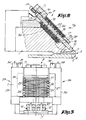
- the extrusion die consists mainly of a die block 1 showing an extrusion discharge opening 2 along which more or less liquid material 3 by means of extrusion may be pressed into a layer 4.
- the lip opening 5 of the extrusion discharge opening 2 is determined by means of two lips, respectively 6 and 7, whereby according to these embodiments the upper lip 7 is executed elastic and flexible.
- control units 8 fitted each consisting of one or more bar shaped elements, expansive by heat, respectively shrinkable by cooling which may co-operate on one end with a steady support 11, whilst they may co-operate on the other end 12 with the said elastic lip.
- the bar shaped elements 9 according to the type of embodiment, apply either a compression of or a tension on the elastic lip.
- the most important characteristic feature of the present invention consists in the control of the lip opening 5 according to a method which mainly consists in the combination of, on the one side, the control by each control unit 8 of the heating of the bar shaped elements 9, and on the other hand, the common cooling of several control units by forcing a cooling medium mainly transversely along several bar shaped elements 9.
- This movement of the cooling medium is outlined in figure 1 by means of the arrows 13 and 14.
- Another important characteristic of the preferred embodiment of the invention consists in the heating of the bar shaped elements 9 by means of heating elements 15 which are put internally in the bar shaped elements 9 and which are controlled by each control unit 8.
- two cooling blocks are employed, of several adjacent sets of each time two of such cooling blocks 16 and17 which may be fastened against each other, e.g. by means of bolts 18, thereby enclosing the bar shaped elements 9.
- each of these cooling blocks 16 and 17 are provided with opposite semicircular recesses 19 and 20 which may enclose tightly the bar shaped elements 9.
- the extrusion die is provided with means, respectively 25 and 26, to provide the supply and the discharge of a cooling medium.
- the means 25 and 26 consist of four collectors 27, 28, 29 and 30.
- the cooling channels 24 of the external cooling block 17 are connected with their inlets and outlets respectively to the collectors 27 and 28, while the cooling channels 23 of the internal cooling block 16 are connected with their inlets and outlets respectively to the collectors 29 and 30.
- Further inlets 31 and 32, as well as outlets 33 and 34 are properly provided to the said collectors in order to provide the supply and discharge of the cooling medium.
- the direction of flow of the cooling medium in the external cooling block 16 is opposite to the direction of flow of the cooling medium in the internal cooling block 16.
- the bar shaped elements 9 are fastened with their lower ends 12 and their upper ends 10 between respectively the upper lip 7 of the lip opening 5 and bolts 35 which are screwed in the steady support 11.
- the bolts 35 allow a manual adjustment of the lip opening 5.
- an insulating layer 36 is put between each internal cooling block 16 and the die block 1.
- an insulating layer may be put at the exterior, e.g. against each external cooling block 17.
- the contact surfaces between the bar shaped elements 9 and the die block 1 are preferably minimized. According to the figures 2 and 3 this realized by the application of concentric recesses 37 in the die block 1 around the bar shaped elements 9.
- the bar shaped elements 9 are internally provided with preferably electric heating elements 15 whereby, not shown on the figures, means are applied to control the supply of the electric energy to said heating elements.
- These means mainly consist of an voltage level control, an adjustable pulse generator or a frequency regulator.
- the control of the heating elements may be done according to prior art manually as well as automatically in function of the measurement of the thickness of the manufactured layer 4.
- This measurement may be realised according to the prior art by means of mechanical sensors, radiation sensitive detectors or other measuring techniques. This measurement may be executed by hand or automatically.
- the cooling medium according to the invention may be a gas or a liquid, e.g. air or water.
- the temperature of the cooling medium may be controlled.
- a temperature control is provided to the supply, e.g. a cooling device, which is not shown in the figures.
- Such a control has the advantage that one can intervene very quickly in case of an unwished disturbance. In this way, in the event that a bar shaped element 9 gets overheated, due to any possible reason, may be prevented that the lip opening 5 gets locally closed and the layer 4 is interrupted, by providing an abrupt decrease of the temperature of the cooling medium.
- transversal cooling according to the invention may occur in an other manner than described above.
- the directions of flow of the cooling medium in the cooling channels of the internal and the external cooling blocks, respectively 16 and 17, may be identical to each other.
- the transversal cooling channels may be combined at their ends in such a way that they show a course with a meander form.
- the extrusion die comprises or more single or composite cooling blocks, in other words whereby no separate internal and external cooling blocks are used. Then traverse bore holes are provided instead of the said recesses 19 and 20 into which the bar shaped elements 9 are put.
- the extrusion die may be provided with several cooling blocks which are put in juxtaposition, whereby each said cooling block e.g. may be bipartite and may consist of an internal and an external cooling block 16 and 17, either can be one-piece on itself, or may have any other shape and composition. Between the adjacent cooling blocks preferably a small free space is left, in order to allow the expansion of the cooling blocks.
- cooling channels 23 - 24 are provided, on the ends which are positioned in opposition to the bar shaped elements 9, with cooling fins which are shielded with sheets.
- the in this manner formed additionally cooling channels are fed by means of a forced air current.
- cooling blocks are provided with cooling channels which are exclusively formed by the said shielded fins.
- the heating of the bar shaped elements 9 by means of electric heating elements, and in other words it may be achieved in any manner, e.g. by means of oil or by heating by ultrasonic vibrations.
- the invention relates also to extrusion dies with several distribution channels, whereby possibly different kinds of material 3 are pressed through the same extrusion opening 2, as well as to dies which have several extrusion openings 2 adjacent to or above each other.
- the invention is also applicable with extrusion dies whereby a multi-layered extrude is formed.
Landscapes
- Engineering & Computer Science (AREA)
- Mechanical Engineering (AREA)
- Manufacturing & Machinery (AREA)
- Extrusion Moulding Of Plastics Or The Like (AREA)
Claims (17)
- Arbeitsweise für die Einstellung der Offnung der Lippe einer Strangpressmatrize für schichtenförmiges Material, wobei die Strangpressmatrize vom Typ ist, der hauptsächlich einerseits aus zwei Lippen (6-7) besteh,t die die Lippenöffnung (5) bilden, und andererseits aus einer Anzahl von über der Lippenöffnung (5) aufgestellten Steuereinheiten (3), alles zusanmengesetzt aus wenigsten einem stangenförmigen Element (9), das bei Erwärmung ausdehnt, beziehungsweise bei Abkühlung schwindet, geeignet um auf wenigstens eine der Lippen (6-7) einzuwirken um diese zu verstellen und die Lippenöffnung (5) zu ändern, dadurch gekennzeichnet, dass die Arbeitsweise der Regelung hauptsächlich besteht aus einer Kombination von, einerseits die Steuerung durch jede Steuereinheit (8) der Aufwärmung des stangenförmigen Elements (9) als eine Funktion der örtlichen Uberprüfungen der Stärke, die über die Breite des geformten schichtenförmigen Materials (4) ausgeführt werden, und andererseits, von der gemeinsamen Abkühlung verschiedener Steuereinheiten (8), durch Forzierung eines Kühlmittels hauptsachlich quergerichtet verschiedene stangenförmige Elementen entlang (9).
- Arbeitsweise nach Anspruch 1, dadurch gekennzeichnet, dass die Temperatur des zugeführten Kühlmittels gesteuert wird.
- Stranpressmatrize zur Anwendung der Arbeitsweise nach Anspruch 1 oder 2, bestehend aus der Kombination von zwei Lippen (6-1), die eine Lippenöffnung (5) bilden wo entlang das Material kontinuierlich zu einer geschichteten Form (4) gepresst werden kann, von einer Anzahl von über der Lippenöffnung (5) aufgestellten Steuereinheiten (3), alles zusammengesetzt aus wenigsten einem stangenförmigen Element (9), das bei Erwärmung ausdehnt, beziehungsweise bei Abkühlung schwindet, geeignet um mit wenigstens einer der Lippen (6-7) zusammenzuwirken um diese zu verstellen und so örtlich die Lippenöffnung (5) zu ändern, von Heizelementen (15), die jedes einzelne der stangenförmigen Elemente (9) entlang befestigt sind und von jeder der Steuereinheiten (8) gesteuert werden; und von Kühlmitteln um verschiedene Steuereinheiten (8) abzukühlen, dadurch gekenzeichnet, dass besagte Kühlmittel aus einer oder mehreren Kühlkanälen (23-24) bestehen, die sich quergericht die stangenförmigen Elemente (9) entlang ausstrecken.
- Strangpressmatrize nach Anspruch 3, dadurch gekennzeichnet, dass die Kühlkanäle (23-24) in einem Block oder in mehreren Blöcken (16-17) oder gegen einen Block oder gegen mehrere Blöcke (16-17), aus geeignetem warmeleitendem Material hergestellt, der oder die die stangenförmigen Elemente (9) umgeben, befestigt sind.
- Strangpressmatrize nach Anspruch 4, dadurch gekennzeichnet, dass die Kühlkanäle (23-24) in wenigstens einem inwendigen und/oder in wenigstens einem aussenliegenden Kühlblock (16-17) angebracht sind.
- Strangpressmatrize nach Anspruch 3 bis 5, dadurch gekennzeichnet, dass die Kühlkanäle an ihren Enden zu einer meandertförmigen Struktur kombiniert sind.
- Strangpressmatrize nach irgendwelchem der Ansprüche 4 bis 6, dadurch gekennzeichnet, dass die Kühlkanäle (23-24) in wenigstens einem Satz von zwei Kühlblöcken (16-17) angebracht sind, die gegen einander befestigt werden können, wobei sie die stangenförmigen Elemente (9) umfassen, wobei jeder einzelne dieser beiden Kühlblöcke (16-17) einerseits mit halbkreisförmigen Aussparungen versehen ist um das Umfassen der stangenförmigen Elemente (9) zu ermöglichen und andererseits mit quer zu den Aussparungen (19-20) angebrachten Aushöhlungen (21-22) und in denen die Kühlkanäle (23-24) vorgesehen sind.
- Strangpressmatrize nach irgendwelchem der Ansprüche 3 bis 6, dadurch gekennzeichnet, dass sämtliche Kühlkanäle (23-24) in einem oder mehreren gesonderten Kühlblöcken angebracht sind, wobei jeder Block mit Querbohrungen versehen ist, in die die stangenförmigen Elemente (9) eingesteckt werden.
- Strangpressmatrize nach irgendwelchem der Ansprüche 3 bis 8, dadurch gekennzeichnet, dass die Kühlkanäle (23-24) mit Kühlrippen versehen sind, die mit einer Platte bedeckt sind, wobei ein forzierter Luftstrom die Kühlrippen entlang geführt wird.
- Strangpressmatrize nach Anspruch 3, dadurch gekennzeichnet, dass die Kühlkanäle von sich auf dem Kühlblock befindenden Kühlrippen gebildet werden und die mit einer Platte bedeckt sind, wobei ein forzierter Lufstrom die Kühlrippen entlang geführt wird.
- Strangpressmatrize nach irgendwelchem der Ansprüche 3 bis 10, dadurch gekennzeichnet, dass die stangenförmigen Elemente (9) an einem Ende (10) mit einer festen Unterstützung (11) zusammenarbeiten, während sie am anderen Ende (12) mit einer der Lippen (6-7) zusammenarbeiten, wodurch die Lippenoffnung (5) beschränkt wird.
- Strangpressmatrize nach Anspruch 11, dadurch gekennzeichnet, dass wenigstens eine der Lippen (6-7) aus einer flexibelen, elastischen Lippe besteht auf die die stangenförmigen Elemente (9) mit einem Ende (12) einen Druck ausüben, während die anderen Enden (10) dieser Elemente (9) gegen die Bolzen (35) drücken, die in die feste Unterstützung (11) geschraubt sind.
- Strangpressmatrize nach Anspruch 11, dadurch gekennzeichnet, dass wenigstens eine der Lippen (6-7) aus einer flexibelen, elastischen Lippe besteht auf die die stangenförmigen Elemente (9) mit einem Ende (12) eine Kraft ausüben, während die anderen Enden (10) mit Bolzen (37) in der festen Unterstützung (11) befestigt sind.
- Strangpressmatrize nach Anspruch 12 oder 13, dadurch gekennzeichnet, dass um die stangenförmigen Elemente (9) herum konzentrische Aussparungen (37) im Matrizenblock (1) angebracht sind.
- Strangpressmatrize nach irgendwelchem der Ansprüche 3 bis 14, dadurch gekennzeichnet, dass die Heizelemente (15) inwendig in den stangenförmigen Elementen (9) angebracht worden sind.
- Strangpressmatrize nach Anspruch 15 dadurch gekennzeichnet, dass die Heizelemente (15) aus elektrischen Heizelementen bestehen.
- Strangpressmatrize nach irgendwelchem der Ansprüche 3 bis 16, dadurch gekennzeichnet, dass die Steuerung der Heizelemente (15) automatisch ausgeführt wird mittels einer Messvorrichtung, die die örtlichen Stärken über der Gesamtbreite der hergestellten Schicht (4) überwacht.
Applications Claiming Priority (2)
| Application Number | Priority Date | Filing Date | Title |
|---|---|---|---|
| BE2/60904A BE904036A (nl) | 1986-01-14 | 1986-01-14 | Werkwijze voor de regeling van de lipopening van een extrusiematrijs voor laagvormig materiaal en extrusiematrijs hierbij aangewend. |
| BE260904 | 1986-01-14 |
Publications (3)
| Publication Number | Publication Date |
|---|---|
| EP0229680A2 EP0229680A2 (de) | 1987-07-22 |
| EP0229680A3 EP0229680A3 (en) | 1989-07-26 |
| EP0229680B1 true EP0229680B1 (de) | 1992-06-03 |
Family
ID=3865783
Family Applications (1)
| Application Number | Title | Priority Date | Filing Date |
|---|---|---|---|
| EP87200023A Expired - Lifetime EP0229680B1 (de) | 1986-01-14 | 1987-01-08 | Verfahren zur Lippeneinstellung einer Breitschlitzdüse für schichtförmiges Material und hierfür verwendete Extrusionslippe |
Country Status (3)
| Country | Link |
|---|---|
| US (1) | US4726752A (de) |
| EP (1) | EP0229680B1 (de) |
| BE (1) | BE904036A (de) |
Cited By (1)
| Publication number | Priority date | Publication date | Assignee | Title |
|---|---|---|---|---|
| DE4316913A1 (de) * | 1993-05-20 | 1994-11-24 | Brueckner Maschbau | Breitschlitzdüse |
Families Citing this family (19)
| Publication number | Priority date | Publication date | Assignee | Title |
|---|---|---|---|---|
| US4781562A (en) * | 1986-08-12 | 1988-11-01 | Toshiba Kikai Kabushiki Kaisha | Heat displacing type dies |
| DE3740087A1 (de) * | 1987-11-26 | 1989-07-20 | Reifenhaeuser Masch | Verfahren zur herstellung einer folie aus thermoplastischem kunststoff mit hilfe einer breitschlitzduese |
| US5051082A (en) * | 1989-02-17 | 1991-09-24 | Mitsubishi Jukogyo Kabushiki Kaisha | Apparatus for adjusting die lips for extrusion molding |
| JPH0698671B2 (ja) * | 1989-03-30 | 1994-12-07 | トミー機械工業株式会社 | 溶融押出式フイルム成形の膜厚制御装置 |
| US5208047A (en) * | 1990-05-09 | 1993-05-04 | The Cloeren Company | Apparatus for adjusting die lip gap |
| EP0456176A3 (en) * | 1990-05-09 | 1992-03-25 | The Cloeren Company | Extrusion apparatus |
| US5020984A (en) * | 1990-05-09 | 1991-06-04 | The Cloeren Company | Apparatus for adjusting die lip gap |
| JP2767313B2 (ja) * | 1990-06-01 | 1998-06-18 | ファナック株式会社 | 射出成形機 |
| DE4041069A1 (de) * | 1990-11-09 | 1992-05-14 | Windmoeller & Hoelscher | Breitschlitzduese eines extruders |
| US5259747A (en) * | 1992-04-30 | 1993-11-09 | The Cloeren Company | Web thickness control |
| EP0625419A1 (de) * | 1993-05-19 | 1994-11-23 | The Cloeren Company | Kompensation der Temperaturvariation in Breitenrichtung |
| JP2780016B2 (ja) * | 1995-02-10 | 1998-07-23 | 井上金属工業株式会社 | 塗工装置 |
| US5674440A (en) * | 1995-05-05 | 1997-10-07 | Graham Engineering Corporation | Die head with adjustable mandrel and method |
| US5888556A (en) * | 1997-03-11 | 1999-03-30 | The Cloeren Company | Thermal translator device |
| US20030080462A1 (en) * | 2001-10-25 | 2003-05-01 | Nordgren Douglas S. | Extrusion die with horizontal and vertical extrudate opening adjustment |
| US7160094B2 (en) * | 2003-06-03 | 2007-01-09 | Avery Dennison Corporation | Die assembly |
| EP4157607B1 (de) * | 2021-04-29 | 2025-10-15 | Lohia Mechatronik Private Limited | System und verfahren zur abbildung der lippeneinstellbolzen einer flachen extrusionsdüse |
| JP7539169B2 (ja) * | 2022-09-06 | 2024-08-23 | 株式会社城北精工所 | 押出成形用ダイ |
| CN116160703B (zh) * | 2022-12-09 | 2025-08-01 | 上海复合材料科技有限公司 | 用于复合材料整流罩窗口成型模具及成型方法 |
Family Cites Families (12)
| Publication number | Priority date | Publication date | Assignee | Title |
|---|---|---|---|---|
| US2769200A (en) * | 1955-03-07 | 1956-11-06 | Dow Chemical Co | Radial extrusion die |
| US3261893A (en) * | 1962-10-04 | 1966-07-19 | Goodyear Tire & Rubber | Thermally adjusted casting blade |
| US3775035A (en) * | 1970-01-12 | 1973-11-27 | Owens Illinois Inc | Foam plastic extrusion apparatus with plurality of die lip temperature controls |
| US3920365A (en) * | 1972-08-15 | 1975-11-18 | Du Pont | Apparatus for making polymeric film |
| US3819775A (en) * | 1972-08-15 | 1974-06-25 | R Mules | Method of making polymeric film |
| US3940221A (en) * | 1973-09-10 | 1976-02-24 | Welex Incorporated | Thickness control system for an extrusion die |
| JPS5161562A (en) * | 1974-11-27 | 1976-05-28 | Teijin Ltd | Jugotaifuirumuno seizohoho |
| DE2812065C2 (de) * | 1978-03-20 | 1980-05-08 | Hermann Berstorff Maschinenbau Gmbh, 3000 Hannover | Schneckenstrangpresse mit einer Zylindertemperiereinrichtung zur Verarbeitung von thermoplastischen Kunststoffen und Kautschuk |
| US4252519A (en) * | 1979-11-16 | 1981-02-24 | Monsanto Company | Extrusion die blade |
| US4281980A (en) * | 1980-01-18 | 1981-08-04 | Monsanto Company | Expansion deformable extrusion die blade |
| US4454084A (en) * | 1982-06-09 | 1984-06-12 | Leesona Corporation | Extrusion die control system |
| JPS59182706A (ja) * | 1983-04-01 | 1984-10-17 | Matsushita Electric Ind Co Ltd | 金型接続装置 |
-
1986
- 1986-01-14 BE BE2/60904A patent/BE904036A/nl not_active IP Right Cessation
- 1986-07-10 US US06/884,086 patent/US4726752A/en not_active Ceased
-
1987
- 1987-01-08 EP EP87200023A patent/EP0229680B1/de not_active Expired - Lifetime
Cited By (1)
| Publication number | Priority date | Publication date | Assignee | Title |
|---|---|---|---|---|
| DE4316913A1 (de) * | 1993-05-20 | 1994-11-24 | Brueckner Maschbau | Breitschlitzdüse |
Also Published As
| Publication number | Publication date |
|---|---|
| US4726752A (en) | 1988-02-23 |
| BE904036A (nl) | 1986-05-02 |
| EP0229680A3 (en) | 1989-07-26 |
| EP0229680A2 (de) | 1987-07-22 |
Similar Documents
| Publication | Publication Date | Title |
|---|---|---|
| EP0229680B1 (de) | Verfahren zur Lippeneinstellung einer Breitschlitzdüse für schichtförmiges Material und hierfür verwendete Extrusionslippe | |
| US4454084A (en) | Extrusion die control system | |
| CA1326337C (en) | Extrusion slot die with flexible lip | |
| US4346285A (en) | Heating device employing thermistor with positive coefficient characteristic | |
| US20020036362A1 (en) | Sheet manufacturing method and sheet manufacturing die | |
| US5259747A (en) | Web thickness control | |
| US4281980A (en) | Expansion deformable extrusion die blade | |
| US4781562A (en) | Heat displacing type dies | |
| EP0941933B1 (de) | Vorrichtung zum Schneiden oder Schweissen von Kunststoffmaterial | |
| US4252519A (en) | Extrusion die blade | |
| US3283126A (en) | Electric strip heater | |
| US4027091A (en) | Method and apparatus for the indirect heating of glass-carrying passages, feeders and feeder heads | |
| US20040144765A1 (en) | Paver and heating element | |
| USRE38056E1 (en) | Apparatus for adjusting the lip opening of an extrusion die | |
| US3614383A (en) | Impulse heating device for use with thermoplastic materials and method | |
| US4341509A (en) | Crosshead extrusion die | |
| JPH05441A (ja) | 押出装置 | |
| US6106268A (en) | Internal deckle for film extrusion dies | |
| FI107625B (fi) | Menetelmä paperirainan kalanteroinnissa ja menetelmää soveltava kalanteri | |
| EP0075782B1 (de) | Verfahren und Vorrichtung zur Überwachung eines Produkts das beeinflusst wird durch einen Reguliervorgang | |
| US5038018A (en) | Electrical heating | |
| US5111528A (en) | Apparatus for heat shrinking wrapping using electrical air heating | |
| US4587399A (en) | Thermal head | |
| US5205899A (en) | Thermal expansion compensated hot knife | |
| EP0378374A3 (de) | Vorrichtung zur Aufnahme von thermischen Bildern |
Legal Events
| Date | Code | Title | Description |
|---|---|---|---|
| PUAI | Public reference made under article 153(3) epc to a published international application that has entered the european phase |
Free format text: ORIGINAL CODE: 0009012 |
|
| AK | Designated contracting states |
Kind code of ref document: A2 Designated state(s): DE ES FR GB IT NL |
|
| EL | Fr: translation of claims filed | ||
| DET | De: translation of patent claims | ||
| PUAL | Search report despatched |
Free format text: ORIGINAL CODE: 0009013 |
|
| AK | Designated contracting states |
Kind code of ref document: A3 Designated state(s): DE ES FR GB IT NL |
|
| 17P | Request for examination filed |
Effective date: 19891019 |
|
| 17Q | First examination report despatched |
Effective date: 19910222 |
|
| RAP3 | Party data changed (applicant data changed or rights of an application transferred) |
Owner name: CONSTRUCTIEWERKHUIZEN G. VERBRUGGEN N.V. |
|
| GRAA | (expected) grant |
Free format text: ORIGINAL CODE: 0009210 |
|
| AK | Designated contracting states |
Kind code of ref document: B1 Designated state(s): DE ES FR GB IT NL |
|
| PG25 | Lapsed in a contracting state [announced via postgrant information from national office to epo] |
Ref country code: IT Free format text: LAPSE BECAUSE OF FAILURE TO SUBMIT A TRANSLATION OF THE DESCRIPTION OR TO PAY THE FEE WITHIN THE PRE;WARNING: LAPSES OF ITALIAN PATENTS WITH EFFECTIVE DATE BEFORE 2007 MAY HAVE OCCURRED AT ANY TIME BEFORE 2007. THE CORRECT EFFECTIVE DATE MAY BE DIFFERENT FROM THE ONE RECORDED.SCRIBED TIME-LIMIT Effective date: 19920603 Ref country code: NL Effective date: 19920603 |
|
| REF | Corresponds to: |
Ref document number: 3779431 Country of ref document: DE Date of ref document: 19920709 |
|
| ET | Fr: translation filed | ||
| PG25 | Lapsed in a contracting state [announced via postgrant information from national office to epo] |
Ref country code: ES Free format text: LAPSE BECAUSE OF FAILURE TO SUBMIT A TRANSLATION OF THE DESCRIPTION OR TO PAY THE FEE WITHIN THE PRESCRIBED TIME-LIMIT Effective date: 19920914 |
|
| NLV1 | Nl: lapsed or annulled due to failure to fulfill the requirements of art. 29p and 29m of the patents act | ||
| PLBE | No opposition filed within time limit |
Free format text: ORIGINAL CODE: 0009261 |
|
| STAA | Information on the status of an ep patent application or granted ep patent |
Free format text: STATUS: NO OPPOSITION FILED WITHIN TIME LIMIT |
|
| 26N | No opposition filed | ||
| PGFP | Annual fee paid to national office [announced via postgrant information from national office to epo] |
Ref country code: FR Payment date: 19931213 Year of fee payment: 8 |
|
| PGFP | Annual fee paid to national office [announced via postgrant information from national office to epo] |
Ref country code: GB Payment date: 19940107 Year of fee payment: 8 |
|
| PG25 | Lapsed in a contracting state [announced via postgrant information from national office to epo] |
Ref country code: GB Effective date: 19950108 |
|
| GBPC | Gb: european patent ceased through non-payment of renewal fee |
Effective date: 19950108 |
|
| PG25 | Lapsed in a contracting state [announced via postgrant information from national office to epo] |
Ref country code: FR Effective date: 19950929 |
|
| REG | Reference to a national code |
Ref country code: FR Ref legal event code: ST |
|
| PGFP | Annual fee paid to national office [announced via postgrant information from national office to epo] |
Ref country code: DE Payment date: 20060111 Year of fee payment: 20 |