EP0229717A2 - Schraubstock - Google Patents
Schraubstock Download PDFInfo
- Publication number
- EP0229717A2 EP0229717A2 EP87300300A EP87300300A EP0229717A2 EP 0229717 A2 EP0229717 A2 EP 0229717A2 EP 87300300 A EP87300300 A EP 87300300A EP 87300300 A EP87300300 A EP 87300300A EP 0229717 A2 EP0229717 A2 EP 0229717A2
- Authority
- EP
- European Patent Office
- Prior art keywords
- jaw
- base
- body portion
- clamping
- saw
- Prior art date
- Legal status (The legal status is an assumption and is not a legal conclusion. Google has not performed a legal analysis and makes no representation as to the accuracy of the status listed.)
- Granted
Links
Images



Classifications
-
- B—PERFORMING OPERATIONS; TRANSPORTING
- B25—HAND TOOLS; PORTABLE POWER-DRIVEN TOOLS; MANIPULATORS
- B25B—TOOLS OR BENCH DEVICES NOT OTHERWISE PROVIDED FOR, FOR FASTENING, CONNECTING, DISENGAGING, OR HOLDING
- B25B1/00—Vices
- B25B1/06—Arrangements for positively actuating jaws
- B25B1/08—Arrangements for positively actuating jaws using cams
-
- B—PERFORMING OPERATIONS; TRANSPORTING
- B25—HAND TOOLS; PORTABLE POWER-DRIVEN TOOLS; MANIPULATORS
- B25B—TOOLS OR BENCH DEVICES NOT OTHERWISE PROVIDED FOR, FOR FASTENING, CONNECTING, DISENGAGING, OR HOLDING
- B25B1/00—Vices
- B25B1/06—Arrangements for positively actuating jaws
- B25B1/10—Arrangements for positively actuating jaws using screws
- B25B1/12—Arrangements for positively actuating jaws using screws with provision for disengagement
-
- B—PERFORMING OPERATIONS; TRANSPORTING
- B25—HAND TOOLS; PORTABLE POWER-DRIVEN TOOLS; MANIPULATORS
- B25B—TOOLS OR BENCH DEVICES NOT OTHERWISE PROVIDED FOR, FOR FASTENING, CONNECTING, DISENGAGING, OR HOLDING
- B25B1/00—Vices
- B25B1/24—Details, e.g. jaws of special shape, slideways
- B25B1/2405—Construction of the jaws
-
- B—PERFORMING OPERATIONS; TRANSPORTING
- B25—HAND TOOLS; PORTABLE POWER-DRIVEN TOOLS; MANIPULATORS
- B25B—TOOLS OR BENCH DEVICES NOT OTHERWISE PROVIDED FOR, FOR FASTENING, CONNECTING, DISENGAGING, OR HOLDING
- B25B1/00—Vices
- B25B1/24—Details, e.g. jaws of special shape, slideways
- B25B1/2484—Supports
-
- B—PERFORMING OPERATIONS; TRANSPORTING
- B25—HAND TOOLS; PORTABLE POWER-DRIVEN TOOLS; MANIPULATORS
- B25B—TOOLS OR BENCH DEVICES NOT OTHERWISE PROVIDED FOR, FOR FASTENING, CONNECTING, DISENGAGING, OR HOLDING
- B25B1/00—Vices
- B25B1/24—Details, e.g. jaws of special shape, slideways
- B25B1/2489—Slideways
Definitions
- a vice which includes
- the body portion of the second jaw may be displaceably fast with the base, and the body portion may include a locking means for locking the second jaw at a desired position on the base, the base having complementary locking formations with which the locking means of the body portion is releasably engageable.
- the locking means may include a pair of transversely spaced saw-tooth formations extending from the body portion of the second jaw towards the base, and the locking formations of the base may include a pair of transversely spaced strips of complementary saw-tooth formations engageable by the saw-tooth formations of the body portion of the second jaw.
- the body portion of the second jaw may include a first urging means for urging the saw-tooth formations of the body portion of the second jaw out of engagement with the saw-tooth formations of the base.
- the base may be elongate having a substantially centrally located channel extending longitudinally along the base intermediate the strips of saw-tooth formations.
- the displacement means may include an elongate bolt-like element having a head portion which is held slidably captive in the channel of the base, and a shank which extends from the head portion through aligned bores in the body portion and the clamping portion of the second jaw to project beyond the clamping portion of the second jaw, at least that portion of the shank projecting beyond the second jaw being screw-threaded with a nut received on the screw-threaded portion of the shank, the nut bearing via a washer on the clamping portion of the second jaw.
- the second jaw may include a second urging means for urging the clamping portion of the second jaw away from the base, the nut of the displacement means, in use, acting against the action of the second urging means to displace the clamping portion towards the base and into its operative position.
- the displacement means may serve to urge the saw-tooth formations of the body portion of the second jaw into engagement with the strips of saw-tooth formations of the base against the action of the first urging means.
- the saw-tooth formations of the body portion of the second jaw and the strips of saw-tooth fonnations of the base may be in the form of replaceable inserts.
- Teeth of the strips of saw-tooth formations of the base may be arranged at an angle relative to the base to facilitate removal of debris which may collect between the teeth, with teeth of the saw-tooth formations of the body portion of the second jaw being correspondingly angled.
- the clamping surface of the first jaw may be defined by a clamping portion which is displaceably attached to a body portion of the first jaw, the said clamping portion being displaceable both normal to, and parallel with, the base.
- the first jaw may include an adjustment means for facilitating the displacement of the clamping portion of the first jaw to effect adjustment of the position of the workpiece between the jaws.
- the adjustment means may include a pair of transversely spaced threaded bolts extending through threaded bores in the body portion of the first jaw into threaded sockets in the clamping portion of the first jaw to facilitate the displacement of the clamping portion parallel to the base.
- the adjustment means may further include a threaded stud, the longitudinal axis of which is arranged substantially normal to the longitudinal axes of the threaded bolts, the stud extending into a threaded bore in the body portion of the first jaw, and a nut bearing against a washer being screw-threadedly received on a free end of the stud projecting beyond the body portion, with the washer bearing against a bearing surface of the clamping portion against the action of a third urging means to facilitate the displacement of the clamping surface of the first jaw normal to the base.
- the body portion of the first jaw may be formed integrally with the base.
- the invention extends also to a vice which includes
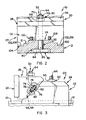
- reference numeral 10 generally indicates a vice according to the invention.
- the vice 10 includes an elongate base 12, and a first jaw 14 having a body portion 16 formed integrally with the base 12 and a clamping portion 17 defining a first clamping surface 18.
- a second jaw 20 is slidably displaceable along the base 12.
- the second jaw 20 comprises a body portion 24 and a clamping portion 26 which defines a second clamping surface 22 which is aligned with, and opposed to the first clamping surface 18.
- the body portion 24 of the second jaw 20 is displaceable with respect to the base 12 to vary the distance between the first clamping surface 18 and the second clamping surface 22.
- the vice 10 also includes a releasable locking means 30 for releasably locking the second jaw 20 to the base 12 at a selected distance from the first jaw 14 so as to inhibit displacement of the second jaw 20 with respect to the first jaw 14; and a displacement means 32 for displacing the second clamping surface 22 of the second jaw 20 in a direction towards the base 12 when it is locked to the base 12.
- the first jaw 14 comprises two separable parts, ie. a clamping portion 17 which defines the first clamping surface 18 and a body portion 16 formed integrally with the base 12.
- the clamping portion 17 has a locating projection 36 which is received in a locating socket 38 in the body portion 16.
- the body portion 16 defines a bore 40 co-axial with the socket 38, and a screw 42 which extends from the bore 40 into the locating projection 36 of the clamping portion 17, secures the clamping portion 17 and the body portion 16 together.
- the body portion 16 further defines a bore 44 at right angles to the socket 38, which extends from the socket 38 towards the base 12.
- a biassing means in the form of a helical spring 46 is located in the bore 44 and its ends abut a biassing surface 48 of the body portion 16 and a side wall 50 of the clamping portion 17 respectively, to bias the clamping portion 17 away from the base 12.
- the extent to which the clamping portion 17 can be displaced towards or away from the base 12 is limited and is dependent upon the width of the locating socket 38.
- An access passage 52 for an urging member in the form of a screw 54 is provided through the body portion 16 in communication with the socket 38 and the exterior respectively, and substantially co-axial with the bore 44.
- the access passage 52 is internally screw-threaded and the screw 54 is receivable in the passage 52 and is linearly displaceable towards and away from the base 12 to urge the clamping portion 17 towards the base 12 and to release it respectively.
- the clamping portion 26 of the second jaw 20 is reciprocally displaceable with respect to the body portion 24-towards and away from the base 12 and the first jaw 14.
- the body portion 24 and the clamping portion 26 are held in register with each other by means of the displacement means 32.
- the displacement means 32 comprises an elongate bolt-like element 56 having a shank 58, a portion 60 of which is fast with the body portion 24.
- the shank 58 extends through a bore 62 of the clamping portion 26.
- the free end portion 64 of the element 56 projects upwardly from the top of the clamping portion 26 and this portion 64 has an external screw-thread.
- the clamping portion 26 and the body portion 24 have substantially planar inclined surfaces 66 and 68 respectively which define an inclined plane along which the clamping portion 26 can slide relative to the body portion 24, the inclined surfaces 66, 68 extending from the base 12 in a direction away from the first jaw 14.
- the displacing means 32 also comprises an internally screw-threaded displacing nut 70 locatable on the end portion 64 of the element 56. The nut 70 is manually displaceable downwardly along the element 56 to displace the clamping portion 26 and hence the mating surface 66 downwardly with respect to the body portion 24 and the surface 68.
- the second jaw 20 includes an urging means for biassing the clamping portion 26 upwardly with respect to the body portion 24 ie. in a direction away from the base 12 and the first jaw 14.
- the urging means comprises a pair of transversely spaced helical springs 72 (only one of which is shown in Figure 3, the other spring being aligned therewith).
- the surfaces 66 and 68 define a pair of transversely spaced recesses 74 and 76 respectively.
- the recesses 74, 76 of the surface 66 will be aligned with the recesses 76 of the surface 68 to define a pair of transversely spaced cavities in the second jaw 20 to accommodate the springs 72.
- Each of the end walls of the cavities provide biassing walls 78 and 80 of the clamping portion 26 and the body portion 24 respectively.
- the springs 72 When the clamping portion 26 is displaced downwardly by tightening the displacing nut 70 on the element 56, the springs 72 are compressed as the recesses 74, 76 become misaligned. Accordingly when the nut 70 is loosened, the springs 72 urge the clamping portion 26 upwardly, away from the base 12 to re-align the recesses 74, 76.
- the body portion 24 is connected, in use, to the base 17 via the locking means 30 which comprises a connecting member in the form of a bolt 82.
- a head 84 of the bolt 82 provides a base part of substantially square section, and a shank 86 of the bolt extends through a bore 88 in the body portion 24.
- the bore 88 is disposed at right angles to the longitudinal axis of the base 12.
- the base 12 of the vice 10 has a longitudinally extending channel 90 running transversely to the clamping surface 18 of the first jaw 14.
- the bolt head 84 is held captive in the channel 90 and is slidable along it, and the shank 86 projects upwardly therefrom through an access slot 92 in the base 12 of the vice 10.
- the free end portion 94 of the shank 86 projects from an upper surface of the body portion 24 and is externally screw-threaded.
- a screw-threaded lock nut 96 is receivable on and displaceable along the shank 86 to lock the body portion 24 to the base 12.
- the upper surface of the base 12 along which the second jaw 20 is displaceable is stepped as can be seen in Figure 2.
- the two outermost longitudinally extending steps define bearing surfaces 100 having transverse saw-tooth formations 102 or alternative displacement inhibiting formations which are provided in the form of longitudinally extending strips.
- the under surface of the body portion 24 which engages the base 12 in use is stepped in a complementary fashion to the upper surface of the base 12, as can be seen in Figure 2.
- a portion of the two outermost longitudinally extending steps define bearing surfaces 104 having transverse saw-tooth formations 106 or alternative displacement inhibiting formations complementary to those of the bearing surfaces 100 of the base 12.
- the second jaw 20 includes an urging means in the form of a pair of transversely spaced leaf springs 108 for urging the body portion 24 away from the base 12.
- Recesses 110 in a rear wall 112 of the body portion 24 accommodate the springs 108, and the respective upper surfaces 114 of the recesses 110 provide biassing surfaces for the springs 108, while the uppermost portion 116 of the engaging surface of the base 12 provides an opposed biassing surface therefor.
- the clamping portion 17 of the first jaw 14 is secured to the body portion 16 of the jaw 14 and is urged away from the base 12 by the spring 46.
- the clamping portion 26 of the second jaw 20 is in an inoperative position in which it is clear of the base 12, as shown in Figure 3.
- the recesses 74 and 76 are aligned with each other, and the springs 72 are in a relatively uncompressed condition.
- the lock nut 96 is in its loosened configuration so that the second jaw 20 is slidably displaceable with respect to the base 12 towards and away from the first jaw 14.
- a selected workpiece (not shown) is placed against the clamping surface 18 of the first jaw 14 and second jaw 20 and is lightly clamped between the first and second clamping surfaces 18, 22 by sliding the second jaw 20 along the base towards the first jaw 14.
- the second jaw 20 is then locked in this position by tightening the nut 96.
- the clamping portion 17 of the first jaw 14 is urged towards the base 12 by tightening the screw 54 onto the projection 36 of the clamping portion 17 of the first jaw 14.
- the second clamping surface 22 is urged towards the first jaw 14 and the base 12 by tightening the displacing nut 70 and thereby displacing the clamping portion 26 of the second jaw 20 downwardly with respect to the body portion 24.
- the displacing nut 70 is loosened sufficiently to permit the springs 72 to urge the clamping portion 26 upwardly with respect to the body portion 24 and away from the base 12 and the first jaw 14.
- the lock nut 96 is loosened and the springs 108 urge the saw-tooth formations 106 of the body portion 24 out of engagement with the saw-tooth formations 102 of the base 12 to permit the second jaw 20 to be displaced with respect to the base 12 away from the first jaw 14.
- the screw 54 of the clamping portion 17 of the first jaw 14 is released and the spring 46 urges the clamping portion 17 away from the base 12.
- the displacement means 32 serves to displace the clamping portion 26 relative to the body portion 24 of the second jaw 20, as well as to guide the second jaw 20 along the channel 19 in the base 12 of the vice 10. Further, the displacement means 32 serves to urge the saw-tooth formations 106 of the body portion 24 into engagement with the strips of saw-tooth formations 102 on the base 12.
- the nut 70 bears against a washer 120 which in turn bears against an upper surface of the clamping portion 26 of the second jaw 20. When the nut 70 is tightened to urge the clamping portion 26 towards the base 12, the nut acts against the pair of transversely spaced helical springs 72.
- the mating planar surfaces 66, 68 are formed by a planar portion of a dovetailed joint 124 ( Figure 5) between the clamping portion 26 and the body portion 24 of the second jaw 20.
- the dovetail portion 126 which is formed integrally with the clamping portion 24 of the second jaw 20 fits in a suitably shaped recess in the body portion 24.
- the dovetail 126 fits with clearance in the recess of the body portion 24 to leave a space between a side portion of the recess and a side of the dovetail 126. This space defines a keyway in which a suitably shaped key 128 is inserted to lock the clamping portion 26 against lateral displacement relative to the body portion 24 of the second jaw 20.
- the saw-tooth formations 106 of the body portions are provided as replaceable inserts 130.
- the inserts 130 are bolted to the body portion by means of bolts 132.
- the strips of saw-tooth formations 102 which are provided on the base 12 are provided as removable inserts 134.
- the inserts 134 are secured to the base by means of bolts 136.
- the saw-tooth formations 102 and 106 become worn.
- the saw-tooth formations 102 of the base 12 are angled relative to the horizontal so that any debris such as metal filings can easily be removed from between the teeth of the formations 102 eg. by being washed with water which is used to cool a workpiece on which a metal working operation is being perfonned.
- the saw-tooth formations 106 of the body portion 24 are correspondingly angled.
- the pitch of the teeth of the formations 102 and 106 is about 6mn, and the clamping portion 26 of the second jaw 20 can be displaced about 10mm parallel to the base 12. Hence, a wide range of adjustment can be achieved between the clamping surfaces 18 and 22 of the vice 10.
- the bolt-like element 56 has a head 138 which is held captive in the channel 90 in the base 12.
- the shank 58 extends through the slot 92 in the base, through a bore 140 in the body portion 24 and an aligned bore 142 in the clamping portion 26.
- the bolt-like element 56 serves to guide the second jaw 20 along the base by means of the shank 58 of the element 56 being guided in the slot 92.
- the clamping portion 17 of the first jaw 14 is adjustable both normal to and parallel with the base 12 by means of an adjustment means.
- the adjustment means comprises a pair of transversely spaced Allen bolts 144.
- the bolts 144 extend through screw-threaded bores 146 in the body portion 16 of the first jaw 14 into threaded sockets 148 in the clamping portion 17 of the first jaw 14.
- a coil spring 150 is arranged co-axially with each of the bolts 144.
- the adjustment means further includes a screw-threaded stud 152 which projects from an upper surface of the body portion 16 of the first jaw 14.
- the stud 152 is screw-threadedly received in a threaded socket 154 in the body portion 16 of the first jaw 14.
- a nut 156 is provided on that portion of the stud 152 projecting from the body portion 16. The nut 156 bears against a washer 158 against a bearing surface 160 of the clamping portion 17 of the first jaw 14.
- a workpiece can be more rapidly and securely gripped than with other vices of which the Applicant is aware.
Landscapes
- Engineering & Computer Science (AREA)
- Mechanical Engineering (AREA)
- Gripping Jigs, Holding Jigs, And Positioning Jigs (AREA)
- Non-Silver Salt Photosensitive Materials And Non-Silver Salt Photography (AREA)
- Crystals, And After-Treatments Of Crystals (AREA)
- Saccharide Compounds (AREA)
- Materials For Medical Uses (AREA)
- Devices For Conveying Motion By Means Of Endless Flexible Members (AREA)
- Dowels (AREA)
- Jigs For Machine Tools (AREA)
- Glass Compositions (AREA)
Priority Applications (1)
| Application Number | Priority Date | Filing Date | Title |
|---|---|---|---|
| AT87300300T ATE66848T1 (de) | 1986-01-16 | 1987-01-14 | Schraubstock. |
Applications Claiming Priority (2)
| Application Number | Priority Date | Filing Date | Title |
|---|---|---|---|
| ZA86334 | 1986-01-16 | ||
| ZA860334 | 1986-01-16 |
Publications (3)
| Publication Number | Publication Date |
|---|---|
| EP0229717A2 true EP0229717A2 (de) | 1987-07-22 |
| EP0229717A3 EP0229717A3 (en) | 1987-10-14 |
| EP0229717B1 EP0229717B1 (de) | 1991-09-04 |
Family
ID=25578241
Family Applications (1)
| Application Number | Title | Priority Date | Filing Date |
|---|---|---|---|
| EP87300300A Expired - Lifetime EP0229717B1 (de) | 1986-01-16 | 1987-01-14 | Schraubstock |
Country Status (9)
| Country | Link |
|---|---|
| US (1) | US4736935A (de) |
| EP (1) | EP0229717B1 (de) |
| JP (1) | JPS62199367A (de) |
| AT (1) | ATE66848T1 (de) |
| AU (1) | AU587317B2 (de) |
| BR (1) | BR8700179A (de) |
| DE (1) | DE3772579D1 (de) |
| ES (1) | ES2025149B3 (de) |
| ZA (1) | ZA87214B (de) |
Cited By (2)
| Publication number | Priority date | Publication date | Assignee | Title |
|---|---|---|---|---|
| FR2664841A1 (fr) * | 1990-06-19 | 1992-01-24 | Mituo Izumi | Etau de machine. |
| WO2000067952A1 (de) * | 1999-05-06 | 2000-11-16 | Triag Ag | Schnellstverstellbares mehrfachspannsystem |
Families Citing this family (20)
| Publication number | Priority date | Publication date | Assignee | Title |
|---|---|---|---|---|
| US5150888A (en) * | 1986-12-15 | 1992-09-29 | Susan M. Durfee | Clamping mechanism in a vise jaw accessory system for attaching and releasing vise accessories while maintaining positional accuracy of the accessories |
| US5031887A (en) * | 1990-07-23 | 1991-07-16 | Lars Johanson | Locking system for precision vise |
| SE470338B (sv) * | 1992-06-09 | 1994-01-24 | Cue Dee Produkter Ab | Klämback för en vid ett profilelement anbringbar klämanordning |
| US5324013A (en) * | 1993-01-05 | 1994-06-28 | Marino Michael L | Clamping mechanism |
| JPH0717464U (ja) * | 1993-09-08 | 1995-03-28 | 株式会社武田機械 | バイスにおける可動挾持体の固定位置変更装置 |
| US5417409A (en) * | 1994-04-06 | 1995-05-23 | Reddell; Glen R. | Vise with sliding back jaw |
| WO1996033048A1 (en) * | 1995-04-21 | 1996-10-24 | Kurt Manufacturing Company, Inc. | Workholding wedge clamp |
| SE510538C2 (sv) * | 1997-09-09 | 1999-05-31 | Cue Dee Produkter Ab | Klämback |
| US6017026A (en) * | 1997-12-11 | 2000-01-25 | Durfee, Jr.; David L. | Machining vise |
| US6244580B1 (en) | 1998-10-14 | 2001-06-12 | Parlec, Inc. | Machining vise |
| DE112007001871T5 (de) * | 2006-08-10 | 2009-06-18 | Pascal Engineering Corp., Itami | Spannvorrichtung |
| GB0723406D0 (en) * | 2007-11-29 | 2008-01-09 | Prosurgics Ltd | A clamp |
| TWI409141B (zh) * | 2012-07-20 | 2013-09-21 | Lin Tseh Pei | 虎鉗活動顎快拆裝置 |
| US10357859B1 (en) * | 2014-03-06 | 2019-07-23 | Daniel J Reed | Clamping system for securing a work piece to a fixture |
| US9844855B1 (en) * | 2016-06-21 | 2017-12-19 | Po-Shen Chen | Workpiece clamp device with single side |
| US9895792B2 (en) * | 2016-06-21 | 2018-02-20 | Ju-Tan Chen | Workpiece clamp device capable for changing clamp angle |
| CN106514330A (zh) * | 2016-10-28 | 2017-03-22 | 广东长盈精密技术有限公司 | 一种压紧装置及使用该压紧装置的夹具 |
| RU198168U1 (ru) * | 2020-02-11 | 2020-06-22 | Акционерное общество "Научно-исследовательский институт Приборостроения имени В.В. Тихомирова" | Зажимное приспособление |
| TWI804374B (zh) * | 2022-07-04 | 2023-06-01 | 固地威企業股份有限公司 | 免用工具即能快速更換夾顎的精密虎鉗 |
| DE102024105648A1 (de) * | 2024-01-22 | 2025-07-24 | Fireball Tool Works Llc | Blockanordnungen mit einstellbarer Länge |
Family Cites Families (33)
| Publication number | Priority date | Publication date | Assignee | Title |
|---|---|---|---|---|
| US2511843A (en) * | 1950-06-20 | Screw-actuated vise jaw quickly | ||
| US381890A (en) * | 1888-04-24 | Machine vise | ||
| FR958039A (de) * | 1950-03-02 | |||
| US540413A (en) * | 1895-06-04 | Abraham vanderbeek | ||
| GB190301693A (en) * | 1903-01-23 | 1903-11-26 | Percy Blewett | Improvements in or relating to Bench Vices and the like. |
| US1405306A (en) * | 1920-08-09 | 1922-01-31 | Jose R Martin | Vise |
| US1751329A (en) * | 1927-08-31 | 1930-03-18 | Henry A Sawyer | Vise |
| US2552738A (en) * | 1947-08-01 | 1951-05-15 | Harold G Renner | Quick action precision vise |
| GB636520A (en) * | 1948-08-25 | 1950-05-03 | Walter Haas | Improvements in or relating to locking or clamping devices |
| US2584062A (en) * | 1949-04-22 | 1952-01-29 | Glacier Co Ltd | Machine vise having jaws movable downwardly when pressed against workpiece |
| GB676052A (en) * | 1949-07-09 | 1952-07-23 | Henry Folke Swenson | Improvements in or relating to a clamp for fixing the position of a workpiece on a supporting surface |
| DE831223C (de) * | 1950-06-17 | 1952-02-11 | Diezel & Panne G M B H | Schraubstock |
| US2667799A (en) * | 1952-10-09 | 1954-02-02 | Stanley J Rzepela | Machine vise having base-clamping screw and nut assembly for sectional movable jaws |
| US2861492A (en) * | 1955-09-08 | 1958-11-25 | Alfred P Hokanson | Vise-jaw face plate slidable and pivotable on backwardly sloping jaw surface |
| CH349937A (de) * | 1957-01-29 | 1960-10-31 | Ernest H Fischer S Soehne Ag | Einspannvorrichtung für Werkstücke, insbesondere Schraubstock |
| DE1121559B (de) * | 1957-01-29 | 1962-01-04 | Ernest H Fischer S Soehne Ag | Einspannvorrichtung, insbesondere Maschinenschraubstock |
| DE1155070B (de) * | 1957-04-06 | 1963-09-26 | Hermann Rueckle K G Werkzeugfa | Einspannvorrichtung, insbesondere Schraubstock |
| US2992665A (en) * | 1959-06-08 | 1961-07-18 | Mertz David | Vise |
| DE1135271B (de) * | 1959-10-20 | 1962-08-23 | Wilhelm Hammer | Einrichtung zum Verankern von auf der Aufspannflaeche eines Werkzeugmaschinentischesangeordneten Spannstoecken |
| DE1181647B (de) * | 1960-02-13 | 1964-11-12 | Hilma G M B H Maschf | Niederziehbacke fuer Schraubstoecke od. dgl. |
| FR1443185A (fr) * | 1965-04-07 | 1966-06-24 | Perfectionnements aux étaux pour machines-outils et applications analogues | |
| US3565417A (en) * | 1967-08-22 | 1971-02-23 | Georg Kesel Kg Werkzeugmaschin | Holddown jaw for vises |
| DE1807060A1 (de) * | 1967-11-15 | 1969-06-12 | Emato Ag | Niederzugbacke,insbesondere fuer Schraubstoecke |
| FR2003326A1 (de) * | 1968-03-06 | 1969-11-07 | Ogino Mitsuzo | |
| FR1593027A (de) * | 1968-09-25 | 1970-05-25 | ||
| US3682467A (en) * | 1970-07-23 | 1972-08-08 | Casper W Heinrich | Miter clamp |
| DE2044065A1 (de) * | 1970-09-05 | 1972-03-23 | Maschinenfabrik Hüma GmbH, 5912 Hilchenbach | Zweiteilige Niederziehbacke fur Schraubstocke oder dergleichen |
| DE2318147A1 (de) * | 1973-04-11 | 1974-10-31 | Prewo Werkzeug Masch | Niederzug-werkstueckspannvorrichtung |
| DE2323054C3 (de) * | 1973-05-08 | 1975-10-30 | Jakob 5000 Koeln Wollenhaupt | Vorrichtung zum Befestigen von Nutenplatten od. dgl. zur Aufnahme von Steuernocken an Werkzeugmaschinen bzw. an Voreinstelleinrichtungen |
| DE2447243B2 (de) * | 1974-10-03 | 1976-11-25 | Prewo, Willi, 7126 Sersheim | Niederzug-werkstueckspannvorrichtung, insbesondere niederzug-maschinenschraubstock |
| DE3023322A1 (de) * | 1980-06-21 | 1982-01-14 | Kommanditgesellschaft Servotron-Tabert GmbH & Co, 2351 Trappenkamp | Niederzug-spannvorrichtung zum einspannen von zu bearbeitenden werkstuecken |
| DE3043606C2 (de) * | 1980-11-19 | 1983-05-26 | Gerhard 7990 Friedrichshafen Arnold | Spannvorrichtung, insbesondere Schraubstock |
| JPS58126140U (ja) * | 1982-02-19 | 1983-08-27 | 相生精機株式会社 | ネジ締付傾斜面倍力式クランプ |
-
1987
- 1987-01-13 ZA ZA87214A patent/ZA87214B/xx unknown
- 1987-01-13 US US07/002,724 patent/US4736935A/en not_active Expired - Fee Related
- 1987-01-14 DE DE8787300300T patent/DE3772579D1/de not_active Expired - Lifetime
- 1987-01-14 ES ES87300300T patent/ES2025149B3/es not_active Expired - Lifetime
- 1987-01-14 EP EP87300300A patent/EP0229717B1/de not_active Expired - Lifetime
- 1987-01-14 AT AT87300300T patent/ATE66848T1/de not_active IP Right Cessation
- 1987-01-16 BR BR8700179A patent/BR8700179A/pt not_active IP Right Cessation
- 1987-01-16 JP JP62006292A patent/JPS62199367A/ja active Pending
- 1987-03-25 AU AU70596/87A patent/AU587317B2/en not_active Ceased
Cited By (3)
| Publication number | Priority date | Publication date | Assignee | Title |
|---|---|---|---|---|
| FR2664841A1 (fr) * | 1990-06-19 | 1992-01-24 | Mituo Izumi | Etau de machine. |
| WO2000067952A1 (de) * | 1999-05-06 | 2000-11-16 | Triag Ag | Schnellstverstellbares mehrfachspannsystem |
| US6659439B1 (en) | 1999-05-06 | 2003-12-09 | Triag Ag | Quickly adjustable multiple clamping system |
Also Published As
| Publication number | Publication date |
|---|---|
| US4736935A (en) | 1988-04-12 |
| EP0229717A3 (en) | 1987-10-14 |
| EP0229717B1 (de) | 1991-09-04 |
| JPS62199367A (ja) | 1987-09-03 |
| ES2025149B3 (es) | 1992-03-16 |
| ZA87214B (en) | 1987-09-30 |
| DE3772579D1 (de) | 1991-10-10 |
| BR8700179A (pt) | 1987-12-08 |
| AU7059687A (en) | 1988-09-29 |
| ATE66848T1 (de) | 1991-09-15 |
| AU587317B2 (en) | 1989-08-10 |
Similar Documents
| Publication | Publication Date | Title |
|---|---|---|
| US4736935A (en) | Vice | |
| US5893551A (en) | Vise with fully machinable jaws | |
| US4706949A (en) | Vise jaw support system and interchangeable vise jaws therefor | |
| US4798371A (en) | Chucking device, in particular a vise | |
| DE817693T1 (de) | Schnellwechselfutter für sägeblätter | |
| DE68914276T2 (de) | Schnell einrastende zusatzeinheit für maschinen-schraubstöcke. | |
| DE102010047380B3 (de) | Linearer mechanischer Schnellverschluß | |
| JPH0811343B2 (ja) | 被加工部品の装着装置 | |
| EP2370221A1 (de) | Werkzeughalter zum festklemmen eines einsatzhalters | |
| US4185935A (en) | Coupling apparatus | |
| US20150336241A1 (en) | Soft jaw for a machine vise | |
| US5150888A (en) | Clamping mechanism in a vise jaw accessory system for attaching and releasing vise accessories while maintaining positional accuracy of the accessories | |
| JPH0624707B2 (ja) | バイス | |
| US4949946A (en) | Quick-acting clamping device | |
| PL117607B1 (en) | Cutting tool for machining metal workpieces | |
| US3186706A (en) | Vise construction | |
| US2748641A (en) | Holding means for the removable jaw of a slidable outer jaw wrench | |
| AU2002356110B2 (en) | Adjustable spanner | |
| US5031887A (en) | Locking system for precision vise | |
| US6698739B1 (en) | Apparatus for retaining objects on a surface and related methods | |
| US5374041A (en) | Vise | |
| GB2098891A (en) | Clamping work tables | |
| US20260061562A1 (en) | Snap-jaw vice assembly | |
| CN216883678U (zh) | 一种活扳手 | |
| JP4620733B2 (ja) | アダプタにカッターヘッドをクランプするためのシステム、カッターヘッド、および固定具 |
Legal Events
| Date | Code | Title | Description |
|---|---|---|---|
| PUAI | Public reference made under article 153(3) epc to a published international application that has entered the european phase |
Free format text: ORIGINAL CODE: 0009012 |
|
| AK | Designated contracting states |
Kind code of ref document: A2 Designated state(s): AT BE CH DE ES FR GB GR IT LI LU NL SE |
|
| PUAL | Search report despatched |
Free format text: ORIGINAL CODE: 0009013 |
|
| AK | Designated contracting states |
Kind code of ref document: A3 Designated state(s): AT BE CH DE ES FR GB GR IT LI LU NL SE |
|
| 17P | Request for examination filed |
Effective date: 19880219 |
|
| 17Q | First examination report despatched |
Effective date: 19881209 |
|
| GRAA | (expected) grant |
Free format text: ORIGINAL CODE: 0009210 |
|
| AK | Designated contracting states |
Kind code of ref document: B1 Designated state(s): AT BE CH DE ES FR GB GR IT LI LU NL SE |
|
| PG25 | Lapsed in a contracting state [announced via postgrant information from national office to epo] |
Ref country code: GR Free format text: LAPSE BECAUSE OF FAILURE TO SUBMIT A TRANSLATION OF THE DESCRIPTION OR TO PAY THE FEE WITHIN THE PRESCRIBED TIME-LIMIT Effective date: 19910904 |
|
| REF | Corresponds to: |
Ref document number: 66848 Country of ref document: AT Date of ref document: 19910915 Kind code of ref document: T |
|
| ITF | It: translation for a ep patent filed | ||
| REF | Corresponds to: |
Ref document number: 3772579 Country of ref document: DE Date of ref document: 19911010 |
|
| ET | Fr: translation filed | ||
| REG | Reference to a national code |
Ref country code: ES Ref legal event code: FG2A Ref document number: 2025149 Country of ref document: ES Kind code of ref document: B3 |
|
| PLBE | No opposition filed within time limit |
Free format text: ORIGINAL CODE: 0009261 |
|
| STAA | Information on the status of an ep patent application or granted ep patent |
Free format text: STATUS: NO OPPOSITION FILED WITHIN TIME LIMIT |
|
| 26N | No opposition filed | ||
| EPTA | Lu: last paid annual fee | ||
| PGFP | Annual fee paid to national office [announced via postgrant information from national office to epo] |
Ref country code: FR Payment date: 19931230 Year of fee payment: 8 |
|
| PGFP | Annual fee paid to national office [announced via postgrant information from national office to epo] |
Ref country code: GB Payment date: 19940105 Year of fee payment: 8 |
|
| PGFP | Annual fee paid to national office [announced via postgrant information from national office to epo] |
Ref country code: BE Payment date: 19940110 Year of fee payment: 8 |
|
| PGFP | Annual fee paid to national office [announced via postgrant information from national office to epo] |
Ref country code: DE Payment date: 19940117 Year of fee payment: 8 |
|
| PGFP | Annual fee paid to national office [announced via postgrant information from national office to epo] |
Ref country code: SE Payment date: 19940118 Year of fee payment: 8 |
|
| PGFP | Annual fee paid to national office [announced via postgrant information from national office to epo] |
Ref country code: AT Payment date: 19940121 Year of fee payment: 8 |
|
| PGFP | Annual fee paid to national office [announced via postgrant information from national office to epo] |
Ref country code: ES Payment date: 19940126 Year of fee payment: 8 |
|
| PGFP | Annual fee paid to national office [announced via postgrant information from national office to epo] |
Ref country code: CH Payment date: 19940128 Year of fee payment: 8 |
|
| PGFP | Annual fee paid to national office [announced via postgrant information from national office to epo] |
Ref country code: NL Payment date: 19940131 Year of fee payment: 8 Ref country code: LU Payment date: 19940131 Year of fee payment: 8 |
|
| PG25 | Lapsed in a contracting state [announced via postgrant information from national office to epo] |
Ref country code: LU Free format text: LAPSE BECAUSE OF NON-PAYMENT OF DUE FEES Effective date: 19950114 Ref country code: GB Effective date: 19950114 Ref country code: AT Effective date: 19950114 |
|
| PG25 | Lapsed in a contracting state [announced via postgrant information from national office to epo] |
Ref country code: SE Effective date: 19950115 |
|
| PG25 | Lapsed in a contracting state [announced via postgrant information from national office to epo] |
Ref country code: ES Free format text: LAPSE BECAUSE OF NON-PAYMENT OF DUE FEES Effective date: 19950116 |
|
| EAL | Se: european patent in force in sweden |
Ref document number: 87300300.8 |
|
| PG25 | Lapsed in a contracting state [announced via postgrant information from national office to epo] |
Ref country code: LI Effective date: 19950131 Ref country code: CH Effective date: 19950131 Ref country code: BE Effective date: 19950131 |
|
| BERE | Be: lapsed |
Owner name: VASAPOLLI SANTO Effective date: 19950131 |
|
| PG25 | Lapsed in a contracting state [announced via postgrant information from national office to epo] |
Ref country code: NL Effective date: 19950801 |
|
| GBPC | Gb: european patent ceased through non-payment of renewal fee |
Effective date: 19950114 |
|
| PG25 | Lapsed in a contracting state [announced via postgrant information from national office to epo] |
Ref country code: FR Effective date: 19950929 |
|
| REG | Reference to a national code |
Ref country code: CH Ref legal event code: PL |
|
| NLV4 | Nl: lapsed or anulled due to non-payment of the annual fee |
Effective date: 19950801 |
|
| PG25 | Lapsed in a contracting state [announced via postgrant information from national office to epo] |
Ref country code: DE Effective date: 19951003 |
|
| EUG | Se: european patent has lapsed |
Ref document number: 87300300.8 |
|
| REG | Reference to a national code |
Ref country code: FR Ref legal event code: ST |
|
| REG | Reference to a national code |
Ref country code: ES Ref legal event code: FD2A Effective date: 19990301 |
|
| PG25 | Lapsed in a contracting state [announced via postgrant information from national office to epo] |
Ref country code: IT Free format text: LAPSE BECAUSE OF NON-PAYMENT OF DUE FEES;WARNING: LAPSES OF ITALIAN PATENTS WITH EFFECTIVE DATE BEFORE 2007 MAY HAVE OCCURRED AT ANY TIME BEFORE 2007. THE CORRECT EFFECTIVE DATE MAY BE DIFFERENT FROM THE ONE RECORDED. Effective date: 20050114 |