EP0229746B1 - Rückziehgerät für ein Kleinklavier und Mittel zu seiner Anwendung - Google Patents
Rückziehgerät für ein Kleinklavier und Mittel zu seiner Anwendung Download PDFInfo
- Publication number
- EP0229746B1 EP0229746B1 EP87810035A EP87810035A EP0229746B1 EP 0229746 B1 EP0229746 B1 EP 0229746B1 EP 87810035 A EP87810035 A EP 87810035A EP 87810035 A EP87810035 A EP 87810035A EP 0229746 B1 EP0229746 B1 EP 0229746B1
- Authority
- EP
- European Patent Office
- Prior art keywords
- rod
- push
- hammer
- tip
- jack
- Prior art date
- Legal status (The legal status is an assumption and is not a legal conclusion. Google has not performed a legal analysis and makes no representation as to the accuracy of the status listed.)
- Expired - Lifetime
Links
- 230000007246 mechanism Effects 0.000 title description 8
- 230000000994 depressogenic effect Effects 0.000 claims 1
- 239000000853 adhesive Substances 0.000 description 1
- 230000001070 adhesive effect Effects 0.000 description 1
- 238000013459 approach Methods 0.000 description 1
- 238000010276 construction Methods 0.000 description 1
- 230000002787 reinforcement Effects 0.000 description 1
- 230000000717 retained effect Effects 0.000 description 1
- 239000011435 rock Substances 0.000 description 1
- 238000004904 shortening Methods 0.000 description 1
- 230000006641 stabilisation Effects 0.000 description 1
- 238000011105 stabilization Methods 0.000 description 1
- 239000002023 wood Substances 0.000 description 1
Images
Classifications
-
- G—PHYSICS
- G10—MUSICAL INSTRUMENTS; ACOUSTICS
- G10C—PIANOS, HARPSICHORDS, SPINETS OR SIMILAR STRINGED MUSICAL INSTRUMENTS WITH ONE OR MORE KEYBOARDS
- G10C3/00—Details or accessories
- G10C3/16—Actions
- G10C3/161—Actions specially adapted for upright pianos
-
- G—PHYSICS
- G10—MUSICAL INSTRUMENTS; ACOUSTICS
- G10C—PIANOS, HARPSICHORDS, SPINETS OR SIMILAR STRINGED MUSICAL INSTRUMENTS WITH ONE OR MORE KEYBOARDS
- G10C3/00—Details or accessories
- G10C3/16—Actions
- G10C3/18—Hammers
-
- G—PHYSICS
- G10—MUSICAL INSTRUMENTS; ACOUSTICS
- G10C—PIANOS, HARPSICHORDS, SPINETS OR SIMILAR STRINGED MUSICAL INSTRUMENTS WITH ONE OR MORE KEYBOARDS
- G10C9/00—Methods, tools or materials specially adapted for the manufacture or maintenance of musical instruments covered by this subclass
Definitions
- the upright piano has, compared to the grand piano, the disadvantage of not allowing, when the key is in the low position, after the hammer strikes the string, a new strike with a movement of small amplitude. This is particularly troublesome, for example, when it is necessary to perform trills, especially in "pianissimo".
- the grand piano on the contrary allows such successions of strikes even when the key is in the low position, with movements of very low amplitude.
- This advantage of the grand piano is due to its double escapement mechanism. Simpler, the mechanism of the upright piano has only one exhaust.
- Various unsuccessful attempts have been made to obtain from the upright piano a result analogous to that achieved with the grand piano.
- the present inventions aim to provide an exhaust device for upright piano, as well as means for implementing such a device, which allows successive strikes fast rope with very small amplitude movements, when the key is in the low position.
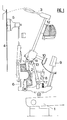
- Figure 1 is a side view of a conventional upright piano mechanism, the key being in the high position, that is to say at rest.
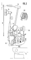
- Figure 2 is a view of the same mechanism, with the key in the down position, that is to say pressed, the hammer returning back after striking the rope.
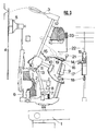
- Figure 3 is a side view of a device according to the invention, in a first variant, the key being in the high position.
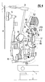
- FIG. 4 is a side view of a device according to the invention, in a second variant, the key being pressed and the hammer launched towards the rope or in its backward stroke after striking the rope; the dotted lines represent the position of certain parts when the key is in the high position and in an intermediate position.
- German Patent No. 123,696 has proposed a device in which the conventional pusher is doubled by a second pusher.
- This second pusher is fixed to the catcher by a flexible rod. After striking the rope, and if the key remains pressed, the hammer goes back and abuts against this second pusher. When the key is raised to mid-height, the pusher can again slide under the nut because the hammer is retained by the second pusher. The device is thus recharged as soon as the button is halfway up. In this way, it is possible, by movements of a relatively small amplitude, to restart the hammer towards the rope.
- the present invention aims to provide a device which allows rapid repetition of the same note without the need to let the key rise to halfway up, and which avoids the risk of untimely rebounding of the hammer up to the rope.
- the device which is the subject of the invention comprises, in addition to a first pusher 2, a second exhaust pusher 14.
- This second pusher is fixed, directly or by means of other parts, to the catcher.
- the second plunger extends towards the hammer handle and its tip 15 is provided with a felt roller.
- the distance between the end 15 of the second pusher and the handle of the hammer is calculated so that the handle comes to bear against this end at about the moment when the counter-catch 10 comes to rest on the catch 9.
- the second exhaust pusher 14 can act on the handle of the hammer when the button is pressed again.
- the second pusher In order for the second pusher to fulfill its role as a true exhaust pusher, it should be allowed to tilt so that its end leaves contact with the hammer handle at the end of the stroke, in the same way as the first pusher leaves at the end of run its fulcrum under the nut to let the hammer finish its run with its only momentum.
- the second pusher is mounted on a pin 16 which is itself fixed on the catcher.
- the axis 16 is a part of a rod 17 which allows attachment to the catcher by means of a clamping piece 18. Another part of the same rod, parallel to the axis 16 forms a stop 19 against which the body of the second pusher abuts.
- a stop cushion 20 absorbs contact with the stop 19.
- the height of this stop is adjustable by simply twisting the rod 17.
- the height of the stop determines the height at which the tip 15 which meets the handle of the hammer stops.
- the angle formed from the right connecting the axis 16 and the tip 15, on the one hand, and the axis of the hammer handle, on the other hand, is approximately straight at the moment when the cushion d stop 20 rests on stop 19.
- the second pusher has a tip 21. This tip 21, like the tip 15, is provided with 'a felt wheel which softens the contact.
- a trigger stop 22 is fixed on a non-movable part of the piano, on the path that the tip 21 must travel.
- the stop is placed at an adjustable height. This height is calculated so that the end 21 of the second pusher comes to apply at the end of the race on this stop and slides against it.
- the end 21 remains at the height determined by the stop, while the axis 16 continues to rise with the catcher, the second pusher rocks around the axis 16 and the end 15 rises, leaving the handle hammer.
- the second pusher leaves contact with the handle of the hammer at the end of the stroke. It is enough to slightly release the key so that the second pusher descends, under the action of a spring 24, and is again ready to push back the handle of the hammer, even before the first pusher has returned under the nut. It suffices that the second pusher moves back by the small distance X for the tip 15 to descend again by traversing the distance Y.
- the length of the second plunger is adjustable: to shorten it, it suffices to push the rod, preferably metallic, which forms the arm which extends in the direction of the hammer handle, into the body of the plunger, which is preferably in wood; traction, on the contrary, causes elongation. It is also possible to fix on the handle of the hammer one or more pieces at the height where the tip 15 of the pusher meets the handle. This is also a way of shortening the distance between the tip 15 of the hammer handle.
- the stop 22 is a bent rod which is fixed to the celestial bar. This rod is in the same vertical plane as the path of the second pusher. Its lower part, which comes into contact with the tip 21 when the latter is at the end of its travel, is approximately horizontal.
- the bent rod is preferably inserted into a wooden bar 23.
- This bar preferably extends over the entire length of the piano and carries all of the angled trigger rods.
- the fixing of the bar 23 to the celestial bar is done simply by means of an adhesive strip.
- the height of the angled trigger rod 22 is adjusted by pulling it or pushing it down or up, that is to say by pushing it more or less deeply into the bar 23.
- the stop 22 is a button, similar to the exhaust button.
- This button is fixed by a screw in a bar 23.
- the arre 23 is no longer attached here to the celestial bar; it is at the center bar, for example via crosspieces which are not shown in the drawing.
- Such a construction makes it possible to remove the celestial bar without removing the bar 23, and thus to easily adjust the height of the buttons by means of the screws.
- the role of the celestial bar is reduced: on the one hand it is not used for fixing the trigger stop, and, on the other hand, it is no longer essential to serve as a fulcrum with a hammer when the main exhaust device is lifted, since the second exhaust pusher 14 is sufficient to fulfill this role.
- the celestial bar is therefore only a secondary support point and serves mainly as a support for the soft pedal and as a reinforcement and stabilization bar for the entire piano. It may be advantageous to make it thinner, to place it higher (in order to make easier access to the heads of the adjustment screws for the stops) and to fix it by means of a device which makes it easily removable, in view to facilitate adjustment.
- stops in the form of bent bars with a bar 23 which is not fixed to the celestial bar.
Landscapes
- Physics & Mathematics (AREA)
- Engineering & Computer Science (AREA)
- Acoustics & Sound (AREA)
- Multimedia (AREA)
- Electrophonic Musical Instruments (AREA)
- Stringed Musical Instruments (AREA)
- Insulators (AREA)
- Organic Low-Molecular-Weight Compounds And Preparation Thereof (AREA)
- Component Parts Of Construction Machinery (AREA)
- Projection Apparatus (AREA)
- Massaging Devices (AREA)
Claims (6)
- Stoßzungenvorrichtungen für ein Pianino, mit einem ersten Stößel (2), dessen aufsteigende Bewegung den Hammer (3) gegen die Saite (4) treibt, und mit mindestens einem zweiten Stößel (14), der am Fänger (9) oder an einem mit dem Fänger verbundenen Teil befestigt ist und sich in Richtung des Hammerstiels erstreckt, wobei der Abstand zwischen der Spitze (15) des zweiten Stößels und dem Hammerstiel oder einem mit dem Hammerstiel verbundenen Teil so gewählt ist, daß sich der Hammerstiel auf seinem Rückweg, nachdem er die Saite getroffen hat, gegen besagte Spitze abstützt, wenn die Taste (1) noch vollständig oder teilweise gedrückt ist,
dadurch gekennzeichnet,
daß die Berührung zwischen dem Hammerstiel und der Spitze (15) des zweiten Stößels (14) stattfindet, wenn die Taste geringfügig freigegeben ist, daß der zweite Stößel (14) am Fänger (9) oder an einem mit dem Fänger verbundenen Teil mittels einer Achse (16) befestigt ist, die dem zweiten Stößel ein Schwenken um besagte Achse gestattet, und daß geeignete Mittel vorgesehen sind, um eine solche Schwenkbewegung zu erzeugen und somit die Spitze (15) des zweiten Stößels am Ende der absteigenden Bewegung der Taste (1) unter ihrer Bewegung fort vom Hammerstiel anzuheben. - Vorrichtung nach Anspruch 1, dadurch gekennzeichnet, daß die Mittel zum Anheben der Spitze (15) des zweiten Stößels aus einem Auslöseanschlag (22), der verstellbar an einem unbeweglichen Abschnitt des Pianos befestigt ist, und aus der anderen Spitze (21) des zweiten Stößels bestehen, wobei die andere Spitze und der Auslöseanschlag derart angepaßt sind, daß sich besagte andere Spitze wenigstens während der Endphase der aufsteigenden Bewegung des Fängers unter Verschwenken des zweiten Stößels an dem Auslöseanschlag abstützt.
- Vorrichtung nach Anspruch 1, dadurch gekennzeichnet, daß der zweite Stößel lösbar am Fänger oder an einem mit dem Fänger verbundenen Teil befestigt ist.
- Vorrichtung nach Anspruch 2, dadurch gekennzeichnet, daß der Auslöseanschlag (22) ein Knopf ist, der verstellbar mittels einer Schraube befestigt ist.
- Vorrichtung nach den Ansprüchen 3 und 4.
- Stößel (14) für eine Vorrichtung nach den Ansprüchen 1 bis 5, dadurch gekennzeichnet, daß seine beiden Spitzen (15, 21) mit Filzröllchen versehen sind.
Priority Applications (1)
| Application Number | Priority Date | Filing Date | Title |
|---|---|---|---|
| AT87810035T ATE89093T1 (de) | 1986-01-17 | 1987-01-19 | Rueckziehgeraet fuer ein kleinklavier und mittel zu seiner anwendung. |
Applications Claiming Priority (2)
| Application Number | Priority Date | Filing Date | Title |
|---|---|---|---|
| CH17586 | 1986-01-17 | ||
| CH175/86 | 1986-01-17 |
Publications (3)
| Publication Number | Publication Date |
|---|---|
| EP0229746A2 EP0229746A2 (de) | 1987-07-22 |
| EP0229746A3 EP0229746A3 (en) | 1989-03-08 |
| EP0229746B1 true EP0229746B1 (de) | 1993-05-05 |
Family
ID=4180973
Family Applications (1)
| Application Number | Title | Priority Date | Filing Date |
|---|---|---|---|
| EP87810035A Expired - Lifetime EP0229746B1 (de) | 1986-01-17 | 1987-01-19 | Rückziehgerät für ein Kleinklavier und Mittel zu seiner Anwendung |
Country Status (5)
| Country | Link |
|---|---|
| EP (1) | EP0229746B1 (de) |
| AT (1) | ATE89093T1 (de) |
| DE (2) | DE3785680T2 (de) |
| ES (1) | ES2014214A4 (de) |
| GR (1) | GR900300103T1 (de) |
Families Citing this family (4)
| Publication number | Priority date | Publication date | Assignee | Title |
|---|---|---|---|---|
| WO1993003477A1 (fr) * | 1991-08-01 | 1993-02-18 | Vladislav Vladimirovich Volkov | Mecanisme de touche pour piano |
| JPH0683326A (ja) * | 1992-08-31 | 1994-03-25 | Yamaha Corp | アップライトピアノのアクション |
| DE4414109A1 (de) * | 1994-04-22 | 1995-10-26 | Helmut Karl | Repetitierende Klaviermechanik |
| CN111531352A (zh) * | 2020-04-14 | 2020-08-14 | 陈忠 | 一种二胡琴筒旋转式压条装置 |
Family Cites Families (3)
| Publication number | Priority date | Publication date | Assignee | Title |
|---|---|---|---|---|
| DE123696C (de) * | ||||
| DE51541C (de) * | H. L. HONE in Lexington, Kentucky | Repititions-Mechanik für Pianofortes | ||
| US1599743A (en) * | 1923-10-01 | 1926-09-14 | Carnes John Wilson | Piano action |
-
1987
- 1987-01-19 DE DE87810035T patent/DE3785680T2/de not_active Expired - Fee Related
- 1987-01-19 ES ES87810035T patent/ES2014214A4/es active Pending
- 1987-01-19 DE DE198787810035T patent/DE229746T1/de active Pending
- 1987-01-19 AT AT87810035T patent/ATE89093T1/de active
- 1987-01-19 EP EP87810035A patent/EP0229746B1/de not_active Expired - Lifetime
-
1991
- 1991-09-27 GR GR90300103T patent/GR900300103T1/el unknown
Also Published As
| Publication number | Publication date |
|---|---|
| ATE89093T1 (de) | 1993-05-15 |
| GR900300103T1 (en) | 1991-09-27 |
| EP0229746A3 (en) | 1989-03-08 |
| ES2014214A4 (es) | 1990-07-01 |
| DE3785680D1 (de) | 1993-06-09 |
| EP0229746A2 (de) | 1987-07-22 |
| DE229746T1 (de) | 1990-09-06 |
| DE3785680T2 (de) | 1993-11-11 |
Similar Documents
| Publication | Publication Date | Title |
|---|---|---|
| EP0384837B1 (de) | Pianodämpfermechanik | |
| EP1131139B1 (de) | Sicherheitsskibindung | |
| DK166471B1 (da) | Anslagsmekanisme | |
| EP0807303B1 (de) | Kombiniertes pedal für musikinstrumente wie pianos | |
| EP0284558B1 (de) | Auslösungsmechanik für Klaviere | |
| CN101019169B (zh) | 立式钢琴的复奏机构 | |
| EP0229746A2 (de) | Rückziehgerät für ein Kleinklavier und Mittel zu seiner Anwendung | |
| FR2643608A1 (de) | ||
| JP2011203474A (ja) | アップライトピアノ型アクション | |
| FR2499863A1 (fr) | Talonniere pour fixation de ski de securite | |
| FR2652186A1 (fr) | Pianos droits a mecanique perfectionnee. | |
| FR2846455A1 (fr) | Dispositif apte et destine a faciliter le rechargement d'une mecanique de piano droit | |
| CH714634A1 (fr) | Levier flexible de répétition pour dispositif d'échappement d'un piano droit. | |
| LU88093A1 (fr) | Mecanique de piano droit du type a echappement | |
| FR2679688A1 (fr) | Dispositif de repetition positive pour mecaniques de pianos droits. | |
| BE475552A (de) | ||
| US6130372A (en) | Striking mechanism for a string instrument | |
| EP0245121B1 (de) | Entweichungsmechanik für ein Klavier | |
| FR2590061A1 (fr) | Mecanisme d'echappement destine a un piano droit | |
| BE351550A (de) | ||
| BE507414A (de) | ||
| JPH07160251A (ja) | 竪型ピアノのアクション装置 | |
| CH137345A (fr) | Machine vendeuse à déclanchement monétaire. | |
| CH279653A (fr) | Jeu de quilles. | |
| FR2843226A1 (fr) | Pedale pour instrument a percussion |
Legal Events
| Date | Code | Title | Description |
|---|---|---|---|
| PUAI | Public reference made under article 153(3) epc to a published international application that has entered the european phase |
Free format text: ORIGINAL CODE: 0009012 |
|
| 17P | Request for examination filed |
Effective date: 19870119 |
|
| AK | Designated contracting states |
Kind code of ref document: A2 Designated state(s): AT BE CH DE ES FR GB GR IT LI LU NL SE |
|
| PUAL | Search report despatched |
Free format text: ORIGINAL CODE: 0009013 |
|
| AK | Designated contracting states |
Kind code of ref document: A3 Designated state(s): AT BE CH DE ES FR GB GR IT LI LU NL SE |
|
| ITCL | It: translation for ep claims filed |
Representative=s name: STUDIO MASSARI S.R.L. |
|
| TCNL | Nl: translation of patent claims filed | ||
| GBC | Gb: translation of claims filed (gb section 78(7)/1977) | ||
| TCAT | At: translation of patent claims filed | ||
| DET | De: translation of patent claims | ||
| 17Q | First examination report despatched |
Effective date: 19910404 |
|
| GRAA | (expected) grant |
Free format text: ORIGINAL CODE: 0009210 |
|
| AK | Designated contracting states |
Kind code of ref document: B1 Designated state(s): AT BE CH DE ES FR GB GR IT LI LU NL SE |
|
| PG25 | Lapsed in a contracting state [announced via postgrant information from national office to epo] |
Ref country code: GB Effective date: 19930505 Ref country code: IT Free format text: LAPSE BECAUSE OF FAILURE TO SUBMIT A TRANSLATION OF THE DESCRIPTION OR TO PAY THE FEE WITHIN THE PRE;WARNING: LAPSES OF ITALIAN PATENTS WITH EFFECTIVE DATE BEFORE 2007 MAY HAVE OCCURRED AT ANY TIME BEFORE 2007. THE CORRECT EFFECTIVE DATE MAY BE DIFFERENT FROM THE ONE RECORDED.SCRIBED TIME-LIMIT Effective date: 19930505 Ref country code: GR Free format text: LAPSE BECAUSE OF FAILURE TO SUBMIT A TRANSLATION OF THE DESCRIPTION OR TO PAY THE FEE WITHIN THE PRESCRIBED TIME-LIMIT Effective date: 19930505 Ref country code: SE Effective date: 19930505 Ref country code: NL Effective date: 19930505 |
|
| REF | Corresponds to: |
Ref document number: 89093 Country of ref document: AT Date of ref document: 19930515 Kind code of ref document: T |
|
| REF | Corresponds to: |
Ref document number: 3785680 Country of ref document: DE Date of ref document: 19930609 |
|
| NLV1 | Nl: lapsed or annulled due to failure to fulfill the requirements of art. 29p and 29m of the patents act | ||
| GBV | Gb: ep patent (uk) treated as always having been void in accordance with gb section 77(7)/1977 [no translation filed] |
Effective date: 19930505 |
|
| PG25 | Lapsed in a contracting state [announced via postgrant information from national office to epo] |
Ref country code: ES Free format text: LAPSE BECAUSE OF NON-PAYMENT OF DUE FEES Effective date: 19940120 |
|
| PG25 | Lapsed in a contracting state [announced via postgrant information from national office to epo] |
Ref country code: LU Free format text: LAPSE BECAUSE OF NON-PAYMENT OF DUE FEES Effective date: 19940131 Ref country code: BE Effective date: 19940131 |
|
| PLBE | No opposition filed within time limit |
Free format text: ORIGINAL CODE: 0009261 |
|
| STAA | Information on the status of an ep patent application or granted ep patent |
Free format text: STATUS: NO OPPOSITION FILED WITHIN TIME LIMIT |
|
| 26N | No opposition filed | ||
| BERE | Be: lapsed |
Owner name: KUMMER FERNAND Effective date: 19940131 |
|
| PGFP | Annual fee paid to national office [announced via postgrant information from national office to epo] |
Ref country code: FR Payment date: 19961024 Year of fee payment: 11 |
|
| PGFP | Annual fee paid to national office [announced via postgrant information from national office to epo] |
Ref country code: CH Payment date: 19961206 Year of fee payment: 11 |
|
| PGFP | Annual fee paid to national office [announced via postgrant information from national office to epo] |
Ref country code: DE Payment date: 19970118 Year of fee payment: 11 |
|
| PGFP | Annual fee paid to national office [announced via postgrant information from national office to epo] |
Ref country code: AT Payment date: 19970424 Year of fee payment: 11 |
|
| PG25 | Lapsed in a contracting state [announced via postgrant information from national office to epo] |
Ref country code: AT Free format text: LAPSE BECAUSE OF NON-PAYMENT OF DUE FEES Effective date: 19980119 |
|
| PG25 | Lapsed in a contracting state [announced via postgrant information from national office to epo] |
Ref country code: FR Free format text: THE PATENT HAS BEEN ANNULLED BY A DECISION OF A NATIONAL AUTHORITY Effective date: 19980131 Ref country code: LI Free format text: LAPSE BECAUSE OF NON-PAYMENT OF DUE FEES Effective date: 19980131 Ref country code: CH Free format text: LAPSE BECAUSE OF NON-PAYMENT OF DUE FEES Effective date: 19980131 |
|
| REG | Reference to a national code |
Ref country code: CH Ref legal event code: PL |
|
| PG25 | Lapsed in a contracting state [announced via postgrant information from national office to epo] |
Ref country code: DE Free format text: LAPSE BECAUSE OF NON-PAYMENT OF DUE FEES Effective date: 19981001 |
|
| REG | Reference to a national code |
Ref country code: FR Ref legal event code: ST |
|
| REG | Reference to a national code |
Ref country code: ES Ref legal event code: FD2A Effective date: 20020916 |