EP0229876B1 - Im Fahrzeug eingebaute Anzeigevorrichtung - Google Patents
Im Fahrzeug eingebaute Anzeigevorrichtung Download PDFInfo
- Publication number
- EP0229876B1 EP0229876B1 EP86112835A EP86112835A EP0229876B1 EP 0229876 B1 EP0229876 B1 EP 0229876B1 EP 86112835 A EP86112835 A EP 86112835A EP 86112835 A EP86112835 A EP 86112835A EP 0229876 B1 EP0229876 B1 EP 0229876B1
- Authority
- EP
- European Patent Office
- Prior art keywords
- windshield glass
- optical system
- distance
- image
- head
- Prior art date
- Legal status (The legal status is an assumption and is not a legal conclusion. Google has not performed a legal analysis and makes no representation as to the accuracy of the status listed.)
- Expired
Links
- 239000011521 glass Substances 0.000 claims description 97
- 230000003287 optical effect Effects 0.000 claims description 62
- 230000004304 visual acuity Effects 0.000 claims description 8
- 150000001875 compounds Chemical class 0.000 claims 1
- 210000003128 head Anatomy 0.000 description 8
- 238000000034 method Methods 0.000 description 8
- 208000003464 asthenopia Diseases 0.000 description 5
- 230000002265 prevention Effects 0.000 description 4
- 230000001419 dependent effect Effects 0.000 description 3
- 230000008030 elimination Effects 0.000 description 3
- 238000003379 elimination reaction Methods 0.000 description 3
- 230000008447 perception Effects 0.000 description 3
- 230000015572 biosynthetic process Effects 0.000 description 2
- 238000010276 construction Methods 0.000 description 2
- 230000003247 decreasing effect Effects 0.000 description 2
- 230000000694 effects Effects 0.000 description 2
- 230000006870 function Effects 0.000 description 2
- 238000013459 approach Methods 0.000 description 1
- 239000011248 coating agent Substances 0.000 description 1
- 238000000576 coating method Methods 0.000 description 1
- 239000006185 dispersion Substances 0.000 description 1
- 230000004438 eyesight Effects 0.000 description 1
- 238000009434 installation Methods 0.000 description 1
- 238000009877 rendering Methods 0.000 description 1
- 230000002194 synthesizing effect Effects 0.000 description 1
- 238000002834 transmittance Methods 0.000 description 1
Images


Classifications
-
- G—PHYSICS
- G02—OPTICS
- G02B—OPTICAL ELEMENTS, SYSTEMS OR APPARATUS
- G02B27/00—Optical systems or apparatus not provided for by any of the groups G02B1/00 - G02B26/00, G02B30/00
- G02B27/01—Head-up displays
- G02B27/0101—Head-up displays characterised by optical features
-
- G—PHYSICS
- G02—OPTICS
- G02B—OPTICAL ELEMENTS, SYSTEMS OR APPARATUS
- G02B27/00—Optical systems or apparatus not provided for by any of the groups G02B1/00 - G02B26/00, G02B30/00
- G02B27/01—Head-up displays
- G02B27/0101—Head-up displays characterised by optical features
- G02B2027/0118—Head-up displays characterised by optical features comprising devices for improving the contrast of the display / brillance control visibility
- G02B2027/012—Head-up displays characterised by optical features comprising devices for improving the contrast of the display / brillance control visibility comprising devices for attenuating parasitic image effects
Definitions
- the invention relates to an on-vehicle head-up display device according to the preamble of claim 1.
- HUD on-vehicle head up display device
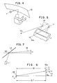
- Figs. 1 and 2 show a fundamental construction of the HUD in the prior art.
- the HUD is constituted of a display unit 11 installed at a center position of a dash board, for example, a (dioptric) optical system 12 such as a lens, and a catoptric system using a windshield glass 13.
- the display unit 11 employs LED, LCD and the like.
- a small image of the display unit 11 is enlarged by the optical system 12 and the virtual image optical system formed by the windshield glass 13, and is formed as a virtual image at a front position of the windshield glass 13.
- the virtual image (indication of speed, in this case) indicated by the display unit 11 of the HUD is perceived by a driver as if the display image were present at a fixed distance in front of an automobile 14.
- An image formation technique such that display information by LED or LCD and image information such as visible framework are formed in a fixed optical field is traditionally used in a camera finder, for example.
- a technique in the HUD is basically similar to such a display technique as mentioned above.
- the technique in the HUD includes some problems to be solved in such a point that the windshield glass is used as the catoptric system.
- One of the problems is caused by the use of the windshield glass as a half mirror having a relatively high transmittance.
- light beam directed from a point on the display unit ll through the optical system l2 to the windshield glass l3 is reflected on two interfaces between air and glass on the outside and inside of the automobile.
- the optical system of the HUD is primarily provided on the dash board, it is necessary to set large an incident and reflective angle to the windshield glass. As a result, reflective images as reflected on the two reflective surfaces are slipped to generate perception of a double image.
- the light generated from a point on the display unit ll is allowed to enter the windshield glass in the form of beam from an object point l7 on a virtual image formed by the optical system l2. Therefore, the beam is reflected on the two reflection interfaces of the windshield glass l3, and is allowed to enter driver's eyes l6 along two paths as shown by solid lines. This is caused by refraction at the interface between glass and air on the outside of the windshield glass. Owing to such a slip of the light path, the virtual image of the object point l7 is perceived double as shown by numerals l7 ⁇ , and accordingly, the driver cannot visibly perceive a clear display image.
- the windshield glass is treated by coating to form a mirror or half mirror having a high reflectance on an inner surface of the windshield glass.
- a lower area of the windshield glass plays an important role for the driver since he watches a fender part of the vehicle body so as to grasp a condition of the vehicle body. Therefore, if the visibility of the lower area of the windshield glass is hindered, the drivability is very reduced.
- poor visibility of the windshield glass causes hindrance in quick perception of any obstacle existing in front of the automobile, resulting in traffic danger.
- a HUD unit l including the display unit and the optical system is located at a central position of the dash board, and a virtual image is reflected to the driver sitting on a driver's seat of the automobile.
- reflective points l9 on the windshield glass of the same virtual image reaching a right eye l6R and a left eye l6L of the driver are present at different positions because of binocular parallax.
- Fig. 6 shows a plan view of arrangement of the driver's eyes l6R and l6L, the HUD unit (shown as an object point l′) and the reflective points on the windshield glass.
- the windshield glass is a plane glass for ease of explanation, there will be now described a problem under the following conditions.
- an average distance Ll between the right and left eyes is about 70 mm
- a distance Sl′ between a center position between both the eyes l6L and l6R and a middle point between the reflective points on the windshield glass is about 850 mm.
- the virtual image is directed from the HUD unit l on a lower side of the eyes, and a vertical difference H between a middle point l9′ between the reflective points and the eyes is about 30 mm.
- a distance L2 between a longitudinal line passing through the middle point l9′ and the central position of both the eyes is about 2l0 mm.
- the windshield glass is inclined by 28 degrees at the middle point l9′ with respect to a horizontal plane.
- a left reflective point l9L is slipped to a left lower position from a right reflective point l9R with respect to a plane formed by a y-axis extending in a vertical direction and a z-axis extending along a transverse direction of the automobile.
- a vertical difference between the reflective points l9L and l9R is 7.5 mm, while a transverse difference therebetween is 66.5 mm.
- a straight distance Sl between the central position of both the eyes and the reflective points is 876 mm.
- the reflective image on the windshield glass is perceived double because of the aforementioned binocular parallax, which is naturally dependent upon a transverse dimension of the image. Basically, it is hard to adjust the human eyes in the vertical direction, and accordingly, if the identical image is received by the eyes for a long time with such binocular parallax, there will occur eye strain to create a serious problem from the viewpoint of prevention of danger. Further, although curvature of the windshield glass in the vertical and transverse directions is not taken into consideration as to the binocular p arallax in the foregoing description, it will be appreciated that the slip of the virtual image is increased in the case that the curvature is considered.
- the HUD utilizing the windshield glass as a reflecting means has the problems of double reflection and binocular parallax. Unless the problems are solved, a clear display image cannot be visible perceived by the driver without eye strain.
- the optical system is designed such that an angle of light beam of the virtual image incident upon the windshield glass is not more than a monocular resolving power on the basis of reflective conditions of the windshield glass and a double image of the virtual image entering the windshield glass is not perceived by a driver, but a clear and high-quality display image may be visibly perceived by the driver and moreover eye strain due to binocular parallax is not generated, but a clear and high-quality display image may be visibly perceived by the driver. Further, high drivability and safety may be imparted to the automobile.
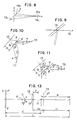
- Beams of light incident upon the windshield glass are intended to be nearly parallel to each other, so as to reduce the influence of the double reflection on the windshield glass. For instance, if a reflective image enters the windshield glass from a point at infinity (or a far point near infinity), beams of incident light become nearly parallel to each other as shown in Fig. 9, and an apparent distance of the image becomes infinite. As a result, parallax of beams reflected on two interfaces of the windshield glass l3 is decreased. If the parallax is suppressed within a resolving power of a human eye l6 (monocular), that is, within 2 to 5 minutes, a double image as slipped is not perceived.
- a human eye l6 monoocular
- the distance between a virtual image and the human eye for the purpose of elimination of perception of the double image is obtained in the following manner.
- Fig. l0 shows light beams of an object point l7 incident upon the windshield glass l3 and reflected light beams directed to the eye l6 with respect to two reflective interfaces of the windshield glass l3.
- the light beams reflected on the two interfaces take different paths.
- An angle formed by each of two light beams on the incident side and the reflective side is represented by ⁇ .
- An incident and reflective angle measured on the inside interface of the windshield glass is represented by ⁇ .
- a distance between a reflective point on the inside interface of the windshield glass and an incident point of the beam directed to the inside interface is represented by l1, while a distance between the reflective point and an incident point of the beam directed to an outside interface of the windshield glass is represented by l2.
- a distance between the object point 17 and the reflective point on the inside interface of the windshield glass is represented by D, while a distance between the reflective point and the eye 16 is represented by S. Then, the following equation is obtained by the law of sines.
- a reflective angle ⁇ on the outside interface of the windshield glass is given by the low of refraction in the following manner.
- the distance D may be required to be more than the range of 500 to 2000 mm under the condition of a general driving position, installation position of the device and angle of the windshield glass. Naturally, if the distance D exceeds this distance, and approaches to infinity, the double image is eliminated.
- Fig. l2 shows only a display unit ll formed by an LCD unit and an optical system l2 for the purpose of simplicity of the HUD unit l, in which a housing of the HUD unit, a dash board and the other elements are omitted.
- the display unit ll is arranged on a light axis of the optical system l2.
- the light axis of the optical system l2 is arranged so as to reflect the virtual image of the display image of the display unit ll from a position below the inclined windshield glass l3 having curvature R to a driver's eye existing at a substantially horizontally rear position.
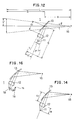
- the windshield glass is regarded as a plane glass. Further, it is assumed that a distance between the eye l6 and the virtual image present at a front position of the windsheild glass l3 is L; a distance between the eye l6 and the windshield glass l3 is C1; a distance between the optical system l2 and the windsheild glass l3 is C2; and a distance between the windshield glass l3 and the virtual image is S.
- the windshield glass l3 is assumed to be plane, it is not necessary to take magnification of the windshield glass l3 into consideration.
- a distance between the windshield glass l3 and the virtual image formed on a rear side of the display unit ll and the optical system is equal to the distance S between the windshield glass l3 and the virtual image formed on a front side of the windshield glass l3.
- a size of both the virtual images is also equal to each other.
- a lateral magnification ⁇ is given by the following equation.
- the distance x′ is given by the following equation with respect to a focal distance f and the distance x between the object PQ and the focal point F.
- the distance L is dependent upon not only the focal distance of the optical system and the position of the object, but also the position of the driver. Therefore, it is necessary to consider the position of the driver, so as to set an apparent distance of the image.
- x may be obtained by setting a value of L required for eliminating the double image, and determining p and f.
- the display unit ll is located at the distance x as obtained to provide the on-vehicle HUD which may elimiante the double image.
- the windshield glass is generally so curved as to project toward a front side of an automobile, and functions as a concave mirror.
- no curvature of the windshield glass is taken into consideration. Therefore, even if the distances f and x in Equation (8) are set so as to form a display image at a predetermined distance, the double image cannot be effectively eliminated as desired.
- the optical system l2 and the windshield glass l3 are synthesized with each other to obtain a synthetic optical system 20 as shown in Fig. l5 which is equivalent to Fig. l4. Then, obtained are a synthetic focal distance f0 of the synthetic optical system 20 and a distance y between a center point H of the synthetic optical system 20 and a center point O of the optical system l2 shown in Fig. l3 so as to determine a mounting position of the display unit ll.
- the windshield glass l3 having curvature R functions as a lens having a focal distance R/2.
- the synthetic focal distance f0 obtained by synthesizing the windshield glass l3 and the optical system l2 having a focal distance f′ may be given by the following equation.
- the distance y may be given by the following equation.
- the synthetic focal distance f0 of the synthetic optical system 20 shown in Fig. l5 may be obtained by substituting these values into Equation (l0) as follows:
- the position of the synthetic optical system 20 is determined at the distance of about 29.8 mm from the optical system l2.
- the appa rent distance capable of suppressing image slip created by the double reflection on the windshield glass to a level less than the monocular resolving power is first obtained from each position of the windshield glass, the driver and the HUD unit. Then, the constitution of the optical system and the distance between the optical system and the display unit are determined.
- the apparent distance of about 20 m for the virtual image by the HUD may be obtained to thereby reduce the slip of the double image created by the double reflection on the windshield glass to such a degree that the slip is not perceived.
- extension of the apparent distance is preferable in view of the fact that a watching point in driving is present at a distance relatively far away from the driver.
- the display unit ll is located at the distance of l97.9 mm from the optical system l2.
- the display unit ll is located at the distance of l80.9 mm from the optical system l2.
- the difference of l7 mm in the position of the display unit ll is present between the present invention and the prior art. The difference can cause incapabilities of formation of a virtual image at a desired far point and elimination of the double image. Unless the virtual image may be formed at a desired far point, there is a possibility that the driver cannot visibly perceive a display image at an apparent distance in driving.
- the optical system preferably includes a large aperture lens so that the overall display image may be visibly perceived through the optical system even when a driver moves his head or adjusts his seat.
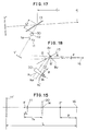
- mirrors la and lb may be provided between the display unit ll and the optical system l2 as shown in Fig. l6 so as to bend the light axis and decrease the overall length of the HUD unit.
- the reflective point on the windshield glass of the light image of the HUD which enters the right and left eyes is slipped by 66.5 mm in a horizontal direction and 7.5 mm in a vertical direction, and the binocular parallax ⁇ in the vertical direction is 0.49°.
- the binocular parallax in the horizontal direction provides stereoscopic vision, there will not occur so serious problem unless the horizontal slip of the reflective point is corrected. Accordingly, it is possible to obtain a satisfactory display image by correcting the binocular parallax in the vertical direction only even when oblique reflection is conducted.
- the binocular parallax in the vertical direction will reference to Figs 5 and 6 may be eliminated by upwardly moving the reflective point for the left eye by the distance of 7.5 mm. As a result, the display image may be visualized more clearly.
- the preferred embodiment employs a prism 30 to move light beam directed from the optical system of the HUD unit through the windshield glass to the left eye.
- the image of the display unit ll is once reflected on a mirror la prior to entering the optical system l2 for the purpose or reducing a size of the HUD unit in the vertical direction of the dash board.
- Fig. l8 which shows details of the operation of the prism 30, light beam K L entering the left eye prior to correction is reflected at a reflective point B located below a reflective point A of light beam K R entering the right eye.
- the angle ⁇ formed between both the light beams after reflection means the binocular parallax in the vertical direction.
- the prism 30 is of a sectional shape such that an upper surface only is inclined and a portion on a front side of the vehicle body is thicker than that on a rear side thereof. Further, the prism 30 has different vertical angles such that the vertical angle on the left side where the light beam entering the left eye passes is larger, while the vertical angle on the right side where the light beam entering the right eye passes is smaller. Thus, the upper surface of the prism is curved.
- the section of the prism 30 shown in Fig. l8 is a section where the light beam K L entering the left eye passes.
- the light beam K R entering the right eye passes through a section of the prism 30 present on a back side of the drawing (corresponding to a right-hand side of the vehicle body).
- the vertical angle of the prism 30 at the section where the light beam K R passes is smaller, and the light beam K R passes at the substantially same position as with the case that the correction by the prism is not carried out.
- the light beam K L ′ passes through the section having a larger vertical angle, and is refracted by the correction angle ⁇ . Then, the light beam K L ′ is reflected at a point B′ present at the same level as of a reflective point A of the light beam K R .
- both the light beams K L ′ and K R entering the left and right eyes advance on a horizontal plane envolving both the eyes by the operation of the prism, thereby eliminating the binocular parallax in the vertical direction and obtaining a clear display image.
- a tilt angle of the light beam K L ′ is different from that of the light beam K R prior to reflection on the windshield glass, a direction of a perpendicular B v at the reflective point B′ is naturally different from that of a perpendicular A v at the reflective point A.
- a width b of the prism 30 is about l30 mm, and a depth a is about 53 mm in consideration of an aspect ratio of the display image, provided that an effective diameter ⁇ is l20 mm, and a horizontal distance between both the reflective points A and B is l.80 times 66.5 mm.
- a thickness t is l.0 mm, and a refractive index n of the prism 30 made of glass is l.492.
- a necessary refractive angle with respect to a maximum vertical angle ⁇ 0 on the x-axis and the refractive index n in Fig. l9 is as follows:
- a height (thickness) z of the prism 30 is represented as follows:
- Fig. 20 shows a contour of the height z of the prism on the x-y plane according to Equation (14). As is apparent from Fig. 20, the upper surface of the prism 30 is curved in such a manner that a left front portion is thick, while a right rear portion is thin.
- the binocular parallax in the vertical direction may be eliminated to enable the driver to visibly perceive a high-quality display image without eye strain.
- curvature of the windshield glass is not taken into consideration in Figs. 19 and 20, the curvature may be reflected on the shape of the prism to obtain a display image with no parallax in the case that the windshield glass is curved, and especially, it is largely curved in a transverse direction.
- the mirror 1a is provided between the display unit 11 and the optical system 12 in the foregoing preferred embodiment shown in Fig. 17, the display unit 11 may be located on the light axis of the optical system 12 without providing the mirror 1a.
- the aforementioned preferred embodiment employs a single convex lens for the optical system 12, a combination lens formed by combining a plurality of lenses may be of course used for the optical system 12.
- an angle formed by light beams of the virtual image to enter the windshield is rendered less than a monocular resolving power on an assumption that the thickness of the windshield glass is constant in the above embodiment whereas the effect of rendering said angle may be obtained by making the windshield glass thinner.
Landscapes
- Physics & Mathematics (AREA)
- General Physics & Mathematics (AREA)
- Optics & Photonics (AREA)
- Instrument Panels (AREA)
Claims (6)
- Im Fahrzeug eingebaute Anzeigevorrichtung (1), das eine Windschutzscheibe besitzt, umfassend:- Anzeigemittel (11) zum Anzeigen unterschiedlicher Informationen;- ein optisches System (12) mit einer optischen Achse und zur Bildung eines virtuellen Anzeigebildes des Anzeigemittels, wobei die Windschutzscheibe (13) des Fahrzeuges zwei virtuelle Bilder des virtuellen Anzeigebildes durch Reflexion des virtuellen Anzeigebildes an seinen zwei gegenüberliegenden Hauptschnittflächen bildet, und wobei das optische System ausgelegt ist, um den winkelmäßigen Abstand zwischen den zwei durch die Windschutzscheibe gebildeten virtuellen Bildern auf einen geringeren als vorbestimmten Wert zu reduzieren, der der monokularen Auflösungskraft eines Betrachters entspricht,dadurch gekennzeichnet, daß die Vorrichtung ferner ein optisches Mittel (30) umfaßt, das zwischen dem optischen System und der Windschutzscheibe angeordnet ist, und wobei das optische Mittel eine erste und zweite Hauptfläche und einen in einer parallelen Ebene zur optischen Achse verlaufenden Querschnitt besitzt, der prismatisch ist, und wobei die zweite Hauptfläche der Windschutzscheibe gegenüberliegt und auf solche Weise gekrümmt ist, das sich der Prisma-Winkel (80), der durch die beiden Hauptflächen gebildet ist, allmählich in Abhängigkeit von der Entfernung zwischen der Ebene und der optischen Achse verändert, um die vertikale binokulare Parallaxe der Vorrichtung für den Betrachter zu korrigieren.
- Im Fahrzeug eingebaute Anzeigevorrichtung nach Anspruch 1, bei der der vorbestimmte Wert einer monokularen Auflösungskraft von 5 Minuten entspricht.
- Im Fahrzeug eingebaute Anzeigevorrichtung nach Anspruch 1, bei der das optische System mit der Windschutzscheibe zusammenwirkt, die eine Krümmung unter Ausbildung eines zusammengesetzten optischen Systems (20) bildet.
- Im Fahrzeug eingebaute Anzeigevorrichtung nach Anspruch 1, bei der das optische System ein Linsensystem umfaßt, das ein großes Öffnungsverhältnis besitzt, so daß es dem Betrachter gestattet, seinen Kopf zu bewegen.
- Im Fahrzeug eingebaute Anzeigevorrichtung nach Anspruch 1, ferner umfassend:
ein katoptrisches System (1a,1b), das zwischen den Anzeigemitteln und dem optischen System zum Reflektieren des virtuellen Anzeigebildes der Anzeigemittel in Richtung auf das optische System vorgesehen ist. - Im Fahrzeug eingebaute Anzeigevorrichtung nach Anspruch 1, bei der das optische System ein virtuelles Anzeigebild des Anzeigemittels bei einer Entfernung von 3m oder mehr von der Windschutzscheibe bildet.
Applications Claiming Priority (4)
| Application Number | Priority Date | Filing Date | Title |
|---|---|---|---|
| JP61011123A JPS62173336A (ja) | 1986-01-23 | 1986-01-23 | 車載用ヘツドアツプデイスプレイ装置 |
| JP11123/86 | 1986-01-23 | ||
| JP68467/86 | 1986-03-28 | ||
| JP61068467A JPH0659787B2 (ja) | 1986-03-28 | 1986-03-28 | 車載用ヘツドアツプデイスプレイ装置 |
Publications (3)
| Publication Number | Publication Date |
|---|---|
| EP0229876A2 EP0229876A2 (de) | 1987-07-29 |
| EP0229876A3 EP0229876A3 (en) | 1988-04-27 |
| EP0229876B1 true EP0229876B1 (de) | 1992-04-08 |
Family
ID=26346518
Family Applications (1)
| Application Number | Title | Priority Date | Filing Date |
|---|---|---|---|
| EP86112835A Expired EP0229876B1 (de) | 1986-01-23 | 1986-09-17 | Im Fahrzeug eingebaute Anzeigevorrichtung |
Country Status (3)
| Country | Link |
|---|---|
| US (2) | US4787711A (de) |
| EP (1) | EP0229876B1 (de) |
| DE (1) | DE3684772D1 (de) |
Families Citing this family (53)
| Publication number | Priority date | Publication date | Assignee | Title |
|---|---|---|---|---|
| DE3822222A1 (de) * | 1988-07-01 | 1990-01-04 | Bosch Gmbh Robert | Einrichtung fuer head-up-displays an kraftfahrzeugen |
| JPH0651451B2 (ja) * | 1987-03-17 | 1994-07-06 | 矢崎総業株式会社 | 車両用表示装置 |
| JPH0626434Y2 (ja) * | 1987-03-18 | 1994-07-20 | 矢崎総業株式会社 | 車両用ヘツドアツプ表示装置 |
| GB2204421B (en) * | 1987-04-15 | 1991-01-16 | Yazaki Corp | Display apparatus for a vehicle |
| GB2203883B (en) * | 1987-04-16 | 1990-07-18 | Yazaki Corp | Display apparatus for automotive vehicle |
| GB2203855B (en) * | 1987-04-16 | 1990-10-03 | Yazaki Corp | Display apparatus for a vehicle |
| DE3812648A1 (de) * | 1987-04-16 | 1988-11-03 | Yazaki Corp | Anzeigevorrichtung fuer ein fahrzeug |
| JPS6467428A (en) * | 1987-09-07 | 1989-03-14 | Yazaki Corp | Display device for vehicle |
| DE3735125A1 (de) * | 1987-10-16 | 1989-05-03 | Bayerische Motoren Werke Ag | Vorrichtung in kraftfahrzeugen zum einspiegeln von optischen informationssignalen |
| US5028912A (en) * | 1988-02-03 | 1991-07-02 | Yazaki Corporation | Display apparatus for automotive vehicle |
| US5034732A (en) * | 1988-02-05 | 1991-07-23 | Yazaki Corporation | Head up display apparatus for automotive vehicle |
| JP2650358B2 (ja) * | 1988-10-06 | 1997-09-03 | 株式会社ニコン | 半透過部材を有する光学装置 |
| US4973139A (en) * | 1989-04-07 | 1990-11-27 | Hughes Aircraft Company | Automotive head-up display |
| US5013135A (en) * | 1989-07-10 | 1991-05-07 | Matsushita Electric Industrial Co., Ltd. | Head-up display with two fresnel lenses |
| US5812332A (en) * | 1989-09-28 | 1998-09-22 | Ppg Industries, Inc. | Windshield for head-up display system |
| MX171971B (es) * | 1989-10-16 | 1993-11-24 | Libbey Owens Ford Co | Panel exhibidor para un parabrisas de vehiculo |
| US5212471A (en) * | 1989-10-27 | 1993-05-18 | Hughes Aircraft Company | Polarized heads up display |
| JPH0643827Y2 (ja) * | 1990-01-18 | 1994-11-14 | 矢崎総業株式会社 | 表示装置 |
| IT1240796B (it) * | 1990-03-12 | 1993-12-17 | Siv Soc Italiana Vetro | Vetro per autoveicoli, atto ad essere usato come schermo solare e come combinatore di immagini. |
| IT1242140B (it) * | 1990-09-20 | 1994-02-16 | Siv Soc Italiana Vetro | Dispositivo viasualizzatore del tipo a testa eretta per la presentazione di dati a bordo di autoveicoli |
| WO1993008496A1 (en) * | 1991-10-24 | 1993-04-29 | Arnon, Tamar | Biocular head-up display with separated fields |
| DE4317896B4 (de) * | 1992-05-29 | 2007-10-18 | Yazaki Corp. | Holographischer Spiegel vom nichtregelmäßigen Reflexionstyp und Verfahren zu seiner Herstellung sowie eine Anzeigevorrichtung vom Reflexionstyp für Fahrzeuge |
| US5535025A (en) * | 1994-02-01 | 1996-07-09 | Hughes Training, Inc. | Helmet mounted off axis liquid crystal display with a fiber optic wedge and a curved reflector |
| FR2717795B1 (fr) * | 1994-03-22 | 1996-05-24 | Saint Gobain Vitrage | Vitrage pour véhicule et feuille de matière plastique utilisée dans ce vitrage. |
| US20070135982A1 (en) | 1995-06-07 | 2007-06-14 | Automotive Technologies International, Inc. | Methods for Sensing Weight of an Occupying Item in a Vehicular Seat |
| US20060284839A1 (en) * | 1999-12-15 | 2006-12-21 | Automotive Technologies International, Inc. | Vehicular Steering Wheel with Input Device |
| US7860626B2 (en) * | 1995-06-07 | 2010-12-28 | Automotive Technologies International, Inc. | Vehicular heads-up display system with adjustable viewing |
| US5912700A (en) * | 1996-01-10 | 1999-06-15 | Fox Sports Productions, Inc. | System for enhancing the television presentation of an object at a sporting event |
| US6847336B1 (en) * | 1996-10-02 | 2005-01-25 | Jerome H. Lemelson | Selectively controllable heads-up display system |
| US5953077A (en) * | 1997-01-17 | 1999-09-14 | Fox Sports Productions, Inc. | System for displaying an object that is not visible to a camera |
| US6580562B2 (en) * | 2000-07-24 | 2003-06-17 | Yazaki Corporation | On-vehicle display unit |
| JP2002202475A (ja) * | 2000-12-28 | 2002-07-19 | Yazaki Corp | 車両用表示装置 |
| US20080198372A1 (en) * | 2007-02-21 | 2008-08-21 | Spatial Photonics, Inc. | Vehicle headlight with image display |
| JP2011053386A (ja) * | 2009-09-01 | 2011-03-17 | Seiko Epson Corp | 表示装置、電子機器、投射型映像装置 |
| US8299938B2 (en) * | 2009-09-08 | 2012-10-30 | Rosemount Inc. | Projected instrument displays for field mounted process instruments |
| DE102011118134B4 (de) * | 2011-11-10 | 2021-12-16 | Kostal Automobil Elektrik Gmbh & Co. Kg | Kameraanordnung für ein Kraftfahrzeug |
| GB2498715A (en) * | 2012-01-20 | 2013-07-31 | Bae Systems Plc | Head up display providing two non-coincident virtual images |
| JP5941292B2 (ja) * | 2012-02-10 | 2016-06-29 | 矢崎総業株式会社 | 車両用表示装置 |
| EP3031656B1 (de) | 2014-12-10 | 2018-01-03 | Ricoh Company, Ltd. | Informationsbereitstellungsvorrichtung, informationsbereitstellungsverfahren und trägermedium-speicherinformationsbereitstellungsprogramm |
| US10046703B2 (en) | 2014-12-12 | 2018-08-14 | Serge B. HOYDA | System and process for viewing in blind spots |
| US11124116B2 (en) | 2014-12-12 | 2021-09-21 | Serge B. HOYDA | System and process for viewing in blind spots |
| US10125918B2 (en) | 2014-12-12 | 2018-11-13 | Serge B. HOYDA | Mounting system for a camera |
| US11518309B2 (en) | 2014-12-12 | 2022-12-06 | Serge Hoyda LLC | System and process for viewing in blind spots |
| US10138672B2 (en) | 2014-12-12 | 2018-11-27 | Serge B. HOYDA | Mounting system for a camera |
| EP3244253B1 (de) * | 2015-06-26 | 2021-03-24 | Panasonic Intellectual Property Management Co., Ltd. | Headup-anzeigevorrichtung und mit der headup-anzeige ausgestatteter, beweglicher körper |
| FR3067821B1 (fr) * | 2017-06-19 | 2021-03-12 | Peugeot Citroen Automobiles Sa | Dispositif d’affichage tete-haute pour vehicule |
| JP6593393B2 (ja) * | 2017-07-11 | 2019-10-23 | 株式会社Jvcケンウッド | 虚像表示装置 |
| JP2019086766A (ja) | 2017-11-09 | 2019-06-06 | 日東電工株式会社 | ヘッドアップディスプレイ装置 |
| US20190161010A1 (en) * | 2017-11-30 | 2019-05-30 | Panasonic Automotive Systems Company Of America, Division Of Panasonic Corporation Of North America | High visibility head up display (hud) |
| JP6995883B2 (ja) * | 2017-12-25 | 2022-01-17 | 富士フイルム株式会社 | ヘッドアップディスプレイ装置 |
| JP6593462B2 (ja) * | 2018-01-12 | 2019-10-23 | 株式会社Jvcケンウッド | 虚像表示装置 |
| CN110794580B (zh) * | 2018-08-03 | 2022-04-05 | 深圳前海智云谷科技有限公司 | 汽车抬头显示系统及其安装方法和消除重影的方法 |
| JP6749981B2 (ja) * | 2018-10-01 | 2020-09-02 | 本田技研工業株式会社 | 表示装置、表示制御方法、およびプログラム |
Family Cites Families (15)
| Publication number | Priority date | Publication date | Assignee | Title |
|---|---|---|---|---|
| US2750833A (en) * | 1956-06-19 | Inven tor | ||
| US1787269A (en) * | 1928-04-23 | 1930-12-30 | Zeiss Carl Fa | Device for partial deflection of a conical pencil of imaging rays |
| US3498691A (en) * | 1967-12-26 | 1970-03-03 | Razdow Lab Inc | Parallax-free telescopic sight |
| GB1418891A (en) * | 1972-01-28 | 1975-12-24 | Nat Res Dev | Headup display aparatus |
| US3778548A (en) * | 1972-09-06 | 1973-12-11 | Omi Ottico Mecc Italiana | Optical apparatus for collimation to infinity of two luminous images whose frequencies fall within different spectral bands |
| SE371491B (de) * | 1973-03-26 | 1974-11-18 | J Ekstrand | |
| US3887273A (en) * | 1973-07-27 | 1975-06-03 | Friedemann Conrad J | Speedometer optical projection system |
| US3899241A (en) * | 1973-12-11 | 1975-08-12 | Ppg Industries Inc | Visual display windshield |
| US3940204A (en) * | 1975-01-23 | 1976-02-24 | Hughes Aircraft Company | Optical display systems utilizing holographic lenses |
| GB1577618A (en) * | 1976-12-03 | 1980-10-29 | Smiths Industries Ltd | Display systems |
| US4530564A (en) * | 1980-08-18 | 1985-07-23 | Hughes Aircraft Company | Method and apparatus for production of holographic optical elements |
| US4582389A (en) * | 1982-02-18 | 1986-04-15 | Flight Dynamics, Inc. | Holographic device |
| US4447128A (en) * | 1982-12-03 | 1984-05-08 | Hughes Aircraft Company | Diffraction head up display solar radiation filter |
| US4613200A (en) * | 1984-07-09 | 1986-09-23 | Ford Motor Company | Heads-up display system with holographic dispersion correcting |
| US4632508A (en) * | 1984-08-01 | 1986-12-30 | Grumman Aerospace Corporation | Windscreen deviation correcting pilot display |
-
1986
- 1986-09-12 US US06/907,148 patent/US4787711A/en not_active Expired - Lifetime
- 1986-09-17 EP EP86112835A patent/EP0229876B1/de not_active Expired
- 1986-09-17 DE DE8686112835T patent/DE3684772D1/de not_active Expired - Lifetime
-
1988
- 1988-06-02 US US07/201,411 patent/US4892386A/en not_active Expired - Lifetime
Also Published As
| Publication number | Publication date |
|---|---|
| US4892386A (en) | 1990-01-09 |
| EP0229876A2 (de) | 1987-07-29 |
| DE3684772D1 (de) | 1992-05-14 |
| US4787711A (en) | 1988-11-29 |
| EP0229876A3 (en) | 1988-04-27 |
Similar Documents
| Publication | Publication Date | Title |
|---|---|---|
| EP0229876B1 (de) | Im Fahrzeug eingebaute Anzeigevorrichtung | |
| US6104552A (en) | Vehicular rearview mirror assembly with forward vision optical system | |
| JP3573765B2 (ja) | 車両のヘッドアップディスプレイ装置 | |
| JPH0659787B2 (ja) | 車載用ヘツドアツプデイスプレイ装置 | |
| US6315419B1 (en) | Automotive rearview mirror having a main viewing section and an auxiliary blindzone-viewing section | |
| JP2562263B2 (ja) | ヘッドアップディスプレー装置 | |
| KR20020021091A (ko) | 헤드업 디스플레이 | |
| JPH07504375A (ja) | 乗物用後方視野システム | |
| EP0279221B1 (de) | Rückblickspiegel | |
| US5731903A (en) | Virtual image instrument panel display | |
| JPH085349B2 (ja) | 自動車の画像再生装置 | |
| GB2458898A (en) | A head up display system with ghost image elimination means | |
| CN219676374U (zh) | 显示装置、抬头显示装置和交通工具 | |
| EP0535876A1 (de) | Blickrichtungsanzeige für Fahrzeug | |
| US4182552A (en) | Side view mirror employing prism for blind spot correction | |
| CN113970845A (zh) | 多焦平面抬头显示设备 | |
| JP4213223B2 (ja) | 光学式後方展望システム | |
| EP3534202B1 (de) | Virtuelle bildanzeigevorrichtung | |
| JPH0456633A (ja) | ヘッドアップディスプレー装置 | |
| JP2002031774A (ja) | 車両用ヘッドアップディスプレイ | |
| JPH0571415B2 (de) | ||
| JP2019078794A (ja) | 乗物用表示装置 | |
| JP2970056B2 (ja) | 光学装置 | |
| JPH08169260A (ja) | 表示システムおよびヘッドアップディスプレイ | |
| USRE30673E (en) | Side view mirror employing prism for blind spot correction |
Legal Events
| Date | Code | Title | Description |
|---|---|---|---|
| PUAI | Public reference made under article 153(3) epc to a published international application that has entered the european phase |
Free format text: ORIGINAL CODE: 0009012 |
|
| AK | Designated contracting states |
Kind code of ref document: A2 Designated state(s): DE FR GB |
|
| PUAL | Search report despatched |
Free format text: ORIGINAL CODE: 0009013 |
|
| AK | Designated contracting states |
Kind code of ref document: A3 Designated state(s): DE FR GB |
|
| 17P | Request for examination filed |
Effective date: 19880801 |
|
| 17Q | First examination report despatched |
Effective date: 19900810 |
|
| GRAA | (expected) grant |
Free format text: ORIGINAL CODE: 0009210 |
|
| AK | Designated contracting states |
Kind code of ref document: B1 Designated state(s): DE FR GB |
|
| REF | Corresponds to: |
Ref document number: 3684772 Country of ref document: DE Date of ref document: 19920514 |
|
| ET | Fr: translation filed | ||
| PLBE | No opposition filed within time limit |
Free format text: ORIGINAL CODE: 0009261 |
|
| STAA | Information on the status of an ep patent application or granted ep patent |
Free format text: STATUS: NO OPPOSITION FILED WITHIN TIME LIMIT |
|
| 26N | No opposition filed | ||
| REG | Reference to a national code |
Ref country code: GB Ref legal event code: IF02 |
|
| PGFP | Annual fee paid to national office [announced via postgrant information from national office to epo] |
Ref country code: FR Payment date: 20040908 Year of fee payment: 19 |
|
| PGFP | Annual fee paid to national office [announced via postgrant information from national office to epo] |
Ref country code: DE Payment date: 20040909 Year of fee payment: 19 |
|
| PGFP | Annual fee paid to national office [announced via postgrant information from national office to epo] |
Ref country code: GB Payment date: 20040915 Year of fee payment: 19 |
|
| PG25 | Lapsed in a contracting state [announced via postgrant information from national office to epo] |
Ref country code: GB Free format text: LAPSE BECAUSE OF NON-PAYMENT OF DUE FEES Effective date: 20050917 |
|
| PG25 | Lapsed in a contracting state [announced via postgrant information from national office to epo] |
Ref country code: DE Free format text: LAPSE BECAUSE OF NON-PAYMENT OF DUE FEES Effective date: 20060401 |
|
| GBPC | Gb: european patent ceased through non-payment of renewal fee |
Effective date: 20050917 |
|
| PG25 | Lapsed in a contracting state [announced via postgrant information from national office to epo] |
Ref country code: FR Free format text: LAPSE BECAUSE OF NON-PAYMENT OF DUE FEES Effective date: 20060531 |
|
| REG | Reference to a national code |
Ref country code: FR Ref legal event code: ST Effective date: 20060531 |