EP0229985A2 - Moules de vulcanisation de pneus - Google Patents
Moules de vulcanisation de pneus Download PDFInfo
- Publication number
- EP0229985A2 EP0229985A2 EP86117308A EP86117308A EP0229985A2 EP 0229985 A2 EP0229985 A2 EP 0229985A2 EP 86117308 A EP86117308 A EP 86117308A EP 86117308 A EP86117308 A EP 86117308A EP 0229985 A2 EP0229985 A2 EP 0229985A2
- Authority
- EP
- European Patent Office
- Prior art keywords
- mould
- fact
- facing
- tyre
- elements
- Prior art date
- Legal status (The legal status is an assumption and is not a legal conclusion. Google has not performed a legal analysis and makes no representation as to the accuracy of the status listed.)
- Withdrawn
Links
Images

Classifications
-
- B—PERFORMING OPERATIONS; TRANSPORTING
- B29—WORKING OF PLASTICS; WORKING OF SUBSTANCES IN A PLASTIC STATE IN GENERAL
- B29D—PRODUCING PARTICULAR ARTICLES FROM PLASTICS OR FROM SUBSTANCES IN A PLASTIC STATE
- B29D30/00—Producing pneumatic or solid tyres or parts thereof
- B29D30/06—Pneumatic tyres or parts thereof (e.g. produced by casting, moulding, compression moulding, injection moulding, centrifugal casting)
- B29D30/0601—Vulcanising tyres; Vulcanising presses for tyres
- B29D30/0606—Vulcanising moulds not integral with vulcanising presses
-
- B—PERFORMING OPERATIONS; TRANSPORTING
- B29—WORKING OF PLASTICS; WORKING OF SUBSTANCES IN A PLASTIC STATE IN GENERAL
- B29C—SHAPING OR JOINING OF PLASTICS; SHAPING OF MATERIAL IN A PLASTIC STATE, NOT OTHERWISE PROVIDED FOR; AFTER-TREATMENT OF THE SHAPED PRODUCTS, e.g. REPAIRING
- B29C33/00—Moulds or cores; Details thereof or accessories therefor
- B29C33/0038—Moulds or cores; Details thereof or accessories therefor with sealing means or the like
-
- B—PERFORMING OPERATIONS; TRANSPORTING
- B29—WORKING OF PLASTICS; WORKING OF SUBSTANCES IN A PLASTIC STATE IN GENERAL
- B29C—SHAPING OR JOINING OF PLASTICS; SHAPING OF MATERIAL IN A PLASTIC STATE, NOT OTHERWISE PROVIDED FOR; AFTER-TREATMENT OF THE SHAPED PRODUCTS, e.g. REPAIRING
- B29C43/00—Compression moulding, i.e. applying external pressure to flow the moulding material; Apparatus therefor
- B29C43/32—Component parts, details or accessories; Auxiliary operations
- B29C43/36—Moulds for making articles of definite length, i.e. discrete articles
- B29C43/38—Moulds for making articles of definite length, i.e. discrete articles with means to avoid flashes
-
- B—PERFORMING OPERATIONS; TRANSPORTING
- B29—WORKING OF PLASTICS; WORKING OF SUBSTANCES IN A PLASTIC STATE IN GENERAL
- B29L—INDEXING SCHEME ASSOCIATED WITH SUBCLASS B29C, RELATING TO PARTICULAR ARTICLES
- B29L2030/00—Pneumatic or solid tyres or parts thereof
Definitions
- the present invention concerns devices for the moulding of elastomeric or plastomeric articles, that henceforth, in this text, shall be defined as 'moulds' and, in particular, those moulds used for moulding and vulcanizing tyres.
- the above-said moulding devices are generally formed by at least two shells, each one provided with an open hollow, that are alternatively joined and separated from the other, so much so that when coupled together they realize a cavity, closed towards the outside ambient, which defines the outer form of the article to be produced.
- the manufacturing process can be carried out through injection or through moulding.
- a suitable material having specific characteristics of fluidity, is injected, under high pressure and generally at a high temperature, into the above-described mould cavity with its thus acquiring the form. Once the solidification has taken place, the mould is opened for allowing to remove the article produced in this way.
- the article to be produced has a complex constitution, with comprising many diverse structural elements such as, for example, a tyre
- this article is pre-manufactured apart, to then be inserted into the moulding cavity.
- a high temperature and high pressure fluid is introduced that renders the elastomeric material of the tyre to become plastic, and presses it against the mould walls, with causing the tyre to acquire its final configuration and its foreseen aesthetic aspect.
- burrs constitute a great economic disadvantage since they lessen the aesthetic aspect with thus damaging the product's image for the buyer. Eliminating burrs from the product, brings about even further working operations with consequently, increasing production costs. Apart from this fact, when the geometrical dimensions are considerable, for example, of over one millimetre in thickness and width, they cause a shrinkage of elastomeric material with so compromising the qualitative 'behaviour' characteristics of the finished product.
- Said burrs manage to form more easily in proportion to just how fluid the material is, that is injected or moulded, and although the comprising elements of the mould are strongly pressed together for so resisting the pressure thrusts acting from inside the mould.
- the mould elements intended for reciprocally contacting each other always present angular errors of flatness, in their facing surfaces, which generate coupling irregularities, in the order of one tenth of a millimetre, that are sufficient enough for allowing the material to pass through into the interspace thus created, with the consequent forming of a burr.
- the above-said angular errors, and the other dimensional working tolerances constitute another important cause for the formation of the above-said burrs because of the fact that some pairs of surfaces come into reciprocal contact prior to other parts, with thus blocking any whatseover further movement of the mould-elements, between which therefore, there remains a space that is sufficie nt for said burrs to form.
- Such moulds are substantially comprised by two annular, coaxial and contrasting slabs, that block the tyre sidewalls, and by a crown of circumferential sectors that close radially against the above-said slabs in such a way as to mould the tyre's crown portion.
- each of these sectors present axially circumferential lower and upper surfaces, abutting against the slabs, and radial coupling surfaces in the circumferential direction, against the adjacent sectors.
- This complex of reciprocally contacting elements generates two continuous, circumferential burrs on the tyre in the connecting zone between slabs and sectors, and plurality of radial burrs extended over the entire width of the treadband, in the contacting zone between adjacent sectors; all of these becoming even more imposing when the tyre to be produced and hence, the mould, is broader.
- the aim of the present invention is a device, for moulding elastomeric or plastomeric articles, that allows for preventing the formation of the above-said burrs, with also guaranteeing the elimination of all the clearances existing between the diverse elements that are in reciprocal contact, and this without requiring a more accurate processing of the surfaces of the elements that comprise the mould.
- what forms the object of the present invention is a device for moulding elastomeric or plastomeric articles comprising at least two substantially hollow elements, which are reciprocally shiftable, one with respect to the other, for being taken alternatively from a first 'shut configuration' of reciprocal contact, whereby they delimit a cavity that is closed against the outside ambient, that is apt for containing the article to be moulded, and a second, reciprocally spaced apart 'open configuration' for allowing to introduce and/or to remove said article from the said cavity, characterized by the fact of comprising means for preventing during the passage from said 'open configuration' to said 'shut configuration', any simultaneous coupling, that is extended for the entire width of the reciprocally facing surfaces of said elements, while they impose a reciprocal coupling, of an increasable width, between said facing surfaces.
- Said means with which at least one of the two reciprocally contacting surfaces must be provided, are means which are elastically and plastically deformable on the new device, for which reson they result as being at least partially, permanently deformed plastically, after the first closing operation of said device, and they deform cyclically and elastically during each successive passage from said open configuration to said closed configuration, and vice-versa.
- said means are formed by the inclination of one of the said facing surfaces with respect to the corresponding surface, in ratio to the relative shifting between said surfaces, in such a manner that the contact between said facing surfaces, is established along a narrow rim zone of said cavity, the distance between said facing surfaces increasing progressively in the orthogonal direction to said shifting direction.
- said means comprise a projecting part made on at least one of the above-said reciprocally facing surfaces and having a lesser area to that of the remaining surface portion, that is extended along a trajectory substantially following the profile of the concave part of the corresponding element.
- the above-said mould comprises two opposed hollow, substantially concave elements, that are reciprocally shiftable axially, in both senses, apt for delimiting between them, a substantially toric cavity, in a position of reciprocal contact, and this mould is characterized by the fact that the surface of one of said hollow elements, that faces the element opposite, is a conical surface having its apex on the axis of symmetry of said mould and, when the material of said hollow element is steel, the angular opening of said conical surface is not less than 87° sexagesimals.
- the surface of one of the said hollow elements, that faces the element opposite is instead, provided with a continuous annular projection delimiting the concave part of the corresponding element.
- the mould is of the centripetal type, i.e. comprising two annular, coaxial and opposed, substantially concave elements defined as cheeks, axially and reciprocally shiftable in both senses, apt for moulding the sidewalls of said tyre, and a plurality of substantially concave radial elements, circumferentially disposed co-axially to said mould, around the said cheeks, defined as sectors, axially shiftable in both senses, with respect to said cheeks, apt for moulding the crown portion of the said tyre, then the circumferential surface of one of the said elements which faces the opposed element, is a conical surface having its apex lying on the axis of the mould, from the same side of the surface with respect to the diametral plane of the mould; for steel moulds said conical surface has an angular opening that does not exceed 3° sexagesimals.
- each sector facing the adjacent sectors is provided with a projecting part that delimits the radially inner profile of the concave portion of the said sector.
- said projecting part has a height of not over 0.50 mm.
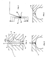
- a generic device used for moulding plastic or elastomeric articles, comprises two elements 1 and 2 respectively, that are alternatively couplable and separable from one another, each being provided with an open hollow zone (3 and 4) so that, in their coupled position, they together delimit a cavity, closed to the outside ambient, having its shape resembling the outer form of the article to be produced.
- the surfaces, that come into reciprocal contact when the mould is closed, are the surfaces a on the element 1, and the surfaces b on the element 2.
- Said surfaces are parallel to each other and they correspond perfectly, apart from the already cited angular errors of flatness.
- At least one of said surfaces for example, the surface b of the element 2, presents an inclination with respect to the bedding plane y of the corresponding facing surface, whose angular value is chosen in ratio to the material that forms the element, so much so that, during the reciprocal approaching movement, between the mould-members, the surfaces a and b come together in contact, firstly along a closed line that delimits the mould cavity, whose intersection, with the drawing plane, is located by point B .
- FIGS. 3 and 4 illustrate a further way of realizing the invention according to which, during the mould closing operation, upon one of the two facing and opposed reciprocally contacting surfaces, there is made, by the removal of material, a projecting part 5 having such dimensions in ratio to the type of material used, that the surface pressure, exercised upon the area c of the projecting part 5, is of a higher value than the threshold of plasticity of the projecting part's material i.e. the material used for the corresponding mould member.
- the projecting part 5 then deforms (just as indicated in FIG. 4), first plastically and thereafter elastically, substantially as in the previously illustrated case. Therefore, the very same considerations which, for that matter, are easily transferable to the example in question, are valid here.
- the area of the surface c of the said projecting part in order to have an elasto-plastic deformation of just the projecting part, the area of the surface c of the said projecting part, once again, will be sensibly less than the area of the remaining portion of surface from where the said projecting part protrudes.
- FIG. 5 illustrates a convenient way for realizing the invention in a tyre mould of the so-called "two-halves” type, i.e. formed by two hollow elements 7 and 8, defined as “shells”, that are provided with an annular cavity opened outwardly, so much so that when reciprocally coupled together they define a toroidal cavity apt for containing the tyre to be vulcanized.
- two-halves i.e. formed by two hollow elements 7 and 8, defined as “shells”
- At least the surface of one of said shells, facing the other shell is a conical surface having its apex v on the mould axis.
- the angular opening of the said surface corresponding here to the angle w , between the axis of symmetry of the mould and the line r on the plane of the cross-section, depends upon the material that is used for realizing the shell. In the case of steel moulds, the angle w will, for convenience sake, not be less than 87° sexagesimals.
- the corresponding surface of the facing shell is shaped conically, either with the same angle or with a diverse angle, with respect to that of the corresponding surface; the important characteristic, according to the invention, having to be, in the case of steel moulds, that the angle z between the two facing surfaces, should not exceed 3° sexagesimals.
- the effective value prevailingly and opportunely used is moreover, in the order of one degree.
- a continuous annular projecting part 9 is made, at least on the surface of one of the two facing shells, in such a position as to delimit by itself, the concave portion of the shell 8.
- Said mould that is much more complex than the previous one, is made of two annular coaxial and opposed elements (10 and 11) substantially concave, defined as 'cheeks', axially and reciprocally shiftable in both senses, apt for moulding the sidewalls of a tyre, and by a plurality of radial elements 12, disposed circumferentially, coaxially to said mould, usually defined as 'sectors', axially shiftable in both senses with respect to one of said cheeks radially shiftable in both senses with respect to both the cheeks, apt for moulding the crown portion of a tyre.
- the phenomenon of 'burrs' is particularly difficult to solve with these moulds.
- the device of the invention has allowed for efficaciously solving the problem, in particular, through a combination of the already illustrated versions, for realizing the invention.
- the cheeks 10 and 11 present their circumferential surfaces facing the sectors, inclined with respect to the facing surfaces, in ratio to the radial direction of the relative shifting between cheeks and sectors; i.e. said surfaces are conical surfaces having their apex on the mould axis, preferably on the same side of the surface, with respect to the diametral plane p of the mould.
- the angle between the two surfaces coinciding with the angular opening v of the cheek surface, when the corresponding surface of the sector is a cylindrical surface coaxial to the mould, has conveniently the value of about 1° sexagesimals; for steel moulds however, the value does not exceed 3° sexagesimals.
- both the corresponding surfaces of the sectors and of the cheeks are conical surfaces, quite conveniently said surfaces will have their apex on the mould axis, both on the same side, for example, as is illustrated in FIG. 8; the difference between the angles w and v however, being contained preferably within a value of 3° sexagesimals.
- the solution of the projecting part finds quite a convenient application.
- the said projecting part 13 realized according to the same already-cited criteria illustrating the FIGS. 3 and 8, becomes developed along the rim of the hollow portion of the sector and instead, it delimits the profile by itself, as is clearly illustrated in FIG. 9; in this quite convenient manner, the ra dial surfaces of the projecting part and of the sector facing the adjacent sectors, can remain as flat surfaces that are hence, easily and economically workable.
- the volume of the part protruding from the lateral surface 14 of the sector 12 will be chosen adequately as a ratio of the mechanical characteristics of the material from which the above-said sector is made.
- the pressure for deforming the projecting part is an exceedingly higher pressure to that of the moulding, the value necessary for guaranteeing the perfect closing of the mould, can even be obtained for very small projecting parts having a height in the order of one tenth of a millimeter, in the case of steel, and however, not exceeding 0.50 mm.
- the Applicant has found it opportune to make, upon one of the two radial surfaces of each sector, a projecting part extended along the entire profile of the cavity, having a height equal to 0.15 mm, and a width (in the radial direction) equal to 3.5 mm.
Landscapes
- Engineering & Computer Science (AREA)
- Mechanical Engineering (AREA)
- Moulds For Moulding Plastics Or The Like (AREA)
- Heating, Cooling, Or Curing Plastics Or The Like In General (AREA)
- Tyre Moulding (AREA)
Applications Claiming Priority (2)
| Application Number | Priority Date | Filing Date | Title |
|---|---|---|---|
| IT2337785 | 1985-12-23 | ||
| IT23377/85A IT1200918B (it) | 1985-12-23 | 1985-12-23 | Miglioramenti agli stampi di vulcanizzazione per pneumatici |
Publications (2)
| Publication Number | Publication Date |
|---|---|
| EP0229985A2 true EP0229985A2 (fr) | 1987-07-29 |
| EP0229985A3 EP0229985A3 (fr) | 1988-05-25 |
Family
ID=11206550
Family Applications (1)
| Application Number | Title | Priority Date | Filing Date |
|---|---|---|---|
| EP86117308A Withdrawn EP0229985A3 (fr) | 1985-12-23 | 1986-12-12 | Moules de vulcanisation de pneus |
Country Status (6)
| Country | Link |
|---|---|
| US (1) | US4772194A (fr) |
| EP (1) | EP0229985A3 (fr) |
| JP (1) | JP2514639B2 (fr) |
| BR (1) | BR8606595A (fr) |
| ES (1) | ES2002235A6 (fr) |
| IT (1) | IT1200918B (fr) |
Cited By (1)
| Publication number | Priority date | Publication date | Assignee | Title |
|---|---|---|---|---|
| EP0726174A1 (fr) * | 1995-02-13 | 1996-08-14 | Sumitomo Rubber Industries Limited | Pneumatique et méthode pour sa fabrication |
Families Citing this family (5)
| Publication number | Priority date | Publication date | Assignee | Title |
|---|---|---|---|---|
| EP0983833B1 (fr) * | 1998-09-03 | 2002-11-27 | Pneu Laurent | Moule pour bandes de roulement plates d'enveloppes de pneumatiques |
| PT983834E (pt) * | 1998-09-03 | 2003-04-30 | Michelin Rech Tech | Molde para bandas de rodagem planas |
| KR100426781B1 (ko) * | 2000-11-23 | 2004-04-13 | 한국타이어 주식회사 | 섹셔널 가류금형 |
| JP6235916B2 (ja) * | 2014-01-21 | 2017-11-22 | 住友ゴム工業株式会社 | タイヤ加硫用金型 |
| FR3045437B1 (fr) * | 2015-12-22 | 2018-02-02 | Compagnie Generale Des Etablissements Michelin | Moule de vulcanisation avec une etancheite renforcee |
Family Cites Families (19)
| Publication number | Priority date | Publication date | Assignee | Title |
|---|---|---|---|---|
| US1513102A (en) * | 1924-10-28 | Method op molding and vulcanizing pneumatic-tire casings | ||
| US1312627A (en) * | 1919-08-12 | John h | ||
| US784874A (en) * | 1904-02-10 | 1905-03-14 | Charles Miller | Mold. |
| FR394990A (fr) * | 1908-10-07 | 1909-02-06 | Claude Marie Gautier | Moule pour la fabrication des bandages pneumatiques |
| GB104870A (en) * | 1916-02-25 | 1918-02-21 | Henri De La Valette | Improvements in the Mounting of the Cams of Interrupters for use in the Ignition of Internal Combustion Engines. |
| US1417509A (en) * | 1921-07-25 | 1922-05-30 | Goodrich Co B F | Vulcanizing mold for tire casings |
| FR836326A (fr) * | 1938-04-07 | 1939-01-16 | Moule pour la fabrication de bandages de véhicules et notamment de voitures d'enfants | |
| JPS4739229Y1 (fr) * | 1968-06-05 | 1972-11-28 | ||
| FR2035649A5 (fr) * | 1969-02-24 | 1970-12-18 | Gen Tire & Rubber Co | |
| US3679345A (en) * | 1970-08-20 | 1972-07-25 | Continental Rubber Works | Flashless compression mold |
| JPS526781A (en) * | 1975-07-07 | 1977-01-19 | Bridgestone Tire Co Ltd | Metal mold for vulcanizing and molding tire |
| US4279854A (en) * | 1979-07-25 | 1981-07-21 | Henry Blaszkowski | Method and apparatus for forming soap bars with an embedded insert |
| JPS58188617A (ja) * | 1982-04-28 | 1983-11-04 | Toyoda Gosei Co Ltd | 簡易金型の製造方法 |
| JPS58175023U (ja) * | 1982-05-17 | 1983-11-22 | アイシン精機株式会社 | 成形型 |
| DE3224278C2 (de) * | 1982-06-28 | 1986-09-25 | Continental Gummi-Werke Ag, 3000 Hannover | Mehrteilige Form zum Herstellen von Gegenständen aus elastomeren Werkstoffen |
| DE3301677C2 (de) * | 1983-01-20 | 1989-03-16 | Bayer Ag, 5090 Leverkusen | Verfahren und Vorrichtung zum Herstellen von Polyurethan-Formteilen |
| US4501715A (en) * | 1983-05-18 | 1985-02-26 | Gilbert Barfield | Mold and method for forming golf balls |
| JPS6030529A (ja) * | 1983-07-28 | 1985-02-16 | Aida Eng Ltd | 段付円筒の穴加工方法 |
| US4655699A (en) * | 1984-03-07 | 1987-04-07 | The Uniroyal Goodrich Tire Company | Reduced flash molding apparatus |
-
1985
- 1985-12-23 IT IT23377/85A patent/IT1200918B/it active
-
1986
- 1986-11-24 US US06/933,897 patent/US4772194A/en not_active Expired - Lifetime
- 1986-12-12 EP EP86117308A patent/EP0229985A3/fr not_active Withdrawn
- 1986-12-23 ES ES8603659A patent/ES2002235A6/es not_active Expired
- 1986-12-23 BR BR8606595A patent/BR8606595A/pt unknown
- 1986-12-23 JP JP61307560A patent/JP2514639B2/ja not_active Expired - Lifetime
Cited By (1)
| Publication number | Priority date | Publication date | Assignee | Title |
|---|---|---|---|---|
| EP0726174A1 (fr) * | 1995-02-13 | 1996-08-14 | Sumitomo Rubber Industries Limited | Pneumatique et méthode pour sa fabrication |
Also Published As
| Publication number | Publication date |
|---|---|
| US4772194A (en) | 1988-09-20 |
| BR8606595A (pt) | 1987-10-20 |
| JP2514639B2 (ja) | 1996-07-10 |
| IT1200918B (it) | 1989-01-27 |
| ES2002235A6 (es) | 1988-07-16 |
| EP0229985A3 (fr) | 1988-05-25 |
| IT8523377A0 (it) | 1985-12-23 |
| JPS62218112A (ja) | 1987-09-25 |
Similar Documents
| Publication | Publication Date | Title |
|---|---|---|
| US4895692A (en) | Mold for the molding and vulcanizing of a rubber tire | |
| US4744741A (en) | Apparatus for the manufacture of composite articles using rotating molds | |
| JPS5842824B2 (ja) | 自動車空気タイヤ用の硬化金型 | |
| KR950013701A (ko) | 타이어 성형틀과 타이어 성형방법 | |
| JP3241867B2 (ja) | タイヤの成形金型と、成形方法 | |
| EP0229985A2 (fr) | Moules de vulcanisation de pneus | |
| US6638054B2 (en) | Injection molding machine for making a worm wheel | |
| US3672807A (en) | Mold construction | |
| KR20130097320A (ko) | 금형 내 구조적 취약부분을 보강하기 위한 슬라이딩 코어를 갖는 이중사출금형 | |
| EP0262863B1 (fr) | Assemblage de moule pour machine à mouler par injection | |
| JP3258188B2 (ja) | 鰓クラッチ状型開き案内手段をもつディスク射出成形金型装置 | |
| KR100421608B1 (ko) | 내측에 언더컷을 갖는 성형품의 사출성형장치 | |
| KR101934359B1 (ko) | 굴곡 튜브 사출 성형 금형 | |
| US6003227A (en) | Process for manufacturing a piston ring | |
| JP4074326B2 (ja) | 樹脂製ジョイントブーツの製造方法 | |
| MY118841A (en) | Mold to shape a ring-shaped body, specially vehicle tires | |
| JPS6319125Y2 (fr) | ||
| JPH04135021A (ja) | バルジ加工用の金属ベローズ成形装置 | |
| JP2517762Y2 (ja) | 射出成形用金型の芯合わせ機構 | |
| JP3096346B2 (ja) | 成形装置とそれを用いた成形品の製造方法 | |
| JPS6189819A (ja) | 成形用金型 | |
| US3608037A (en) | Method for making bearing and sealing means or the like | |
| JP3065376B2 (ja) | 型成形品およびその成形方法並びに成形型 | |
| SU1720870A1 (ru) | Пресс-форма дл изготовлени кольцевых резинотехнических изделий | |
| JPH0514818Y2 (fr) |
Legal Events
| Date | Code | Title | Description |
|---|---|---|---|
| PUAI | Public reference made under article 153(3) epc to a published international application that has entered the european phase |
Free format text: ORIGINAL CODE: 0009012 |
|
| AK | Designated contracting states |
Kind code of ref document: A2 Designated state(s): DE FR GB LU |
|
| PUAL | Search report despatched |
Free format text: ORIGINAL CODE: 0009013 |
|
| AK | Designated contracting states |
Kind code of ref document: A3 Designated state(s): DE FR GB LU |
|
| 16A | New documents despatched to applicant after publication of the search report | ||
| STAA | Information on the status of an ep patent application or granted ep patent |
Free format text: STATUS: THE APPLICATION IS DEEMED TO BE WITHDRAWN |
|
| 18D | Application deemed to be withdrawn |
Effective date: 19881126 |
|
| RIN1 | Information on inventor provided before grant (corrected) |
Inventor name: GALLINOTTI, GIANCARLO Inventor name: PIZZORNO, AUGUSTO |