EP0230205A1 - Centrifugeuse travaillant en continu pour malaxer et centrifuger les masses cuites - Google Patents
Centrifugeuse travaillant en continu pour malaxer et centrifuger les masses cuites Download PDFInfo
- Publication number
- EP0230205A1 EP0230205A1 EP86710003A EP86710003A EP0230205A1 EP 0230205 A1 EP0230205 A1 EP 0230205A1 EP 86710003 A EP86710003 A EP 86710003A EP 86710003 A EP86710003 A EP 86710003A EP 0230205 A1 EP0230205 A1 EP 0230205A1
- Authority
- EP
- European Patent Office
- Prior art keywords
- mashing
- ring
- basket
- liquid
- mash
- Prior art date
- Legal status (The legal status is an assumption and is not a legal conclusion. Google has not performed a legal analysis and makes no representation as to the accuracy of the status listed.)
- Granted
Links
- 238000005360 mashing Methods 0.000 claims abstract description 106
- 239000007788 liquid Substances 0.000 claims abstract description 50
- 238000009826 distribution Methods 0.000 claims abstract description 11
- 239000000463 material Substances 0.000 claims abstract description 5
- 239000013078 crystal Substances 0.000 claims description 38
- 238000009987 spinning Methods 0.000 claims description 10
- 230000001133 acceleration Effects 0.000 claims description 9
- 238000000034 method Methods 0.000 claims description 6
- 229920006395 saturated elastomer Polymers 0.000 claims description 3
- 238000007142 ring opening reaction Methods 0.000 claims description 2
- 238000000926 separation method Methods 0.000 claims description 2
- 239000006188 syrup Substances 0.000 claims description 2
- 235000020357 syrup Nutrition 0.000 claims description 2
- 238000012546 transfer Methods 0.000 claims description 2
- 150000001875 compounds Chemical class 0.000 description 8
- 238000002156 mixing Methods 0.000 description 6
- 230000000694 effects Effects 0.000 description 4
- 239000007787 solid Substances 0.000 description 4
- 239000000945 filler Substances 0.000 description 3
- 239000000203 mixture Substances 0.000 description 3
- 230000002093 peripheral effect Effects 0.000 description 3
- 239000003795 chemical substances by application Substances 0.000 description 2
- 230000002349 favourable effect Effects 0.000 description 2
- 239000000314 lubricant Substances 0.000 description 2
- 230000008569 process Effects 0.000 description 2
- 230000035508 accumulation Effects 0.000 description 1
- 238000009825 accumulation Methods 0.000 description 1
- 230000009471 action Effects 0.000 description 1
- 230000008901 benefit Effects 0.000 description 1
- 230000015572 biosynthetic process Effects 0.000 description 1
- 239000011248 coating agent Substances 0.000 description 1
- 238000000576 coating method Methods 0.000 description 1
- 238000010276 construction Methods 0.000 description 1
- 230000005484 gravity Effects 0.000 description 1
- 238000000265 homogenisation Methods 0.000 description 1
- 230000006872 improvement Effects 0.000 description 1
- 230000003993 interaction Effects 0.000 description 1
- 239000007791 liquid phase Substances 0.000 description 1
- 238000012545 processing Methods 0.000 description 1
- 230000000630 rising effect Effects 0.000 description 1
- 238000012216 screening Methods 0.000 description 1
- 238000003756 stirring Methods 0.000 description 1
- 238000009827 uniform distribution Methods 0.000 description 1
- 238000005406 washing Methods 0.000 description 1
- XLYOFNOQVPJJNP-UHFFFAOYSA-N water Substances O XLYOFNOQVPJJNP-UHFFFAOYSA-N 0.000 description 1
Images

Classifications
-
- C—CHEMISTRY; METALLURGY
- C13—SUGAR INDUSTRY
- C13B—PRODUCTION OF SUCROSE; APPARATUS SPECIALLY ADAPTED THEREFOR
- C13B30/00—Crystallisation; Crystallising apparatus; Separating crystals from mother liquors ; Evaporating or boiling sugar juice
- C13B30/04—Separating crystals from mother liquor
- C13B30/06—Separating crystals from mother liquor by centrifugal force
-
- B—PERFORMING OPERATIONS; TRANSPORTING
- B04—CENTRIFUGAL APPARATUS OR MACHINES FOR CARRYING-OUT PHYSICAL OR CHEMICAL PROCESSES
- B04B—CENTRIFUGES
- B04B3/00—Centrifuges with rotary bowls in which solid particles or bodies become separated by centrifugal force and simultaneous sifting or filtering
Definitions
- the invention relates to a continuously operating centrifuge for mashing and centrifuging sugar filling masses with a sieve basket which is conically widened upwards and which rotates around a vertical axis and which has a feed and distribution pot on a hub projecting upwards into the basket interior and one from the distribution pot to the bottom area of the screen basket protruding downwardly flared acceleration bell, which is designed as a pre-centrifugal drum, and the throwing edge of which is enclosed by a mashing device which surrounds the throwing edge with play and a mashing ring opening out in the area of the ring for the supply of Has mash liquid.
- Centrifuges of the aforementioned type are known (DE-GM 79 34 091), in which a mashing ring is provided which is driven or is stationary at a lower speed than the pre-spinner and which is approximately C-shaped and open towards the discharge edge of the pre-spinner Cross section forms.
- the channels in the area of the mashing ring for the supply of the mashing liquid are formed in the known solution as supply channels rotating with the centrifuge, so that the mashing liquid is thrown into the mashing ring by centrifugal force.
- centrifuges mentioned at the outset have proven themselves in practice for the treatment of fillers of medium purity, in which a single washing process after the preliminary spin is not sufficient to achieve a sufficient separation of the liquid phase from the crystals.
- the invention has for its object to develop a centrifuge of the type described in the introduction so that a safe and uniform promotion the filling mass is reached along the sieve surface of the pre-centrifugal drum and a gentle treatment of the crystal mass during mashing is achieved while maintaining favorable mashing conditions and thereby an improvement in the crystal yield is achieved, namely without a noticeable increase in the energy expenditure for driving the centrifuge.
- the pre-centrifugal drum has a larger opening angle than the strainer basket
- the mashing ring is designed as a co-rotating conically downwardly widened ring with a greater steepness than the strainer basket and the pre-centrifugal drum
- the channels for the mashing liquid are stationary Channels are formed with outflow openings that are provided above the impact zone of the material thrown onto the mashing ring and point in the direction of the mashing ring.
- the filling mass is reliably conveyed along the screen surface of the pre-spinning drum if it has an opening angle between 3 and 14 ° larger than the screen basket.
- the liquid film which forms on the mashing ring also serves as a lubricant when the crystal mass strikes this ring, so that damage caused by the friction of the crystals on the mashing ring is largely prevented and at the same time mixing of these crystals with the different circumferential speeds of the liquid and the crystals the mashing liquid.
- a complete coating of all crystals by the mashing liquid is achieved in a very short way, so that a short residence time of the crystal mass on the mashing ring is sufficient to achieve the desired mashing effect.
- the mashing ring projects beyond the discharge edge of the pre-centrifugal drum towards the basket only over a small part of its height, at most up to half its height. Due to the described steepness of the conical, widening mashing ring, it is sufficient in practice if the mashing ring only protrudes from the throwing edge of the centrifugal drum towards the basket bottom by about one, at most a few cm.
- a preferred embodiment of the invention provides that the mashing ring is enclosed by an accelerating device from at least two further rings arranged coaxially at a distance, one have opposite conicity, form edges at their edges of larger diameter and are axially offset from each other so that they overlap in height.
- the crystalline mass which is obtained during pre-spinning by separating the green runoff, when striking the mashing ring with a film of a mashing liquid continuously applied to the mashing ring sugar-saturated or supersaturated solution of higher purity than the syrup adhering to the crystals is brought into contact and accelerated in the circumferential direction during mashing.
- a mashing liquid of the aforementioned type has the great advantage that the dissolving or dissolving of crystals from the crystal mass brought together with the mashing liquid is prevented.
- the centrifuge described is particularly suitable for the treatment of fillers of medium and higher purity.
- the drawing shows an embodiment of the invention.
- the centrifuge shown only partially in section in FIG. 1 can be driven to rotate about the vertical axis 1. It has a sieve basket, which is denoted overall by 2 and widens upwards, which consists of a solid wall 2a and a sieve 2b held thereon at a distance and which is fixedly connected, for example welded, to the basket base 2c, which is relatively strong in the example shown.
- the screen basket 2 is closed at the top by a relatively solid rim 2d, which is also firmly connected to the basket wall 2a in the example shown.
- the drive shaft 3 connected to a drive, not shown, is held in a stationary position
- Support plate 4 is mounted and carries a hub 5 projecting into the basket interior or, in the example shown, over the basket 2, which carries at its upper end a feed and distribution pot 6, in which the filling compound to be treated is placed in the direction of arrow 7.
- the feed and distribution pot 6 is enclosed by a pre-centrifugal drum 8, which extends conically into the area of the basket base 2c and, like the strainer basket 2, consists of a solid wall 8a and a sieve 8b held thereon, one firmly connected to the wall Bottom 8c with a passage opening for the filling compound and at its extended end facing the basket bottom 2c a solid annular edge 8d.
- the annular edge 8d of the pre-centrifugal drum 8 is enclosed by a mashing ring 9, which in turn is surrounded by two coaxially spaced further rings 10 and 11, which have an opposite conicity and are axially offset from each other so that their height cover up.
- a ring line 12 is arranged which is held stationary and is connected to a supply line 13 for the mashing liquid.
- the In the direction of arrow 7 in the feed and distribution pot 6 transferred filling compound accelerated, with intensive mixing and homogenization taking place at the same time. This effect is promoted by the distributor and drive pins 6a shown in the feed and distributor pot.
- the filling compound emerging via the upper edge of the feed and distribution pot 6 reaches the screen 8b of the pre-spinning drum 8 and migrates from the bottom 8c of the pre-spinning drum in the direction of the annular edge 8d.
- the liquid separated from the filling compound in this centrifuging process enters an annular space 15 of the annular rim 8d and leaves it via drain pipes 16, which are distributed over the circumference of the bottom 2c of the strainer basket.
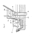
- the centrifuged liquid, which forms the green drain arrives in a collecting space 25, shown schematically in FIG. 2, from which this green drain is removed.
- the crystalline mass remaining on the sieve 8b of the pre-centrifugal drum 8 passes over the ejection edge 17 formed by the annular edge 8d with an umbrella-like or veil-like distribution in the direction of arrow 18 onto the mashing ring 9 and is carried along by the mashing ring and further accelerated in the circumferential direction.
- the outflow openings of the tubular channels 14 are designed pointing in the direction of the mashing ring 9, that is to say they are arranged in such a way that the escaping liquid immediately after its out occurs with the mashing ring 9 and is accelerated by the mashing ring d by appropriate entrainment in the circumferential direction.
- the mashing liquid is distributed in a film-like manner over the lower region of the mashing ring 9 and at the same time flows due to the conicity of the mashing ring 9 in the direction of its lower edge 9a.
- tubular channels 14 for supplying the mash liquid which is shown in solid lines in the direction of the mashing ring 9
- these can also be designed as angled channels which open out almost at a right angle onto the mashing ring 9 according to the dashed illustration 14a in FIG. 2 . It is important that the mashing liquid is applied just above the impact zone of the crystalline filling compound in such a way that a film-like distribution in the direction of the lower edge 9a of the mashing ring 9 is achieved.
- the mashed-in crystalline mass arrives in the bottom edge 9a reproduced example on the acceleration ring 10 rising from the bottom 2c of the screen basket 2, is again thrown off screen-like from the upper edge of this ring and transferred to the further acceleration ring 11, from which the mashed-in crystal mass is again screen-like thrown off and reaches the inside of the screening drum 9.
- the mashed-in crystal mass is thrown out in cooperation with the sieve drum 2 in a known manner, a covering agent in the form of water and / or steam being added to the mass in the lower region of the sieve drum 2.
- the liquid thrown off by the crystal mass, including the opacifying agent, passes through the through openings 19 and 20 of the wall 2a of the strainer basket 2 into a collecting space 21 which is shown schematically in FIG. 2 and which is separated from the collecting space 17 for the green drain.
- the pre-centrifugal drum 8 has a larger opening angle compared to the screen basket 2, which results in a higher speed of movement of the filling material applied in the direction of the lower annular edge 8d. As a result, the conveyed filling mass is reliably conveyed by the pre-spinning drum 8, which cannot be seen during operation.
- the mashing ring 9 is designed to be steeply conical in comparison to the pre-centrifugal drum 8 and the screen basket 2.
- the crystal mass impinging on the mashing ring and the lubricant effect of the crystal mass become different mixing film of the mash liquid reaches a sufficient residence time of the crystalline mass and the mash liquid.
- the short axial path of the mixture of the crystal mass and the mashing liquid prevents the crystals from building up to clumps that are fixed in place on the mashing ring.
- the mashing ring 9 has an L-shaped cross section and is fixedly connected to the bottom 2c of the strainer basket 2 in the region of its lower edge 9a via struts 23 arranged in a radially distributed manner.
- struts 23 arranged in a radially distributed manner.
- the acceleration ring 10 projecting from the bottom 2c of the strainer basket 2 is likewise firmly connected to the bottom 2c, while the further acceleration ring 11 on the outside is fastened, preferably welded, to the outside of the mashing ring 9 via radially arranged struts or a disk 24 formed with openings.
- a largely sugar-saturated or supersaturated solution is expediently used as the mashing liquid so that the dissolving or dissolving of the crystals is avoided as far as possible.
- the amount of the mash liquid suitably corresponds to the amount that was previously separated from the filling compound by the green drain, since the dry matter content of the green drain generally corresponds to that of the mash liquid. If the dry matter contents of the green runoff and the mashing liquid differ very much, the necessary fluidity of the mashed-in crystal mass must be adjusted or generated by changing the ratio of the green runoff to the mashing liquid.
Landscapes
- Chemical & Material Sciences (AREA)
- Crystallography & Structural Chemistry (AREA)
- Life Sciences & Earth Sciences (AREA)
- Biochemistry (AREA)
- Organic Chemistry (AREA)
- Centrifugal Separators (AREA)
Priority Applications (5)
| Application Number | Priority Date | Filing Date | Title |
|---|---|---|---|
| EP86710003A EP0230205B1 (fr) | 1986-01-18 | 1986-01-18 | Centrifugeuse travaillant en continu pour malaxer et centrifuger les masses cuites |
| DE8686710003T DE3665993D1 (en) | 1986-01-18 | 1986-01-18 | Continuously operating centrifuge for mingling and centrifuging masse cuites |
| JP62003433A JPH0636884B2 (ja) | 1986-01-18 | 1987-01-12 | 白下糖を仕込みかつ分離する連続動作遠心分離機およびこの遠心分離機の運転方法 |
| IN25/MAS/87A IN168780B (fr) | 1986-01-18 | 1987-01-16 | |
| US07/183,290 US4802925A (en) | 1986-01-18 | 1988-04-11 | Continuously operable centrifuge for mashing and centrifuging of sugar massecuite |
Applications Claiming Priority (1)
| Application Number | Priority Date | Filing Date | Title |
|---|---|---|---|
| EP86710003A EP0230205B1 (fr) | 1986-01-18 | 1986-01-18 | Centrifugeuse travaillant en continu pour malaxer et centrifuger les masses cuites |
Publications (2)
| Publication Number | Publication Date |
|---|---|
| EP0230205A1 true EP0230205A1 (fr) | 1987-07-29 |
| EP0230205B1 EP0230205B1 (fr) | 1989-10-04 |
Family
ID=8196433
Family Applications (1)
| Application Number | Title | Priority Date | Filing Date |
|---|---|---|---|
| EP86710003A Expired EP0230205B1 (fr) | 1986-01-18 | 1986-01-18 | Centrifugeuse travaillant en continu pour malaxer et centrifuger les masses cuites |
Country Status (5)
| Country | Link |
|---|---|
| US (1) | US4802925A (fr) |
| EP (1) | EP0230205B1 (fr) |
| JP (1) | JPH0636884B2 (fr) |
| DE (1) | DE3665993D1 (fr) |
| IN (1) | IN168780B (fr) |
Cited By (5)
| Publication number | Priority date | Publication date | Assignee | Title |
|---|---|---|---|---|
| DE3828204A1 (de) * | 1988-08-19 | 1990-02-22 | Braunschweigische Masch Bau | Kontinuierlich arbeitende zentrifuge zum einmaischen und abschleudern von zuckerfuellmassen |
| EP0487781A1 (fr) * | 1990-11-30 | 1992-06-03 | Braunschweigische Maschinenbauanstalt AG | Centrifugeuse travaillant en continu pour la centrifugation de masses cuites |
| RU2146658C1 (ru) * | 1998-11-23 | 2000-03-20 | Тумченок Виктор Игнатьевич | Микрофильтр |
| RU2150436C1 (ru) * | 1998-11-23 | 2000-06-10 | Тумченок Виктор Игнатьевич | Биомикрофильтр |
| RU2179959C1 (ru) * | 2000-11-20 | 2002-02-27 | Тумченок Виктор Игнатьевич | Микрофильтр комплекса водоподготовки |
Families Citing this family (1)
| Publication number | Priority date | Publication date | Assignee | Title |
|---|---|---|---|---|
| US5720880A (en) * | 1995-07-03 | 1998-02-24 | California Pellet Mill Company | Sugar centrifugal screen saver |
Citations (2)
| Publication number | Priority date | Publication date | Assignee | Title |
|---|---|---|---|---|
| GB2064351A (en) * | 1979-12-04 | 1981-06-17 | Braunschweigische Masch Bau | Continuously operating centrifugal strainer for sugar massecuites |
| AU544238B2 (en) * | 1981-04-15 | 1985-05-23 | Lehmann Hein A.G. | Apparatus for separating a fillmass or massecuite by centrifugal force |
Family Cites Families (5)
| Publication number | Priority date | Publication date | Assignee | Title |
|---|---|---|---|---|
| DE2333122C2 (de) * | 1973-06-29 | 1985-08-01 | Salzgitter Maschinen Und Anlagen Ag, 3320 Salzgitter | Vorrichtung zur Betätigung eines Verschlußkörpers einer Zentrifuge |
| FR2245415B1 (fr) * | 1973-10-02 | 1978-09-29 | Fives Cail Babcock | |
| US3970470A (en) * | 1974-10-18 | 1976-07-20 | Hein, Lehmann A.G. | Centrifuge |
| DE2936659A1 (de) * | 1979-09-11 | 1981-03-19 | Braunschweigische Maschinenbauanstalt AG, 3300 Braunschweig | Kontinuierlich arbeitende zuckerzentrifuge |
| JP5854859B2 (ja) | 2012-01-27 | 2016-02-09 | 日東電工株式会社 | 汚染防止方法 |
-
1986
- 1986-01-18 EP EP86710003A patent/EP0230205B1/fr not_active Expired
- 1986-01-18 DE DE8686710003T patent/DE3665993D1/de not_active Expired
-
1987
- 1987-01-12 JP JP62003433A patent/JPH0636884B2/ja not_active Expired - Lifetime
- 1987-01-16 IN IN25/MAS/87A patent/IN168780B/en unknown
-
1988
- 1988-04-11 US US07/183,290 patent/US4802925A/en not_active Expired - Fee Related
Patent Citations (2)
| Publication number | Priority date | Publication date | Assignee | Title |
|---|---|---|---|---|
| GB2064351A (en) * | 1979-12-04 | 1981-06-17 | Braunschweigische Masch Bau | Continuously operating centrifugal strainer for sugar massecuites |
| AU544238B2 (en) * | 1981-04-15 | 1985-05-23 | Lehmann Hein A.G. | Apparatus for separating a fillmass or massecuite by centrifugal force |
Cited By (5)
| Publication number | Priority date | Publication date | Assignee | Title |
|---|---|---|---|---|
| DE3828204A1 (de) * | 1988-08-19 | 1990-02-22 | Braunschweigische Masch Bau | Kontinuierlich arbeitende zentrifuge zum einmaischen und abschleudern von zuckerfuellmassen |
| EP0487781A1 (fr) * | 1990-11-30 | 1992-06-03 | Braunschweigische Maschinenbauanstalt AG | Centrifugeuse travaillant en continu pour la centrifugation de masses cuites |
| RU2146658C1 (ru) * | 1998-11-23 | 2000-03-20 | Тумченок Виктор Игнатьевич | Микрофильтр |
| RU2150436C1 (ru) * | 1998-11-23 | 2000-06-10 | Тумченок Виктор Игнатьевич | Биомикрофильтр |
| RU2179959C1 (ru) * | 2000-11-20 | 2002-02-27 | Тумченок Виктор Игнатьевич | Микрофильтр комплекса водоподготовки |
Also Published As
| Publication number | Publication date |
|---|---|
| US4802925A (en) | 1989-02-07 |
| IN168780B (fr) | 1991-06-01 |
| EP0230205B1 (fr) | 1989-10-04 |
| JPH0636884B2 (ja) | 1994-05-18 |
| JPS62216656A (ja) | 1987-09-24 |
| DE3665993D1 (en) | 1989-11-09 |
Similar Documents
| Publication | Publication Date | Title |
|---|---|---|
| DE2750696A1 (de) | Mehrstufiges verfahren und vorrichtung zum aufbringen eines spruehfaehigen mittels auf ein material aus losen granulat-, schuppen-, span- oder faserteilchen | |
| DE2207663C3 (de) | Kontinuierlich arbeitende Zuckerzentrifuge | |
| DE2550496B2 (de) | Verfahren und Zentrifuge zum Abschleudern und Wiederauflösen von Zucker | |
| CH622341A5 (fr) | ||
| EP0230205B1 (fr) | Centrifugeuse travaillant en continu pour malaxer et centrifuger les masses cuites | |
| DE3415519C2 (fr) | ||
| DE2834491C2 (de) | Siebzentrifuge mit gekrümmten Siebtaschen | |
| DE2025828B2 (de) | Kontinuierlich arbeitende zentrifuge | |
| DE2608911A1 (de) | Kontinuierlich arbeitende zuckerzentrifuge, insbesondere fuer mittelprodukt und/oder weisszuckerfuellmassen | |
| EP0163112B1 (fr) | Procédé et dispositif pour la séparation centrifuge de mélanges de minéraux à grains fins | |
| EP0487780A1 (fr) | Centrifugeuse travaillant en continu pour la centrifugation de masses cuites | |
| DE3615224C2 (fr) | ||
| DE2328830A1 (de) | Zentrifuge, insbesondere zuckerzentrifuge | |
| DE2803160A1 (de) | Kontinuierlich arbeitende zentrifuge | |
| EP2429711B1 (fr) | Centrifugeuse à fonctionnement continu | |
| DE2930312C2 (de) | Siebzentrifuge | |
| DE3828204C2 (fr) | ||
| EP0263285B1 (fr) | Centrifugeuse à sucre travaillant en continu | |
| EP0455964B1 (fr) | Centrifugeuse | |
| DE2246155A1 (de) | Zentrifuge mit kontinuierlicher entleerung zum filtrieren von materialien beliebiger art, insbesondere von faserstoffen | |
| DE951140C (de) | Siebzentrifuge zum Entfernen von Fluessigkeiten aus Dickstoffen | |
| DE505249C (de) | Ununterbrochen wirkende Schleuder fuer Rohzucker | |
| DE529610C (de) | Kegelsiebschleuder zum Entwaessern von Kohle u. dgl. mit im Innern des Siebkegels ringfoermig angeordneten Ablenkrippen | |
| DE2306302B2 (de) | Zentrifugenrotor mit um seine Achse angeordneten schaufelartig gekrümmten Siebflächen | |
| DE19809422A1 (de) | Siebverfahren und -vorrichtung |
Legal Events
| Date | Code | Title | Description |
|---|---|---|---|
| PUAI | Public reference made under article 153(3) epc to a published international application that has entered the european phase |
Free format text: ORIGINAL CODE: 0009012 |
|
| AK | Designated contracting states |
Kind code of ref document: A1 Designated state(s): DE FR GB IT SE |
|
| 17P | Request for examination filed |
Effective date: 19870903 |
|
| 17Q | First examination report despatched |
Effective date: 19881028 |
|
| GRAA | (expected) grant |
Free format text: ORIGINAL CODE: 0009210 |
|
| AK | Designated contracting states |
Kind code of ref document: B1 Designated state(s): DE FR GB IT SE |
|
| REF | Corresponds to: |
Ref document number: 3665993 Country of ref document: DE Date of ref document: 19891109 |
|
| GBT | Gb: translation of ep patent filed (gb section 77(6)(a)/1977) | ||
| ET | Fr: translation filed | ||
| PGFP | Annual fee paid to national office [announced via postgrant information from national office to epo] |
Ref country code: SE Payment date: 19891211 Year of fee payment: 5 |
|
| ITF | It: translation for a ep patent filed | ||
| PLBE | No opposition filed within time limit |
Free format text: ORIGINAL CODE: 0009261 |
|
| STAA | Information on the status of an ep patent application or granted ep patent |
Free format text: STATUS: NO OPPOSITION FILED WITHIN TIME LIMIT |
|
| 26N | No opposition filed | ||
| PG25 | Lapsed in a contracting state [announced via postgrant information from national office to epo] |
Ref country code: SE Effective date: 19910119 |
|
| ITTA | It: last paid annual fee | ||
| EUG | Se: european patent has lapsed |
Ref document number: 86710003.4 Effective date: 19910910 |
|
| PGFP | Annual fee paid to national office [announced via postgrant information from national office to epo] |
Ref country code: FR Payment date: 19961129 Year of fee payment: 12 |
|
| PGFP | Annual fee paid to national office [announced via postgrant information from national office to epo] |
Ref country code: GB Payment date: 19970109 Year of fee payment: 12 |
|
| PGFP | Annual fee paid to national office [announced via postgrant information from national office to epo] |
Ref country code: DE Payment date: 19970115 Year of fee payment: 12 |
|
| PG25 | Lapsed in a contracting state [announced via postgrant information from national office to epo] |
Ref country code: GB Free format text: LAPSE BECAUSE OF NON-PAYMENT OF DUE FEES Effective date: 19980118 |
|
| PG25 | Lapsed in a contracting state [announced via postgrant information from national office to epo] |
Ref country code: FR Free format text: THE PATENT HAS BEEN ANNULLED BY A DECISION OF A NATIONAL AUTHORITY Effective date: 19980131 |
|
| GBPC | Gb: european patent ceased through non-payment of renewal fee |
Effective date: 19980118 |
|
| PG25 | Lapsed in a contracting state [announced via postgrant information from national office to epo] |
Ref country code: DE Free format text: LAPSE BECAUSE OF NON-PAYMENT OF DUE FEES Effective date: 19981001 |
|
| REG | Reference to a national code |
Ref country code: FR Ref legal event code: ST |
|
| PG25 | Lapsed in a contracting state [announced via postgrant information from national office to epo] |
Ref country code: IT Free format text: LAPSE BECAUSE OF NON-PAYMENT OF DUE FEES;WARNING: LAPSES OF ITALIAN PATENTS WITH EFFECTIVE DATE BEFORE 2007 MAY HAVE OCCURRED AT ANY TIME BEFORE 2007. THE CORRECT EFFECTIVE DATE MAY BE DIFFERENT FROM THE ONE RECORDED. Effective date: 20050118 |