EP0487781A1 - Centrifugeuse travaillant en continu pour la centrifugation de masses cuites - Google Patents
Centrifugeuse travaillant en continu pour la centrifugation de masses cuites Download PDFInfo
- Publication number
- EP0487781A1 EP0487781A1 EP90122965A EP90122965A EP0487781A1 EP 0487781 A1 EP0487781 A1 EP 0487781A1 EP 90122965 A EP90122965 A EP 90122965A EP 90122965 A EP90122965 A EP 90122965A EP 0487781 A1 EP0487781 A1 EP 0487781A1
- Authority
- EP
- European Patent Office
- Prior art keywords
- product distributor
- distributor
- centrifuge according
- sugar
- basket
- Prior art date
- Legal status (The legal status is an assumption and is not a legal conclusion. Google has not performed a legal analysis and makes no representation as to the accuracy of the status listed.)
- Withdrawn
Links
- 230000002093 peripheral effect Effects 0.000 claims description 3
- 150000001875 compounds Chemical class 0.000 description 13
- 238000009826 distribution Methods 0.000 description 9
- 239000000945 filler Substances 0.000 description 6
- 239000002245 particle Substances 0.000 description 5
- 239000007787 solid Substances 0.000 description 3
- 230000000694 effects Effects 0.000 description 2
- 238000004519 manufacturing process Methods 0.000 description 2
- 238000009987 spinning Methods 0.000 description 2
- XLYOFNOQVPJJNP-UHFFFAOYSA-N water Substances O XLYOFNOQVPJJNP-UHFFFAOYSA-N 0.000 description 2
- 230000001133 acceleration Effects 0.000 description 1
- 230000035508 accumulation Effects 0.000 description 1
- 238000009825 accumulation Methods 0.000 description 1
- 230000015572 biosynthetic process Effects 0.000 description 1
- 238000010276 construction Methods 0.000 description 1
- 230000005484 gravity Effects 0.000 description 1
- 238000005360 mashing Methods 0.000 description 1
- 239000000463 material Substances 0.000 description 1
- 238000000034 method Methods 0.000 description 1
- 230000000717 retained effect Effects 0.000 description 1
Images

Classifications
-
- C—CHEMISTRY; METALLURGY
- C13—SUGAR INDUSTRY
- C13B—PRODUCTION OF SUCROSE; APPARATUS SPECIALLY ADAPTED THEREFOR
- C13B30/00—Crystallisation; Crystallising apparatus; Separating crystals from mother liquors ; Evaporating or boiling sugar juice
- C13B30/04—Separating crystals from mother liquor
- C13B30/06—Separating crystals from mother liquor by centrifugal force
-
- B—PERFORMING OPERATIONS; TRANSPORTING
- B04—CENTRIFUGAL APPARATUS OR MACHINES FOR CARRYING-OUT PHYSICAL OR CHEMICAL PROCESSES
- B04B—CENTRIFUGES
- B04B3/00—Centrifuges with rotary bowls in which solid particles or bodies become separated by centrifugal force and simultaneous sifting or filtering
Definitions
- the invention relates to a continuously operating centrifuge for centrifuging sugar filling masses with a sieve basket which is flared upwards and which rotates about a vertical axis, a product distributor which is flared downwards and which extends into the bottom region of the sieve basket and which is essentially coaxial to the sieve basket, below forms a discharge edge and rotates about the same vertical axis as the strainer basket, and a distribution pot provided inside and in the upper area of the product distributor as a feed device for the sugar filling masses in the axis area of the centrifuge.
- centrifuges are known for example from DE 22 07 663 C3 or DE 38 28 204 C2.
- the sugar filling mass is first placed in the distribution pot as a feed device. This is located in the axis area of the centrifuge and should ensure that the sugar filling mass is distributed as evenly as possible for further processing in the centrifuge.
- the filling compound is carried along in the distribution pot by adhesion to its wall and gradually accelerated to the peripheral speed of the wall.
- the filling mass is distributed over the circumference of the distribution pot and is thrown off over the upper edge of the distribution pot if the filling mass continues to flow.
- the filling compound hits the inside surface of the product distributor, which is also known as the acceleration bell or pre-spinning drum can be.
- the filler can be supplied with steam or deck water from the appropriate feed lines.
- the well-known product distributors themselves are drum-like and expand slightly conically downwards. They form a discharge rim at the bottom, from which the sugar filling masses reaching there are thrown outwards into the actual sieve basket, which is flared upwards and rotates about the same vertical axis.
- a constant problem is that the filling compound supplied to the distributor pot is distributed unevenly with increasing viscosity and forms a layer of different thickness on the inner surface of the product distributor.
- upstanding distributor rods are arranged in order to first mechanically divide the filler mass strand before the filler mass reaches the inner surface of the distributor pot, strip-shaped inhomogeneities of the filler mass arise which continue through the product distributor to the sieve surface of the drum.
- the object of the invention is therefore to further improve the uniformity of the distribution of the sugar filling masses in the continuously operating centrifuges.
- a stationary baffle is arranged radially around the discharge edge of the product distributor with play to the product distributor and to the strainer basket in such a way that it is struck by sugar filling masses thrown off the discharge edge.
- the distribution of sugar filling compounds is significantly improved by the invention, specifically in the case of highly viscous sugar filling compounds.
- the sugar filling masses that reach the lower discharge edge of the product distributor are not thrown directly onto the sieve basket when they are spun, but rather hit a stationary baffle. However, they themselves have a considerable tangential component during the spin-off, which continues as a relative movement in the circumferential direction even when they strike the impact surface. However, as a result, any accumulations and lumps that are present are smeared over a larger angular range, and a balance of relatively thick to relatively thin sugar filling mass layers occurs.
- the stationary baffles naturally slow down the impinging sugar filling masses, which drip from these baffles in the direction of the sieve basket base due to gravity. There they are again taken along and accelerated because the sieve basket bottom rotates with the sieve basket wall. From the bottom, the sugar filling masses then get back onto the sieve basket wall due to their centrifugal force and take the path known from the prior art
- the already prepared filling compound hits this stationary impact surface immediately after being spun off from the product distributor and before the important further processing on the screen basket.
- Non-uniformities in the layer thickness caused by manufacturing tolerances or connecting webs are largely eliminated.
- the formation of lumps of sugar is prevented.
- the product distributor is surrounded by a stationary bell which surrounds it with all-round play, is flared downwards and projects above the product distributor, and that the baffle surface is formed by the lower edge of the stationary bell.
- a baffle formed in this way is particularly easy to provide in the centrifuge because it can be used from above as a continuous, relatively stable and torsion-resistant part.
- a steam supply can be provided between the inner wall of the bell and the outer wall of the product distributor, which at the same time heats the sugar filling compound passing through the product distributor.
- peripheral wall of the product distributor has a plurality of ring elements which overlap in the axial direction while leaving an annular gap. Then the supplied steam can reach the interior of the product distributor via the annular gaps.
- the construction required to form the baffle surface can be used for a number of other advantages.
- the impact surface itself is preferably formed identically all around in profile. This favors an equalization of the filling compound layer over the entire circumferential area.
- the impact surface itself can be designed differently; under certain circumstances it is even advantageous to provide the baffle in an exchangeable manner in order to make adjustments to its flowability, viscosity or other external circumstances depending on the consistency of the sugar filling compound.
- the baffle surface is a conically widening surface.
- the baffle is a continuation of the conical bell shape; combined with the design with the ring elements, an additional, but in contrast to the other, stationary ring element would be formed.
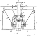
- the centrifuge shown has a stationary frame 10 with a base 11, side walls 12, a cover 13 above the actual strainer basket 20 and a filling funnel 14.
- the sugar filling mass falls into the distribution pot 30 through the filling funnel 14 and a likewise fixed shaft 15.
- the screen basket 20, the distributor pot 30 and a product distributor 40 rotate about a common vertical axis 16.
- the distributor pot 30 has a flat bottom 31 and a cylindrical wall 32.
- the product distributor 40 has 3 ring elements, 41, 42, 43, each of which extends conically downwards, but is otherwise cylinder-symmetrical.
- An annular gap 44 or 45 is formed between the ring elements 41 and 42 or the ring elements 42 and 43.
- the ring elements 41, 42, 43 can be fastened to one another by means of individual webs.
- the uppermost ring element 41 is closed at the top, but allows the shaft 15 to pass into the distribution pot 30 in the region near the axis for filling the sugar filling compound.
- the fastening of the rods 34 is also arranged.
- the ring elements 41, 42, 43 of the product distributor 40 are surrounded with a play on all sides by a stationary bell 50 which is flared downwards.
- This bell 50 is fastened to the cover 13 by means of a holding device 51.
- the bell 50 is cylindrically symmetrical to the axis 16, so that the play between the bell 50 and the ring elements of the product distributor 40 is cylindrically symmetrical.
- a steam supply 52 leads into the game, with which steam (not shown) enters the area between the product distributor 40 and the bell 50 from the outside can. This steam then passes through the annular gaps 44, 45 into the interior of the ring elements 41, 42, 43 and flows through the sugar filling masses located there.
- the sugar filling mass passes from one ring element 41, 42, 43 to the next lower one.
- the sugar filling mass is thrown outwards from the discharge edge of the lowermost ring element 43.
- the stationary bell 50 extends further downward than the lower edge of the lowermost ring element 43 of the product distributor 40.
- the bell 50 is equipped there with a relatively solid rim that forms an impact surface 53.
- the particles After extensive braking, the particles reach the basket bottom 23 of the sieve basket 20 after being largely braked down. As this rotates again, they are carried along, accelerated and finally migrate to a sieve which is firmly connected to the basket bottom and on which they settle due to the centrifugal force move up.
- the sieve basket 20 is closed at the top by a relatively solid discharge rim 22, from which the sugar particles are thrown outwards, collected there and processed (not shown).
- a mashing device can be provided in the area of the impact surface 53.
- the baffle surface 53 is of identical design all round. 2 and 3 show how the area of the baffle 53 can be designed in detail.
- a section of the strainer basket 20 with the basket bottom is shown in each case, which rotate with one another about the axis 16 (this in FIG. 1).
- the product distributor 40 rotates about the same axis at the same or a different speed, the lowest region of which can be seen with the discharge edge.
- the product distributor 40 is surrounded by a bell 50, the bottom edge of which is designed as an impact surface 53.
- the bell 50 does not rotate, rather it is fixed. In one embodiment it can be provided that this bell is rotated in the opposite direction to the product distributor or at a different speed than the product distributor in its direction.
- baffle 53 itself is different in FIGS. 2 and 3. In Fig. 2 it is opened conically downwards. This creates a cone section.
- baffle surface 53 which is open in a parabolic manner downwards is provided.
Landscapes
- Chemical & Material Sciences (AREA)
- Crystallography & Structural Chemistry (AREA)
- Life Sciences & Earth Sciences (AREA)
- Biochemistry (AREA)
- Organic Chemistry (AREA)
- Centrifugal Separators (AREA)
Priority Applications (1)
| Application Number | Priority Date | Filing Date | Title |
|---|---|---|---|
| EP90122965A EP0487781A1 (fr) | 1990-11-30 | 1990-11-30 | Centrifugeuse travaillant en continu pour la centrifugation de masses cuites |
Applications Claiming Priority (1)
| Application Number | Priority Date | Filing Date | Title |
|---|---|---|---|
| EP90122965A EP0487781A1 (fr) | 1990-11-30 | 1990-11-30 | Centrifugeuse travaillant en continu pour la centrifugation de masses cuites |
Publications (1)
| Publication Number | Publication Date |
|---|---|
| EP0487781A1 true EP0487781A1 (fr) | 1992-06-03 |
Family
ID=8204775
Family Applications (1)
| Application Number | Title | Priority Date | Filing Date |
|---|---|---|---|
| EP90122965A Withdrawn EP0487781A1 (fr) | 1990-11-30 | 1990-11-30 | Centrifugeuse travaillant en continu pour la centrifugation de masses cuites |
Country Status (1)
| Country | Link |
|---|---|
| EP (1) | EP0487781A1 (fr) |
Cited By (1)
| Publication number | Priority date | Publication date | Assignee | Title |
|---|---|---|---|---|
| CN111346419A (zh) * | 2018-12-20 | 2020-06-30 | 广西盛誉糖机制造有限责任公司 | 一种离心机用中心密封进料装置 |
Citations (5)
| Publication number | Priority date | Publication date | Assignee | Title |
|---|---|---|---|---|
| DE1120379B (de) * | 1959-06-13 | 1961-12-21 | Julius Von Roetel | Kontinuierlich arbeitende Siebzentrifuge |
| DE2631178A1 (de) * | 1976-07-10 | 1978-01-19 | Buckau Wolf Maschf R | Kontinuierlich arbeitende siebzentrifuge, insbesondere zuckerzentrifuge |
| GB2064351A (en) * | 1979-12-04 | 1981-06-17 | Braunschweigische Masch Bau | Continuously operating centrifugal strainer for sugar massecuites |
| EP0152855A2 (fr) * | 1984-02-17 | 1985-08-28 | Hein, Lehmann Aktiengesellschaft | Centrifuge à fonctionnement continu |
| EP0230205A1 (fr) * | 1986-01-18 | 1987-07-29 | Braunschweigische Maschinenbauanstalt AG | Centrifugeuse travaillant en continu pour malaxer et centrifuger les masses cuites |
-
1990
- 1990-11-30 EP EP90122965A patent/EP0487781A1/fr not_active Withdrawn
Patent Citations (5)
| Publication number | Priority date | Publication date | Assignee | Title |
|---|---|---|---|---|
| DE1120379B (de) * | 1959-06-13 | 1961-12-21 | Julius Von Roetel | Kontinuierlich arbeitende Siebzentrifuge |
| DE2631178A1 (de) * | 1976-07-10 | 1978-01-19 | Buckau Wolf Maschf R | Kontinuierlich arbeitende siebzentrifuge, insbesondere zuckerzentrifuge |
| GB2064351A (en) * | 1979-12-04 | 1981-06-17 | Braunschweigische Masch Bau | Continuously operating centrifugal strainer for sugar massecuites |
| EP0152855A2 (fr) * | 1984-02-17 | 1985-08-28 | Hein, Lehmann Aktiengesellschaft | Centrifuge à fonctionnement continu |
| EP0230205A1 (fr) * | 1986-01-18 | 1987-07-29 | Braunschweigische Maschinenbauanstalt AG | Centrifugeuse travaillant en continu pour malaxer et centrifuger les masses cuites |
Cited By (1)
| Publication number | Priority date | Publication date | Assignee | Title |
|---|---|---|---|---|
| CN111346419A (zh) * | 2018-12-20 | 2020-06-30 | 广西盛誉糖机制造有限责任公司 | 一种离心机用中心密封进料装置 |
Similar Documents
| Publication | Publication Date | Title |
|---|---|---|
| EP0487780B1 (fr) | Centrifugeuse travaillant en continu pour la centrifugation de masses cuites | |
| DE2608911A1 (de) | Kontinuierlich arbeitende zuckerzentrifuge, insbesondere fuer mittelprodukt und/oder weisszuckerfuellmassen | |
| DE3415519A1 (de) | Kontinuierlich arbeitende siebzentrifuge | |
| EP2429711B1 (fr) | Centrifugeuse à fonctionnement continu | |
| DE2328830A1 (de) | Zentrifuge, insbesondere zuckerzentrifuge | |
| EP0230205B1 (fr) | Centrifugeuse travaillant en continu pour malaxer et centrifuger les masses cuites | |
| DE3615224C3 (de) | Kontinuierlich arbeitende Zuckerzentrifuge | |
| EP0257270B1 (fr) | Centrifugeuse à sucre à marche continue | |
| DE2306302C3 (de) | Zentrifugenrotor mit um seine Achse angeordneten schaufelartig gekrümmten Siebflächen | |
| DE2948691A1 (de) | Kontinuierlich arbeitende zentrifuge zum einmaischen und abschleudern von zuckerfuellmassen | |
| DE2841725C2 (de) | Vorrichtung zum Beschicken einer kontinuierlich arbeitenden Zentrifuge | |
| DE529610C (de) | Kegelsiebschleuder zum Entwaessern von Kohle u. dgl. mit im Innern des Siebkegels ringfoermig angeordneten Ablenkrippen | |
| EP0455964B1 (fr) | Centrifugeuse | |
| EP0263285B1 (fr) | Centrifugeuse à sucre travaillant en continu | |
| DE1026692B (de) | Schneckenzentrifuge zum kontinuierlichen Trennen von mehrkomponentigen, einen festen Schwebestoff enthaltenden Schleuderguetern | |
| DE1288988B (de) | Kontinuierlich arbeitende Siebzentrifuge, insbesondere Zuckerzentrifuge | |
| DE1507653A1 (de) | Ruehrwerksmuehle zum Mahlen und Dispergieren von Feststoffteilen in fluessigen Medien | |
| DE2930312A1 (de) | Siebzentrifuge | |
| DE1961505C2 (de) | Vorrichtung zur Vermeidung von Verkrustungen abgeschleuderten Zuckers im Zuckerauffangraum einer kontinuierlich arbeitenden Zuckerzentrifuge | |
| DE505249C (de) | Ununterbrochen wirkende Schleuder fuer Rohzucker | |
| EP0692311A1 (fr) | Centrifugeuse travaillant en continu pour la centrifugation de masses cuites | |
| DE712917C (de) | Vorrichtung zum Erzeugen von Fasern aus Glas oder anderen in der Hitze plastischen Massen durch Schleudern | |
| DE2631178A1 (de) | Kontinuierlich arbeitende siebzentrifuge, insbesondere zuckerzentrifuge | |
| DE810731C (de) | Vorrichtung zum Abschleudern von Schleudergut durch Siebe | |
| DE3828204A1 (de) | Kontinuierlich arbeitende zentrifuge zum einmaischen und abschleudern von zuckerfuellmassen |
Legal Events
| Date | Code | Title | Description |
|---|---|---|---|
| PUAI | Public reference made under article 153(3) epc to a published international application that has entered the european phase |
Free format text: ORIGINAL CODE: 0009012 |
|
| AK | Designated contracting states |
Kind code of ref document: A1 Designated state(s): DE FR GB IT SE |
|
| STAA | Information on the status of an ep patent application or granted ep patent |
Free format text: STATUS: THE APPLICATION IS DEEMED TO BE WITHDRAWN |
|
| 18D | Application deemed to be withdrawn |
Effective date: 19921204 |