EP0230275A2 - Appareil de lecture/écriture pour carte à mémoire optique - Google Patents
Appareil de lecture/écriture pour carte à mémoire optique Download PDFInfo
- Publication number
- EP0230275A2 EP0230275A2 EP87100462A EP87100462A EP0230275A2 EP 0230275 A2 EP0230275 A2 EP 0230275A2 EP 87100462 A EP87100462 A EP 87100462A EP 87100462 A EP87100462 A EP 87100462A EP 0230275 A2 EP0230275 A2 EP 0230275A2
- Authority
- EP
- European Patent Office
- Prior art keywords
- carriage
- card
- memory card
- reading
- optical memory
- Prior art date
- Legal status (The legal status is an assumption and is not a legal conclusion. Google has not performed a legal analysis and makes no representation as to the accuracy of the status listed.)
- Withdrawn
Links
Images




Classifications
-
- G—PHYSICS
- G11—INFORMATION STORAGE
- G11B—INFORMATION STORAGE BASED ON RELATIVE MOVEMENT BETWEEN RECORD CARRIER AND TRANSDUCER
- G11B19/00—Driving, starting, stopping record carriers not specifically of filamentary or web form, or of supports therefor; Control thereof; Control of operating function ; Driving both disc and head
- G11B19/20—Driving; Starting; Stopping; Control thereof
-
- G—PHYSICS
- G06—COMPUTING OR CALCULATING; COUNTING
- G06K—GRAPHICAL DATA READING; PRESENTATION OF DATA; RECORD CARRIERS; HANDLING RECORD CARRIERS
- G06K13/00—Conveying record carriers from one station to another, e.g. from stack to punching mechanism
- G06K13/02—Conveying record carriers from one station to another, e.g. from stack to punching mechanism the record carrier having longitudinal dimension comparable with transverse dimension, e.g. punched card
- G06K13/08—Feeding or discharging cards
-
- G—PHYSICS
- G06—COMPUTING OR CALCULATING; COUNTING
- G06K—GRAPHICAL DATA READING; PRESENTATION OF DATA; RECORD CARRIERS; HANDLING RECORD CARRIERS
- G06K13/00—Conveying record carriers from one station to another, e.g. from stack to punching mechanism
- G06K13/02—Conveying record carriers from one station to another, e.g. from stack to punching mechanism the record carrier having longitudinal dimension comparable with transverse dimension, e.g. punched card
- G06K13/08—Feeding or discharging cards
- G06K13/0806—Feeding or discharging cards using an arrangement for ejection of an inserted card
- G06K13/0831—Feeding or discharging cards using an arrangement for ejection of an inserted card the ejection arrangement comprising a slide, carriage or drawer
-
- G—PHYSICS
- G06—COMPUTING OR CALCULATING; COUNTING
- G06K—GRAPHICAL DATA READING; PRESENTATION OF DATA; RECORD CARRIERS; HANDLING RECORD CARRIERS
- G06K13/00—Conveying record carriers from one station to another, e.g. from stack to punching mechanism
- G06K13/02—Conveying record carriers from one station to another, e.g. from stack to punching mechanism the record carrier having longitudinal dimension comparable with transverse dimension, e.g. punched card
- G06K13/08—Feeding or discharging cards
- G06K13/0868—Feeding or discharging cards using an arrangement for keeping the feeding or insertion slot of the card station clean of dirt, or to avoid feeding of foreign or unwanted objects into the slot
- G06K13/0893—Feeding or discharging cards using an arrangement for keeping the feeding or insertion slot of the card station clean of dirt, or to avoid feeding of foreign or unwanted objects into the slot the arrangement comprising means for cleaning the card upon insertion
-
- G—PHYSICS
- G06—COMPUTING OR CALCULATING; COUNTING
- G06K—GRAPHICAL DATA READING; PRESENTATION OF DATA; RECORD CARRIERS; HANDLING RECORD CARRIERS
- G06K7/00—Methods or arrangements for sensing record carriers, e.g. for reading patterns
- G06K7/10—Methods or arrangements for sensing record carriers, e.g. for reading patterns by electromagnetic radiation, e.g. optical sensing; by corpuscular radiation
- G06K7/10544—Methods or arrangements for sensing record carriers, e.g. for reading patterns by electromagnetic radiation, e.g. optical sensing; by corpuscular radiation by scanning of the records by radiation in the optical part of the electromagnetic spectrum
- G06K7/10821—Methods or arrangements for sensing record carriers, e.g. for reading patterns by electromagnetic radiation, e.g. optical sensing; by corpuscular radiation by scanning of the records by radiation in the optical part of the electromagnetic spectrum further details of bar or optical code scanning devices
- G06K7/10831—Arrangement of optical elements, e.g. lenses, mirrors, prisms
-
- G—PHYSICS
- G11—INFORMATION STORAGE
- G11B—INFORMATION STORAGE BASED ON RELATIVE MOVEMENT BETWEEN RECORD CARRIER AND TRANSDUCER
- G11B23/00—Record carriers not specific to the method of recording or reproducing; Accessories, e.g. containers, specially adapted for co-operation with the recording or reproducing apparatus ; Intermediate mediums; Apparatus or processes specially adapted for their manufacture
- G11B23/50—Reconditioning of record carriers; Cleaning of record carriers ; Carrying-off electrostatic charges
- G11B23/505—Reconditioning of record carriers; Cleaning of record carriers ; Carrying-off electrostatic charges of disk carriers
-
- G—PHYSICS
- G11—INFORMATION STORAGE
- G11B—INFORMATION STORAGE BASED ON RELATIVE MOVEMENT BETWEEN RECORD CARRIER AND TRANSDUCER
- G11B7/00—Recording or reproducing by optical means, e.g. recording using a thermal beam of optical radiation by modifying optical properties or the physical structure, reproducing using an optical beam at lower power by sensing optical properties; Record carriers therefor
- G11B7/002—Recording, reproducing or erasing systems characterised by the shape or form of the carrier
- G11B7/0033—Recording, reproducing or erasing systems characterised by the shape or form of the carrier with cards or other card-like flat carriers, e.g. flat sheets of optical film
Definitions
- This invention relates to a reader/writer apparatus for an optical memory card which reads and/or writes data from and/or into the optical memory card, and more particularly to a reader/writer apparatus for an optical memory card provided with a card holder for holding and transporting the optical memory card.
- a holder holding an optical memory card is moved linearly in a certain direction, for example, in a longitudinal direction (assumed as an X-axis) of the optical memory card and an optical system of a reading/writing head is moved in a direction (assumed as Y-axis) perpedicular to said longitudinal direction for carrying out reading/writing scanning.
- a Y-axis moving mechanism including a guide frame and a drive and a reading/writing head including an optical system and an adjusting drive are mounted on a holder holding an optical memory card.
- the holder With this arrangement, a considerable weight is applied to the holder and therefore, the holder is required to have a mechanical strength or rigidity durable against the weight applied thereto.
- the holder should inevitably be bulky and heavy.
- a guide frame for an X-axis movement should also be durable against the weight. This, in turn, requires a drive of a large power output for driving the holder.
- the entire drive mechanism should be bulky and heavy.
- the present invention has been made to obviate the problems as described above and it is a primary object of the present invention to provide a reader/writer apparatus for an optical memory card which has a card holder provided with a transporting mechanism for transporting the optical memory card separately from a moving mechanism of a reading/writing head, so as to remarkably reduce the weights of the respective moving mechanisms and reduce the size and weight of drives thereof for enabling the entire system to be easily carriable and the inertia to be reduced for attaining accurate stop/start control.
- the optical memory card may store data in various ways and, for example, laser beam may advantageously be utilized to store the data with a high density.
- laser beam may advantageously be utilized to store the data with a high density.
- the positioning of a reading/writing head in the reading or writing is required to be more accurate than in the case of a conventional magnetic card or IC card.
- the positioning means may comprise fixed guide members parallel with the longitudinal direction of the card as in the fixing of the magnetic card for holding the card between the guide members.
- the positioning means may alternatively include springs to fix the card by holding the longitudinal edges of the card therebetween.
- the arrangement itself would be complicated in structure.
- the springs should be acted or deacted for every insertion or taking out of the card from the apparatus, which again requires a complicated mechanism.
- the transporting means are separate from the positioning means and the positioning is carried out after completion of the transportation.
- the invention has also been made to obviate the problems as described above, and it is a second object of the present invention to provide a reader/writer apparatus for an optical memory card provided with a practically useful card holder which includes a transporting mechanism for transporting the optical memory card independently of the moving mechanism for the reading/writing head, which enables accurate positioning with a simple structure without providing any play and is capable of starting the reading/writing soon after the insertion of the card into the reader/writer apparatus.
- the reading and writing are carried out by utilizing light beam, an error may possibly be caused in the reading or writing when dust adheres to a data storing face of the card.
- the optical memory card is made so as to be suitable for carriage, it is likely to be covered with dust. Therefore, it becomes necessary to remove the dust prior to the reading or writing.
- a reader/writer apparatus for an optical memory card for reading and/or writing data with respect to the optical memory card having a data storing face which apparatus comprises a card holder including a carriage carrying and holding the card put into and transporting the card to a reading and/or writing position and a feeding mechanism for driving the carriage.
- a reader/writer apparatus for an optical memory card which apparatus includes the card holder as specified above and further comprises a reading/writing head having a light emitting and receiving section, an optical waveguide holder holding an optical waveguide, which has a base end connected to the light emitting and receiving section of the reading/writing head, so that another end of the optical waveguide may oppose the data recording face of the optical memory card, and an optical waveguide moving/guiding mechanism for moving the optical waveguide holder in a direction perpendicular to the driving direction of the carriage, while guiding the same, said light emitting and receiving section of the reading/writing head being provided on a non-movable portion of the apparatus.
- a reader/writer apparatus for an optical memory card including the card holder as described above, which further comprises a regulating member provided so as to extend from the reading and/or writing position to a card inserting opening and to abut against one side of the card carried and held by the carriage for regulating the angular position of the card.
- a reader/writer apparatus for an optical memory card which includes the card holder as specified above and further comprises a housing for encasing components of the reader/writer apparatus including the carriage, said carriage being adapted to hold the card so that the data storing face of the card may face downwardly an air blowing nozzle provided within the housing so as to face the data storing face of the card held by the carriage, an air flow generating source coupled to the air blowing nozzle, a fan provided under the carriage for discharging the air in the housing, thereby to remove dust adhering to the data storing face of the card held by the carriage.
- a drive means such as a motor, for driving the holder can be small-sized and reduced in weight.
- a reading/writing head only an optical waveguide light in weight is supported by an optical waveguide moving/guiding mechanism and a heavy light emitting and receiving unit is not mounted on the optical waveguide moving/guiding mechanism but provided on a fixed structure. Therefore, only a light-weight load is applied to the optical waveguide moving/guiding mechanism, so that the mechanism can be simple in structure and formed small in size and light in weight.
- both the optical memory card side and the reading/writing head side can be made light in weight, enabling the entire apparatus to be made light enough to be carriable. Moreover, since the inertia of the moving part is reduced, the starting and stopping control can be effected easily and accurately.
- a regulating member may further be provided on the carriage, which is adapted to abut agaist a side of the card placed on the carriage to regulate the angular posture of the card.
- one side of the card placed on the carriage is brought into contact with the regulating member as the carriage moves. Therefore, in the course of the transportation of the card from a card inserting position to a reading and/or writing position, the card is guided by the regulating member. Thus, when the card reaches the reading and/or writing position, the card will be positioned accurately.
- the present invention may be provided with a dust removing apparatus. This removes dust adhering to the card, during the transportation of the card from the insertion position to the reading/writing position, by blowing air to the card. Therefore, the optical memory card liable to be covered with dust would be free from an error in reading or writing due to the dust adhering thereto.
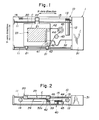
- a first embodiment of the present invention as illustrated in Figs.1 and 2 comprises a carriage which carries and hold a card thereon and transports the same to a reading/writing position and a feeding mechanism for driving the carriage.
- the reader/writer apparatus for an optical memory card has the feeding mechanism 10 for linearly guiding and moving the carriage 20, which carries an optical memory card C thereon, along a longitudinal direction (X-direction) of a support structure 1 perpendicularly with data tracks on the card.
- a support structure 1 perpendicularly with data tracks on the card.
- an optical waveguide holding assembly 33 for holding an tip end 32a of an optical waveguide 32 so as to oppose the same to the data track of the optical memory card and an optical waveguide moving/guiding mechanism 40 for guiding and moving the optical waveguide holding assembly 33 linearly in a direction of the data track.
- a light emitting and receiving unit 31 constituting a reading/writing head together with the optical waveguide 32 is fixed to an end portion of the support structure 1.
- the light emitting and receiving unit 31 includes a laser light emitting element, a photodetecting element, driving circuits therefor, a data reproducing circuit for reproducing reflection signals detected and a data writing circuit for outputting the data to be written in the form of optical signals.
- the light emitting and receiving unit 31 has a function of data writing by irradiation onto the data tracks of the optical memory card or data reproduction by detection of reflected light.
- the unit 31 may be adapted only for reading or for writing.
- the feeding mechanism 10 comprises guide frames 11 provided along the longitudinal sides of the support structure 1, respectively, an X-axis servo-motor 12 functioning as a drive for moving the carriage 20 in an X-axis direction placed on the guide frames 11 and a wire 15 trained over a pulley 13, which is driven to rotate by the motor 12, and another pulley 14 and fixed, at a portion, to the carriage 20.
- the carriage 20 comprises supports 21 for supporting the carriage 20 while allowing the same to be movable, a connecting portion 22 for connecting and fixing the wire 15 thereto, a card setting portion 23 for accommodating and setting the optical memory card C and a window 24 formed at a bottom of the card setting portion 23.
- the optical waveguide holding assembly 33 is adapted to hold the tip ends 32 of the optical waveguide 32 so that they may be substantially vertical with respect to the window 24 and they may change the height as desired.
- the adjustment or changing of the height may be effected, for example, by loosening a bolt 34 pressing the waveguide 32 through a cushioning material such as felt to fix the same and pulling out or retracting the ends of the waveguide 32.
- the optical waveguide holder 33 has, at opposite sides thereof, flanges 36. Through the flanges 36, the optical fiber holder 33 is movably supported on the guide frame 41 of the optical waveguide moving/guiding mechanism 40. A through-hole 35 is formed centrally in the optical waveguide holder 33 so as to extend in the moving direction of the optical waveguide holder 33. A wire 46 is inserted through the through-hole 35 and fixed by a bolt 37.
- the optical waveguide 32 includes optical fibers for light irradiation and optical fibers for light receiving, which are bundled altogether, and opens at the tip end 32a.
- the optical waveguide moving/guiding mechanism 40 has the guide frame 41 provided centrally in the support structure 1 for guiding the tip end 32a of the optical waveguide 32 in a direction perpendicular to the guide frames 11.
- the guide frame 41 comprises members disposed in parallel with each other.
- the optical waveguide 32 is passed through a space defined between the parallel members.
- the optical waveguide holder 33 is supported in such a way that the flanges 36 are placed on the parallel members.
- Pulleys 42, 42 are provided at opposite ends of the guide frame 41.
- the wire 46 is trained over the pulleys 42, 42 so as to be held in parallel with the guide frame 41 and further trained over another pulley 44 through still another pulley 43.
- the pulley 44 is driven to rotate by a Y-axis stepping motor 45 to drive the wire 46.
- the reading or writing of data from or into the optical memory card by the reader/writer apparatus as described above is carried out as follows.
- the reading of the data is exemplarily referred to, but the writing of the data may be effected analogously.
- the optical memory card C is put on the card setting portion 23 of the carriage 20 so that the data storing face may face downwardly.
- the data storing face can be accessible from the lower side through the window 24.
- the carriage 20 is located at an initial position through the wire 15 driven by the X-axis servomotor 12.
- the optical waveguide holder 33 is set to an initial position through the wire 46 driven by the Y-axis stepping motor 45.
- the locations of the carriage 20 and the optical waveguide holder 33 to the respective initial positions are detected, for example, by limit switches (not shown) to automatically stop them at the positions.
- the Y-axis stepping motor 45 is rotated at a constant rate and the rotation is transmitted to the wire 46 through the pulley 44 to convert it to the movement in a longitudinal direction of the wire 46.
- This moves the optical waveguide holder 33, to which a portion of the wire 46 is fixed, along the guide frame 4l.
- laser beam is transmitted from the light emitting and receiving unit 31 through the optical waveguide 32 and emitted from the tip end 32a of the waveguide to irradiate the data track of the optical memory card C through the window 24.
- the irradiated beam is reflected with a reflectivity corresponding to the data storage state on the data track.
- the reflected beam is incident upon the tip end 32a of the optical waveguide and transmitted to the light receiving unit through the waveguide 32.
- the data stored on the data track is read out.
- a stop signal on the track is detected, which actuates a control unit (not shown) to move the carriage 20 to a succeeding track by the X-axis servomotor through the wire 15.
- the number of the tracks may be counted so that the X-axis servomotor 12 can be driven to the track of a desired number.
- the Y-axis stepping motor 45 is rotated reversely by a control unit (not shown) to move the optical waveguide holder 33 to an initial position of the data track to be read out.
- the carriage 20 since the carriage 20 only bears a weight of itself and a weight of the optical memory card, the carriage 20 can be light in weight and it will not apply any substantial load onto the guide frame 11, the wire 15 and the X-axis servomotor 12.
- the optical waveguide moving/guiding mechanism 40 only the weights of the optical waveguide 32 and the optical waveguide holder 33 are applied onto the guide frame 41. Thus, no substantial load is applied to the guide frame 41, the wire 46 and the optical waveguide holder 33.
- the relevant members may be made advantageously of materials light in weight and may be formed smaller.
- the inertia can be reduced, the control for starting and stopping will be easier.
- the optical waveguide is moved in the direction of the data track in the present embodiment, but the moving direction is not limited thereto.
- the holder may be moved in the direction of the data track and the optical waveguide may be moved in a direction perpendicular to the data track.
- the reading and writing of the optical memory card are effected from the lower side of the carriage in the present embodiment, but they may of course be carried out from the upper side of the carriage. In this case, the window 24 may of course be omitted.
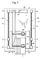
- Figs.6 and 7 illustrate a card holder constituting a second form of a reader/writer apparatus for an optical memory card embodying the present invention.
- the card holder as illustrated in the figures is provided on a base 2, on which a reading/writing position 4 and a card inserting position 6 are provided.
- the card holder comprises a carriage 20, feeding mechanisms 10a, 10b and a regulating member 50.
- the carriage 20 is formed in a concaved shape in section which comprises a horizontal portion 25 and vertical portions 26.
- a groove 27 is formed on the horizontal portion 25 at a position adjacent to one of the vertical portion 26.
- Two guide rollers 29, 29 are provided between the vertical portions 26, 26.
- the feeding mechanisms 10a, 10b are formed identically with each other and supported by the bearings 18, 19.
- Each of the feeding mechanisms 10a, 10b comprises a feed screw 16 to be rotated by a rotation driving means and a moving member 17 meshed with the feed screw 16 and connected and fixed to the vertical portion 26 of the carriage 20.
- the regulating member 50 is fixed, at one end thereof, to a stopper 28 for the carriage so as to be cantilevered over the base 2.
- the free end portion of the regulating member 50 is placed in the groove 27 of the horizontal portion 25 of the carriage 20 along the length thereof, so as to position, in height, around the level of the horizontal portion 25.
- the regulating member 50 is precisely disposed so that the longitudinal side edge thereoof, which is opposite to an inner wall of one of the vertical portions 26 across the guide rollers 29, may extend in parallel with said inner wall, keeping a predetermined space therefrom.
- the regulating member 50 has a tip end 51 formed in curve like a knife to facilitate the insertion of the card.
- a reading/writing head (not shown) is arranged over the reading/writing position 4 on the base 2 of the card holder.
- the head is located above the carriage 20 so as to face the data storing surface of the optical memory card and reads/writes the data from the location.
- the card holder may be reversed to turn upside down for allowing the reading/writing head to be disposed thereunder.
- the card C is moved in an arrow direction to be inserted into the carriage 20.
- the card C follows the curve of the tip end 51 of the regulating member 50 to be guided to the one side of the carriage 20.
- the card is further guided on the horizontal portion 25 in the direction of the arrow, while being pressed by the guide rollers 29.
- Fig.7 explanatorily illustrates the operation.
- a limit switch (not shown) detects the state to actuate the feeding mechanisms 10a, 10b.
- the feed screws 16 are, then, rotated to move the moving members 17, which are meshed with the feed screws 16, respectively, along the feeding mechanisms 10a, 10b.
- the carriage 20 connected thereto is moved on the base 2.
- the two longitudinal edges of the card C placed on the carriage 20 are held by the regulating member 50 and the vertical portion 26 and guided by the regulating member 50 as the carriage 20 is moved.
- the guide roller 29 functions to prevent the card C from being detached or raised.
- the movement of the carriage 20 is stopped.
- the card C is located in a position, while being regulated by the regulating member 50.
- the positioning is effected accurately without play with a simple structure and the reading/writing is carried out soon after the card is put into the reader/writer apparatus.
- practically useful card holder can be provided.
- the reading or writing is carried out by the reading/writing head from the upper side of the carriage in the present embodiment, but the carriage may be provided with a window to effect the reading or writing through the window.
- the base may also have a window.
- Fig.10 is a plan view of a third form of reader/writer apparatus for an optical memory card embodying the present invention.
- a window 24 is formed on the horizontal portion 25 of the carriage 20 of the card holder according to the second embodiment and an optical waveguide moving/guiding mechanism 40 functioning as a reading/writing head is provided on the base 2.
- an optical waveguide moving/guiding mechanism 40 functioning as a reading/writing head
- an optical waveguide holder 33 for holding an optical waveguide 32 so that a tip end 32a of the waveguide 32 may oppose a data track of the optical memory card C and the optical waveguide moving/guiding mechanism, 40 for moving the optical waveguide holder 33 linearly along the direction of the data track while guiding the same.
- a light emitting and receiving unit 31 constituting a reading/writing head together with the optical waveguide 32 is fixed on the base 2.
- the optical memory card C is put onto the horizontal portion 25 of the carriage 20 as in the second embodiment. At this time, the card is used with the data storing surface faced downwardly. Thus, the data storing face can be seen from the lower side through the window 24.
- the optical memory card is transported as in the second embodiment, while the posture of the card is regulated by the regulating member 50.
- the horizontal portion 25 is set to an initial position.
- the optical waveguide holder 33 is set to an initial position by the Y-axis stepping motor 45 through the wire 46.
- the setting to respective initial positions is detected by limit switches (not shown) to automatically stop the carriage and the waveguide holder, respectively.
- the Y-axis stepping motor 45 is rotated at a predetermined rate and the rotation is conveyed to the wire 46 through the pulley 44 to convert the rotation to the movement in the longitudinal direction of the wire 46.
- This moves the optical waveguide holder 33, which is fixed to a portion of the wire 46, along the guide frame 41.
- the number of the tracks may be counted so that the feeding mechanisms 10a, 10b can be driven to the track of a desired number.
- the Y-axis stepping motor 45 is rotated reversely by a control unit (not shown) to move the optical waveguide holder 33 to an initial position of the data track to be read out.
- the present embodiment Since the present embodiment has the advantage of accurate positioning featured in the second embodiment in addition to the feature of the first embodiment, it can have the effect of the second embodiment in addition to the effect of the first embodiment. Thus, the present embodiment can cope with the reading and/or writing of the optical memory card of a high density.
- the optical waveguide moving/guiding mechanism 40 functioning as a reading/writing head is provided on the base 2 in the present embodiment, the base 2 may have a window so that the optical waveguide mechanism 40 may be disposed under the base 2.
- Fig.11 illustrates a dust removing apparatus in a fourth form of a reader/writer apparatus for an optical memory card.
- the dust removing apparatus comprises a carriage 20 encased within an apparatus housing 60, an air blower apparatus 70 and a fan 80.
- a transporting means for transporting the carriage 20 and a reader apparatus (not shown) for reading data from the optical memory card C held by the carriage 20 are provided.
- the housing 60 is closed and substantially sealed except for a card inserting opening 61 and an opening 62 for mounting the fan 80.
- the carriage 20 has a support portion 25a at a lower portion of the horizontal portion 25 for receiving the optical memory card C as an envelope.
- the support portion 25a has, at a central portion thereof, a window 24 so that light beam from the not shown reader may irradiate a data storing face SD of the optical memory card C therethrough.
- the support portion 25a is not always essential and may be omitted or replaced with another means so long as the optical memory card can be held so as not to fall.
- the carriage 20 as used in the first, second or third embodiment may be employed.
- the air blower apparatus 70 comprises an air blowing nozzle 71, an electrically powered air pump 73 with an air tank and an electromagnetic valve 74 which are connected by a piping 72.
- the air blowing nozzle 71 is disposed in the vicinity of one end of the window 24 so as to face the opening of the window 24.
- the electrically powered air pump 73 with the air tank includes a small electrically powered air pump 73b to compress air.
- the compressed air is stored in an air tank 73b.
- the air pump 73a is actuated upon on/off operation of a pressure switch (not shown).
- a valve opening signal is output from a control circuit (not shown) to put the electromagnetic valve 74 into an opened state for several seconds in the embodiment as illustrated.
- the fan 80 is provided at the fan mounting portion 62 formed on the bottom of the housing 60.
- the optical memory card C is inserted between the lower face of the horizontal portion 25 of the carriage and the supporting portion 25a through the card inserting opening 61.
- the optical memory card C is disposed with the data storing face SD thereof positioned at the opening of the window 24 of the supporting portion 25a.
- the insertion of the card is detected by the limit switch 75 and the detection signal is sent to a not shown control circuit to generate a valve opening signal.
- the electromagnetic valve 74 is opened.
- the air compressed and stored in the air tank 73b is fed through the piping 72 and jetted from the air blowing nozzle 71 onto the data storing face SD of the optical memory card through the window 24.
- the jetted air flows along the data storing face SD to blow away dusts adhering on the face.
- the dusts blown off are conveyed by the air flow and sucked in by the fan 80 and discharged out of the housing 60.
- the blown away dusts are conveyed by the air flow so that the dusts are prevented from being re-deposited on the surface of the card. Moreover, the air in the housing 60 is forced to be discharged by the fan 80 so that the inside of the housing 60 is kept as clean as a clean room.
- the electromagnetic valve 74 is opened for several seconds, but it is normally closed. If the pressure of the air tank 73b is lowered during the opening of the valve, the air pump 73a is actuated to feed compressed air to the tank 73b.
- air blowing is carried out when the card is inserted in the embodiment as illustrated, air may be blown when the carriage 20 is being moved in the direction of an arrow as shown in Fig.1.
- a high-speed air stream jetted from the nozzle 71 meets all over the data storing face sequentially, the dust blowing off effect is ensured.
- the card holder carriage as used in the second embodiment is employed in the present embodiment, but the present embodiment may be combined with any other embodiment as described above.
- the present embodiment has an effect of removing dusts adhering to the data storing surface of the optical memory card in the reading or writing of the data to prevent any possible fatal error caused by the dusts adhering to the surface.
- the regulating member 50 used in the second embodiment may also be employed in another embodiment.
- it may be employed in the first embodiment as illustrated in Fig.12.
- a not shown groove is formed under the carriage 20 along the periphery of the card held by the carriage and the regulating member is placed in the groove.
- the operation of the regulating member is substantially the same as in the second embodiment.
- the regulating member may be formed of a plurality of pins instead of using a member formed like a knife configuration as illustrated in Fig.13.
- a pinned regulating member 53 is employed in the reader/writer apparatus of the first embodiment.
- This pinned regulating member has a basic function substantially the same as those of the second and the third embodiment.
- the pinned regulating member has an advantage over them in that the pinning conditions may be adjusted to effect fine adjustment for the card regulation.
Landscapes
- Physics & Mathematics (AREA)
- Engineering & Computer Science (AREA)
- General Physics & Mathematics (AREA)
- Theoretical Computer Science (AREA)
- Electromagnetism (AREA)
- Health & Medical Sciences (AREA)
- General Health & Medical Sciences (AREA)
- Toxicology (AREA)
- Artificial Intelligence (AREA)
- Computer Vision & Pattern Recognition (AREA)
- Optical Recording Or Reproduction (AREA)
- Conveying Record Carriers (AREA)
Applications Claiming Priority (6)
| Application Number | Priority Date | Filing Date | Title |
|---|---|---|---|
| JP61006827A JPS62165733A (ja) | 1986-01-16 | 1986-01-16 | 情報再生装置 |
| JP6827/86 | 1986-01-16 | ||
| JP21996286A JPS6374159A (ja) | 1986-09-18 | 1986-09-18 | カ−ドホルダ |
| JP219962/86 | 1986-09-18 | ||
| JP22272686A JPS6378390A (ja) | 1986-09-20 | 1986-09-20 | カ−ド書込/読取装置における塵埃除去方式 |
| JP222726/86 | 1986-09-20 |
Publications (2)
| Publication Number | Publication Date |
|---|---|
| EP0230275A2 true EP0230275A2 (fr) | 1987-07-29 |
| EP0230275A3 EP0230275A3 (fr) | 1990-01-10 |
Family
ID=27277362
Family Applications (1)
| Application Number | Title | Priority Date | Filing Date |
|---|---|---|---|
| EP87100462A Withdrawn EP0230275A3 (fr) | 1986-01-16 | 1987-01-15 | Appareil de lecture/écriture pour carte à mémoire optique |
Country Status (3)
| Country | Link |
|---|---|
| US (2) | US4933537A (fr) |
| EP (1) | EP0230275A3 (fr) |
| CA (1) | CA1281815C (fr) |
Cited By (6)
| Publication number | Priority date | Publication date | Assignee | Title |
|---|---|---|---|---|
| US4900908A (en) * | 1986-07-25 | 1990-02-13 | Omron Tateisi Electronics Co., Ltd. | Card accessing apparatus having a head disposed under a card feeding stage |
| EP0361935A3 (fr) * | 1988-09-30 | 1991-07-24 | Canon Kabushiki Kaisha | Appareil de traitement d'information comprenant des moyens de production de signal représentant la position relative entre la tête et le milieu |
| US5350910A (en) * | 1988-09-30 | 1994-09-27 | Canon Kabushiki Kaisha | Optical card processing apparatus with means for determining a relative position between head and card |
| EP0617415A3 (fr) * | 1993-03-25 | 1995-01-11 | Canon Kk | Appareil pour enregistrer/reproduire de l'information dans une carte. |
| EP0663649A1 (fr) * | 1994-01-13 | 1995-07-19 | The Whitaker Corporation | Dispositif de connexion au format PCMCIA |
| EP0702315A3 (fr) * | 1994-09-07 | 1997-02-12 | Hitachi Ltd | Lecteur de cartes à chip portable étanche à la poussière |
Families Citing this family (27)
| Publication number | Priority date | Publication date | Assignee | Title |
|---|---|---|---|---|
| JPS6391866A (ja) * | 1986-10-03 | 1988-04-22 | Sony Corp | 光カ−ド記録再生装置 |
| JPH01222391A (ja) * | 1987-11-27 | 1989-09-05 | Nhk Spring Co Ltd | 情報記憶カードリーダライタ |
| US5146069A (en) * | 1988-09-19 | 1992-09-08 | Fuji Photo Film Co., Ltd. | Device for loading and unloading a memory cartridge using a sliding member |
| JP2753595B2 (ja) * | 1990-09-28 | 1998-05-20 | キヤノン株式会社 | 情報記録媒体搬送装置 |
| JPH04263998A (ja) * | 1991-02-19 | 1992-09-18 | Mitsubishi Electric Corp | メモリカード |
| US5219172A (en) | 1991-03-01 | 1993-06-15 | No Peek 21 | Playing card marks and card mark sensor for blackjack |
| US5110134A (en) | 1991-03-01 | 1992-05-05 | No Peek 21 | Card mark sensor and methods for blackjack |
| US5224712A (en) | 1991-03-01 | 1993-07-06 | No Peek 21 | Card mark sensor and methods for blackjack |
| JP3311362B2 (ja) * | 1991-04-10 | 2002-08-05 | 株式会社日本コンラックス | 情報記録再生装置 |
| CA2073802C (fr) * | 1991-08-16 | 2003-04-01 | John Shimmick | Methode et appareil permettant d'apporter simultanement des corrections cylindriques et spheriques a la cornee |
| JPH09245129A (ja) * | 1996-03-06 | 1997-09-19 | Nippon Conlux Co Ltd | カード搬送制御方法および装置 |
| US5689332A (en) * | 1996-09-13 | 1997-11-18 | The University Of Chicago | Automated real-time detection of defects during machining of ceramics |
| US6101155A (en) * | 1997-08-14 | 2000-08-08 | Seagate Technology, Inc. | Lens for optical data storage system |
| US5917788A (en) * | 1997-03-10 | 1999-06-29 | Seagate Technology, Inc. | Lens for optical data storage system |
| US6327241B1 (en) | 1997-04-08 | 2001-12-04 | Seagate Technology Llc | Optical data storage system with lens mount |
| WO1998052193A1 (fr) * | 1997-05-15 | 1998-11-19 | Seagate Technology, Inc. | Systeme de memorisation de donnees a disque optique utilisant un guide d'ondes optiques |
| US5870362A (en) | 1997-06-20 | 1999-02-09 | Seagate Technology, Inc. | Slider for optical disc data storage system |
| US5831797A (en) * | 1997-07-23 | 1998-11-03 | Seagate Technology, Inc. | Slider with mesa for optical disc data storage system |
| DE19738227A1 (de) * | 1997-09-02 | 1999-03-04 | Philips Patentverwaltung | Lademechanismus zum Be- und/oder Entladen eines elektronischen Gerätes mit wenigstens einer Speicherkarte |
| US6445447B1 (en) | 1997-10-27 | 2002-09-03 | Seagate Technology Llc | Near field optical certifying head for disc asperity mapping |
| US6023378A (en) * | 1998-01-20 | 2000-02-08 | Seagate Technology, Inc. | Optical data storage system with improved head lens assembly |
| US6688743B1 (en) | 1998-02-17 | 2004-02-10 | Seagate Technology | Method and apparatus to determine fly height of a recording head |
| US6084846A (en) * | 1998-06-03 | 2000-07-04 | Seagate Technology, Inc. | Liquid immersion lens for optical data storage |
| US6302328B1 (en) | 1998-07-16 | 2001-10-16 | Canon Kabushiki Kaisha | Information recording-reproducing apparatus |
| US6824062B2 (en) * | 1999-05-17 | 2004-11-30 | Kabushiki Kaisha Sankyo Seisakusho | Card transporting mechanism for card reader |
| DE60127468T2 (de) * | 2000-01-24 | 2008-01-31 | Nidec Sankyo Corp. | Manueller Chipkartenleser |
| US20020125316A1 (en) * | 2001-01-26 | 2002-09-12 | Rogers Robert R. | Multi-track linear card reader apparatus and method |
Family Cites Families (30)
| Publication number | Priority date | Publication date | Assignee | Title |
|---|---|---|---|---|
| US3600557A (en) * | 1969-05-27 | 1971-08-17 | Datatype Corp | Data scanner |
| US3939327A (en) * | 1969-08-05 | 1976-02-17 | Data Source Corporation | Optical reading apparatus and method |
| US3703626A (en) * | 1970-12-14 | 1972-11-21 | Data Recognition Corp | Document transport apparatus and method |
| US4030589A (en) * | 1973-04-25 | 1977-06-21 | Ncr Corporation | Data processing machine |
| US3940796A (en) * | 1974-04-05 | 1976-02-24 | American Magnetics Corporation | Card readout apparatus |
| US3921969A (en) * | 1974-06-24 | 1975-11-25 | Docutel Corp | Lead screw document transport |
| FR2304127A1 (fr) * | 1975-03-10 | 1976-10-08 | Fritz Von Ballmoos | Dispositif de controle de l'acces a un etablissement et carte d'entree adaptee a ce dispositif |
| NL176315C (nl) * | 1976-05-12 | 1985-03-18 | Philips Nv | Optische aftastinrichting. |
| US4145758A (en) * | 1977-10-25 | 1979-03-20 | Drexler Technology Corporation | Error checking method and apparatus for digital data in optical recording systems |
| CH640361A5 (de) * | 1979-02-01 | 1983-12-30 | Landis & Gyr Ag | Einrichtung zum thermischen loeschen maschinenlesbarer optischer markierungen. |
| US4269917A (en) * | 1979-07-06 | 1981-05-26 | Drexler Technology Corporation | Data storage medium having reflective particulate silver layer |
| US4278758A (en) * | 1979-07-06 | 1981-07-14 | Drexler Technology Corporation | Process for making a reflective data storage medium |
| US4278756A (en) * | 1979-07-06 | 1981-07-14 | Drexler Technology Corporation | Reflective data storage medium made by silver diffusion transfer |
| US4245151A (en) * | 1979-12-12 | 1981-01-13 | Key Tronic Corporation | Dust dispersion system for a document reader |
| US4301361A (en) * | 1980-05-30 | 1981-11-17 | Autotote, Ltd. | Document handling device providing channels for documents of two widths |
| US4542288A (en) * | 1981-02-27 | 1985-09-17 | Drexler Technology Corporation | Method for making a laser recordable wallet-size plastic card |
| US4500777A (en) * | 1981-02-27 | 1985-02-19 | Drexler Technology Corporation | High data capacity, scratch and dust resistant, infrared, read-write data card for automatic teller machines |
| US4544835A (en) * | 1983-12-29 | 1985-10-01 | Drexler Technology Corporation | Data system containing a high capacity optical contrast laser recordable wallet-size plastic card |
| US4360728A (en) * | 1981-02-27 | 1982-11-23 | Drexler Technology Corporation | Banking card for automatic teller machines and the like |
| US4434360A (en) * | 1981-07-29 | 1984-02-28 | Texas Instruments Incorporated | Optical sensing device for reading bar code or the like |
| US4441018A (en) * | 1982-01-06 | 1984-04-03 | Sealectro Corporation | Card reader with air passage cleaning structure |
| FR2521386A1 (fr) * | 1982-02-11 | 1983-08-12 | Cii Honeywell Bull | Systeme de ventilation d'une cartouche pour disque(s) magnetique(s) amovible(s) et cartouche ventilee par ce systeme |
| JPS58215771A (ja) * | 1982-06-07 | 1983-12-15 | Fujitsu Ltd | デイスク洗浄乾燥装置 |
| US4492855A (en) * | 1982-07-09 | 1985-01-08 | Peripheral Dynamics, Inc. | Badge reader with improved slide arrangement |
| JPS5840692A (ja) * | 1982-08-26 | 1983-03-09 | Oki Electric Ind Co Ltd | 媒体などの位置決め方法 |
| US4581529A (en) * | 1983-08-15 | 1986-04-08 | At&T Bell Laboratories | Read/write system for optical disc apparatus with fiber optics |
| JPS6055576A (ja) * | 1983-09-05 | 1985-03-30 | Toyota Motor Corp | 車両用dadプレ−ヤのディスククリ−ニング装置 |
| US4598196A (en) * | 1984-07-10 | 1986-07-01 | Drexler Technology Corporation | Debit card |
| JPS61224190A (ja) * | 1985-03-29 | 1986-10-04 | Canon Inc | 情報記録再生装置 |
| JPS61239481A (ja) * | 1985-04-16 | 1986-10-24 | Canon Inc | 光デイスク装置 |
-
1987
- 1987-01-14 CA CA000527325A patent/CA1281815C/fr not_active Expired - Fee Related
- 1987-01-15 EP EP87100462A patent/EP0230275A3/fr not_active Withdrawn
- 1987-01-16 US US07/004,343 patent/US4933537A/en not_active Expired - Fee Related
-
1990
- 1990-02-13 US US07/454,241 patent/US4994658A/en not_active Expired - Fee Related
Cited By (11)
| Publication number | Priority date | Publication date | Assignee | Title |
|---|---|---|---|---|
| US4900908A (en) * | 1986-07-25 | 1990-02-13 | Omron Tateisi Electronics Co., Ltd. | Card accessing apparatus having a head disposed under a card feeding stage |
| EP0361935A3 (fr) * | 1988-09-30 | 1991-07-24 | Canon Kabushiki Kaisha | Appareil de traitement d'information comprenant des moyens de production de signal représentant la position relative entre la tête et le milieu |
| US5350910A (en) * | 1988-09-30 | 1994-09-27 | Canon Kabushiki Kaisha | Optical card processing apparatus with means for determining a relative position between head and card |
| EP0716420A3 (fr) * | 1988-09-30 | 1997-10-15 | Canon Kk | Appareil de traitement d'information comprenant des moyens de production de signal représentant la position relative entre la tête et le milieu |
| EP0617415A3 (fr) * | 1993-03-25 | 1995-01-11 | Canon Kk | Appareil pour enregistrer/reproduire de l'information dans une carte. |
| US5808981A (en) * | 1993-03-25 | 1998-09-15 | Canon Kabushiki Kaisha | Information recording/reproducing apparatus capable of movement in two directions of a card-like information recording medium |
| EP0663649A1 (fr) * | 1994-01-13 | 1995-07-19 | The Whitaker Corporation | Dispositif de connexion au format PCMCIA |
| US5637001A (en) * | 1994-01-13 | 1997-06-10 | The Whitaker Corporation | PCMCIA connection device |
| EP0702315A3 (fr) * | 1994-09-07 | 1997-02-12 | Hitachi Ltd | Lecteur de cartes à chip portable étanche à la poussière |
| US5686714A (en) * | 1994-09-07 | 1997-11-11 | Hitachi, Ltd. | Dust-proof portable IC card reader |
| CN1102782C (zh) * | 1994-09-07 | 2003-03-05 | 株式会社日立制作所 | 防灰尘便携式ic卡阅读器 |
Also Published As
| Publication number | Publication date |
|---|---|
| CA1281815C (fr) | 1991-03-19 |
| US4933537A (en) | 1990-06-12 |
| EP0230275A3 (fr) | 1990-01-10 |
| US4994658A (en) | 1991-02-19 |
Similar Documents
| Publication | Publication Date | Title |
|---|---|---|
| US4933537A (en) | Apparatus for controlling movement of an optical memory card for data transfer therewith | |
| EP0386705B1 (fr) | Procédé de traitement de carte optique | |
| JPS60243865A (ja) | デイスク自動交換装置 | |
| JPH0636266B2 (ja) | 情報記録再生装置 | |
| US4149669A (en) | Reading and recording equipment for cards with a magnetic data carrier | |
| US4309601A (en) | Moving head reader mechanism | |
| US5017764A (en) | Apparatus for driving card-like record medium | |
| US5426285A (en) | Modular card read/write apparatus | |
| EP0254328A2 (fr) | Appareil d'accès à une carte | |
| EP0376688B1 (fr) | Porteur de carte | |
| JPH0950492A (ja) | 情報処理装置 | |
| KR100218053B1 (ko) | 카트리지용 필름정보를 판독하기 위한 장치 및 방법 | |
| US4536648A (en) | Optical card read/write scanning system | |
| EP0692783A2 (fr) | Appareil de duplication de bande optique | |
| JPH0567250A (ja) | 複合型カードの記録再生装置 | |
| US20010012183A1 (en) | Disk drive apparatus with a high positional precision magnetic head | |
| JP2001331991A (ja) | 媒体操作装置およびその方法 | |
| US4493540A (en) | Transport apparatus for microfiche cards | |
| JPS62165733A (ja) | 情報再生装置 | |
| JP2025001444A (ja) | カード発行装置 | |
| JPS6280862A (ja) | 記録媒体読取装置 | |
| JPH07287930A (ja) | 情報記録再生装置 | |
| US4483600A (en) | Microfiche card transport apparatus | |
| CA1328692C (fr) | Carte optique et appareil d'enregistrement et de lecture connexe | |
| JPH0531704Y2 (fr) |
Legal Events
| Date | Code | Title | Description |
|---|---|---|---|
| PUAI | Public reference made under article 153(3) epc to a published international application that has entered the european phase |
Free format text: ORIGINAL CODE: 0009012 |
|
| AK | Designated contracting states |
Kind code of ref document: A2 Designated state(s): DE FR GB |
|
| PUAL | Search report despatched |
Free format text: ORIGINAL CODE: 0009013 |
|
| AK | Designated contracting states |
Kind code of ref document: A3 Designated state(s): DE FR GB |
|
| 17P | Request for examination filed |
Effective date: 19900702 |
|
| 17Q | First examination report despatched |
Effective date: 19910730 |
|
| STAA | Information on the status of an ep patent application or granted ep patent |
Free format text: STATUS: THE APPLICATION IS DEEMED TO BE WITHDRAWN |
|
| 18D | Application deemed to be withdrawn |
Effective date: 19930127 |
|
| RIN1 | Information on inventor provided before grant (corrected) |
Inventor name: SUZUKI, HIDEFUMIC/O CSK CORPORATION Inventor name: TAKAHASHI, SHUNZOC/O CSK CORPORATION Inventor name: HASHIMOTO, AKIYOSHIC/O CSK CORPORATION Inventor name: HAMASAKI, YUKIOC/O CSK CORPORATION |