EP0230591A2 - Poutre - Google Patents
Poutre Download PDFInfo
- Publication number
- EP0230591A2 EP0230591A2 EP86117285A EP86117285A EP0230591A2 EP 0230591 A2 EP0230591 A2 EP 0230591A2 EP 86117285 A EP86117285 A EP 86117285A EP 86117285 A EP86117285 A EP 86117285A EP 0230591 A2 EP0230591 A2 EP 0230591A2
- Authority
- EP
- European Patent Office
- Prior art keywords
- longitudinal
- webs
- profile bar
- profile
- carrier
- Prior art date
- Legal status (The legal status is an assumption and is not a legal conclusion. Google has not performed a legal analysis and makes no representation as to the accuracy of the status listed.)
- Granted
Links
- 230000007704 transition Effects 0.000 claims abstract description 5
- 239000006260 foam Substances 0.000 claims description 3
- 239000011324 bead Substances 0.000 claims description 2
- 239000000969 carrier Substances 0.000 description 5
- 238000005452 bending Methods 0.000 description 3
- 238000010276 construction Methods 0.000 description 3
- 230000001133 acceleration Effects 0.000 description 2
- 101100390736 Danio rerio fign gene Proteins 0.000 description 1
- 101100390738 Mus musculus Fign gene Proteins 0.000 description 1
- 230000001154 acute effect Effects 0.000 description 1
- 230000005540 biological transmission Effects 0.000 description 1
- 238000004519 manufacturing process Methods 0.000 description 1
Images
Classifications
-
- E—FIXED CONSTRUCTIONS
- E04—BUILDING
- E04C—STRUCTURAL ELEMENTS; BUILDING MATERIALS
- E04C3/00—Structural elongated elements designed for load-supporting
- E04C3/02—Joists; Girders, trusses, or trusslike structures, e.g. prefabricated; Lintels; Transoms; Braces
- E04C3/04—Joists; Girders, trusses, or trusslike structures, e.g. prefabricated; Lintels; Transoms; Braces of metal
- E04C3/08—Joists; Girders, trusses, or trusslike structures, e.g. prefabricated; Lintels; Transoms; Braces of metal with apertured web, e.g. with a web consisting of bar-like components; Honeycomb girders
-
- B—PERFORMING OPERATIONS; TRANSPORTING
- B25—HAND TOOLS; PORTABLE POWER-DRIVEN TOOLS; MANIPULATORS
- B25J—MANIPULATORS; CHAMBERS PROVIDED WITH MANIPULATION DEVICES
- B25J18/00—Arms
- B25J18/02—Arms extensible
- B25J18/025—Arms extensible telescopic
-
- E—FIXED CONSTRUCTIONS
- E04—BUILDING
- E04C—STRUCTURAL ELEMENTS; BUILDING MATERIALS
- E04C3/00—Structural elongated elements designed for load-supporting
- E04C3/02—Joists; Girders, trusses, or trusslike structures, e.g. prefabricated; Lintels; Transoms; Braces
- E04C3/04—Joists; Girders, trusses, or trusslike structures, e.g. prefabricated; Lintels; Transoms; Braces of metal
- E04C2003/0486—Truss like structures composed of separate truss elements
-
- E—FIXED CONSTRUCTIONS
- E04—BUILDING
- E04C—STRUCTURAL ELEMENTS; BUILDING MATERIALS
- E04C3/00—Structural elongated elements designed for load-supporting
- E04C3/02—Joists; Girders, trusses, or trusslike structures, e.g. prefabricated; Lintels; Transoms; Braces
- E04C3/04—Joists; Girders, trusses, or trusslike structures, e.g. prefabricated; Lintels; Transoms; Braces of metal
- E04C2003/0486—Truss like structures composed of separate truss elements
- E04C2003/0495—Truss like structures composed of separate truss elements the truss elements being located in several non-parallel surfaces
Definitions
- the invention relates to a carrier having at least one profile bar and at least one supporting wall or a supporting body.
- Carriers are required in a wide variety of designs, for example in crane construction or the devices.
- a special area of application for such carriers of the devices is, for example, handling devices such as those used more recently in modern manufacturing processes.
- handling devices with straight basic axes, carriers have to be mounted in a longitudinally displaceable manner on other carriers, which in turn are also moved.
- the slidable storage takes place via rollers, wheels of the like elements. Because the movements are very fast, high axis accelerations occur, which put a heavy load on the beams. As a result, they must be particularly stable. The requirement for high stability is opposed to that for light weight and small acceleration forces.
- the object of the invention is therefore to develop a carrier having at least one profile bar, which enables a lightweight construction due to special profile bar design without impairing rigidity and stability.
- the carrier is designed according to the preamble of claim 1 in accordance with the characterizing part of this claim.
- An essential feature of this carrier is therefore the special design of the profile bar, on the running surface of which the wheel or wheels or the like.
- Another carrier or a carriage or the like are moved along. A force is introduced into the profile bar via the impeller or wheels, which force is derived via the two webs onto the supporting wall or a supporting body.
- the part slidably mounted thereon is only slidably supported on this carrier.
- the total required treads are on at least one profile bar of each carrier.
- the treads are located on two profile bars.
- the carrier can be used particularly universally and one is not subjected to excessive restrictions in this way with regard to the carriages or the like. It is easily possible to provide five or six treads on a single profile bar, which may also be used in pairs or in pairs. In addition, the treads do not have to be particularly pronounced surfaces, but can also be act a flank of a prismatic body or a portion of a wall that does not necessarily have to be flat. In other words, you can move the impeller (s) along an outer surface of the profile bar at the desired location.
- the only decisive factor is that the normal to the touch ellipse runs through the common profile axis, which is defined by the intersection of the center planes through the two webs. It also follows from this that the wheels are, in particular, spherical or spherical wheels. It also follows from this that the "treads" can be relatively narrow if there are any pronounced treads on the outer surface of the profile bar.
- the or each profile bar is thus a load introduction element, via which wheel forces are introduced into the carrier, the latter being a support element or a support body.
- the carrier or the supporting element in turn forwards the forces applied to any supports or a further supporting element.
- a particularly preferred embodiment of the invention is characterized in that the cross section of each profiled bar is symmetrical to an imaginary longitudinal plane through the bisector of the angle enclosed by the two longitudinal webs, the longitudinal webs preferably having a rectangular cross section.
- every profile bar exists from a basic body with one or more treads and two longitudinal bars. The latter are preferably made in one piece with the base body.
- the cross section of the profile bar without longitudinal webs is circular in a further embodiment of the invention.
- an elliptical or possibly also oval cross section can also be expedient.
- the running surfaces do not necessarily have to be present in raised or recessed form, rather they can be formed by partial surfaces of the cylinder jacket. They do not necessarily have to stand out physically, but they may be recognizable by a better surface structure.
- the two webs preferably enclose an angle of approximately 30 ° to 90 °, but in particular of approximately 60 °.
- a further embodiment of the invention is characterized in that the cross section of the profile bar without webs is approximately trapezoidal, the webs being assigned to the short baseline.
- Trapezoid here is not understood to mean the general trapezoidal shape, but the symmetrical trapezoid with inclined surfaces of equal strength, but inclined in opposite directions.
- a further development of the invention is characterized in that the cross-section of the profile bar has approximately the shape of two hexagon faces of different sizes, with their dividing surfaces centered on one another, separated by a corner, a longitudinal web being attached to the two corners of the larger hexagon half and the two longitudinal webs one Include angles of preferably about 60 °.
- This cross-sectional shape is optimal in that it offers the possibility of providing a whole series of running surfaces.
- the overall cross-section is relatively small, which benefits the desired lightweight construction.
- the central hexagonal area of the larger hexagonal half can be slightly grooved according to the drawing of the exemplary embodiment. For the same reason, the removal of the two free corners of the larger hexagon half by the amount also apparent from FIG. 4 is possible and advantageous.
- each outer surface of the smaller half hexagonal prism carries, forms or has one of three running surfaces and one of the two outer surfaces of the larger hexagonal prism each has one of two running surfaces.
- the corner dimensions of the large and the small hexagon preferably behave approximately as 2: 1.
- this cross-sectional shape is not the only possible use of this cross-sectional shape, but only a preferred one.
- each support wall consists of two thin plate-like elements with a honeycomb or rigid foam core connecting them. These connecting walls are characterized on the one hand by their low weight and on the other hand by their good stability and dimensional stability. They are comparable to a sandwich plate.
- the plate-like elements of the supporting wall protrude particularly seen advantageously the core in the transverse direction of the profile bar and the projecting ends are each firmly connected to the two outer surfaces of the associated longitudinal web.
- the plate-like elements are expediently glued, riveted or screwed onto the longitudinal webs. Between the projecting ends of the two free supporting walls, a somewhat more stable end bar is advantageously used, which runs in particular parallel to the respective longitudinal web.
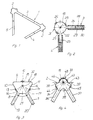
- the carrier 1 shown in Fig. 1 consists of two profile bars 2 of the same cross-sectional shape, which are connected to each other via a support wall 3 and each of which is connected to a further support wall 4 or 5. In this way, a carrier is created sen shape is comparable to that of a triangular tube. For the sake of clarity, the cross sections of the profile bars are exaggerated.
- the profile bars shown in FIG. 1 correspond to the embodiment according to FIG. 4.
- the profile bar shown in Fig. 3 has a base body 6, which can be described as trapezoidal or approximately triangular. With this base body two longitudinal webs 7 and 8 are connected at an angle to each other, in particular manufactured in one piece. They enclose an acute angle 21 of, for example, approximately 60 °.
- tread 12, 13, 14 on at least one, but preferably all three triangular flanks of the triangular base 6.
- These treads are shown as raised treads both in this figure and in FIGS. 2 and 4 for the sake of clarity. However, this is by no means necessary, rather the running surfaces can be partial surfaces of the triangular flanks 9, 10, 11. It is also possible that the treads are formed by groove-like depressions in the triangular flanks. It is only important that the normals to the treads or imaginary perpendicular planes 15, 16, 17, which are perpendicular to the triangular flanks and in particular pass through the center of the tread, intersect in a common longitudinal axis 18 of the profile.
- the base body 22 has a circular cross section, i.e. the basic body has the shape of a circular cylinder.
- the two longitudinal webs 23 and 24 form a right or smaller angle in the exemplary embodiment. Only three treads 25, 26, 27 are shown, for example.
- FIG. 2 The three supporting walls 3, 4, 5, which are only shown schematically in FIG. 1, are drawn in more detail in FIG. 2.
- Each consists of two parallel thin plate-like elements 28 and 29 and a honeycomb or rigid foam core 30 connecting them.
- the plate-like elements preferably protrude beyond the core 30 in the transverse direction of the profile bar 2. This allows them with their projecting edges on the two parallel outer surfaces of the in the Gap between the elements 28 and 29 engaging longitudinal web 23 and 24 are attached. 2 is designated as a whole by 31.
- FIG. 4 shows a third, preferred exemplary embodiment of a profiled rod, which is designated by 2. It has a cross-sectional shape, which can be essentially as follows can write. It consists of two hexagon halves 33 and 34 of different sizes with their separating surfaces placed in the middle, the hexagons being severed at a corner.
- the base body 43 accordingly consists of a larger and a smaller hexagonal prism half.
- the corner dimensions or circumferential diameter of the hexagons of the larger and smaller hexagon behave approximately like 2: 1.
- the central hexagonal surface of the larger hexagonal half according to FIG. 4 can be provided with a groove 35 or the like.
- the two free corners 38, 39 of the larger hexagon half can also be removed somewhat.
- the parts that have been taken away in terms of ideas are drawn partly by dash-dotted lines and partly by the actual contour lines in FIG. 4.
- This profile bar can have, for example and preferably five treads 44 to 48.
- the treads 44 and 47 on the one hand and 45 and 46 on the other hand each form a pair of treads for a corresponding pair of wheels or pairs of wheels.
- two profiled bars of this type on a carrier not all but normally only a part of the treads or pairs of treads are used, in particular the treads 44, 45, 48 on one and 44, 47 or 45, 46 on the other tread bar.
- each web 23, 24 and the adjoining plane support wall 3, 4 lie in a common plane. If the supporting walls are not flat, but are, for example, arched, angular or of a completely different shape, it is in any case true that a common plane must be present in the transition area from the longitudinal web to the subsequent longitudinal supporting wall area. In other words, for example in the case of a flat longitudinal web and a flat supporting wall, the longitudinal center planes of these two elements should not enclose an angle.
- the carrier according to the invention can also consist of only a single profile bar and a single supporting wall, the profile bar also having two longitudinal webs in this case, it is easy to see that each of these two longitudinal webs is or can be assigned a longitudinal edge of the supporting wall.
- the cross-sectional shape of the supporting wall could be approximately C-shaped, for example.
- the supporting wall primarily determines the shear stiffness of the girder, while the profile bars used for load control determine the bending stiffness of the girder.
- the load-bearing capacity of the entire beam is only achieved by combining the two elements.
- the thickness of the thin-walled plate is in particular less than the thickness of the longitudinal webs 7 and 8. It is preferably about 0.3 to 5 mm. At the transition to the associated longitudinal web 7, 8, it may be necessary to adjust the thickness.
- each support wall consists of two thin-walled plates which are connected to one another by webs, the webs in particular running parallel to the longitudinal direction of the carrier.
- the thickness of each of these two plates is preferably on the order of 0.3 to 1.5 mm. This then results in a total thickness of up to approx. 6 or 8 mm.
- This supporting wall can, for example, be connected to the associated longitudinal web in the manner shown in FIG. 2. In the aforementioned case, too, an encirclement of the longitudinal web can be provided, in which case the end region of the thin-walled plate must then be correspondingly adapted in shape.
Landscapes
- Engineering & Computer Science (AREA)
- Architecture (AREA)
- Civil Engineering (AREA)
- Structural Engineering (AREA)
- Robotics (AREA)
- Mechanical Engineering (AREA)
- Rod-Shaped Construction Members (AREA)
- Bridges Or Land Bridges (AREA)
- Handcart (AREA)
- Paper (AREA)
- Surgical Instruments (AREA)
- Glass Compositions (AREA)
- Pallets (AREA)
Priority Applications (1)
| Application Number | Priority Date | Filing Date | Title |
|---|---|---|---|
| AT86117285T ATE52296T1 (de) | 1986-01-29 | 1986-12-11 | Traeger. |
Applications Claiming Priority (2)
| Application Number | Priority Date | Filing Date | Title |
|---|---|---|---|
| DE19863602575 DE3602575A1 (de) | 1986-01-29 | 1986-01-29 | Traeger |
| DE3602575 | 1986-01-29 |
Publications (3)
| Publication Number | Publication Date |
|---|---|
| EP0230591A2 true EP0230591A2 (fr) | 1987-08-05 |
| EP0230591A3 EP0230591A3 (en) | 1988-01-13 |
| EP0230591B1 EP0230591B1 (fr) | 1990-04-25 |
Family
ID=6292836
Family Applications (1)
| Application Number | Title | Priority Date | Filing Date |
|---|---|---|---|
| EP86117285A Expired - Lifetime EP0230591B1 (fr) | 1986-01-29 | 1986-12-11 | Poutre |
Country Status (5)
| Country | Link |
|---|---|
| US (1) | US4829736A (fr) |
| EP (1) | EP0230591B1 (fr) |
| AT (1) | ATE52296T1 (fr) |
| DE (1) | DE3602575A1 (fr) |
| ES (1) | ES2014228B3 (fr) |
Cited By (1)
| Publication number | Priority date | Publication date | Assignee | Title |
|---|---|---|---|---|
| CN103696535A (zh) * | 2013-12-26 | 2014-04-02 | 南京工业大学 | 波纹腹板梁高利用率圆形开洞配件 |
Families Citing this family (1)
| Publication number | Priority date | Publication date | Assignee | Title |
|---|---|---|---|---|
| WO2017066466A1 (fr) * | 2015-10-13 | 2017-04-20 | University Of Notre Dame Du Lac | Modules réglables pour structures à profondeur variable |
Family Cites Families (19)
| Publication number | Priority date | Publication date | Assignee | Title |
|---|---|---|---|---|
| US1527728A (en) * | 1920-06-28 | 1925-02-24 | Firm Luftschiffbau Zeppelin Gm | Hollow bar in two pieces |
| US2003738A (en) * | 1933-09-05 | 1935-06-04 | Cartwright Frank Poole | Fabricated structure and elements thereof |
| US3021014A (en) * | 1959-01-19 | 1962-02-13 | Link Belt Speeder Corp | Crane boom structure |
| CH389204A (de) * | 1961-05-19 | 1965-03-15 | Alusuisse | Laufkranbrücke aus Leichtmetall |
| DE1169095B (de) * | 1961-11-11 | 1964-04-30 | Herbert Kasting | Kastentraeger-Kranbruecke fuer Konsollaufkatze |
| FR1321943A (fr) * | 1962-05-14 | 1963-03-22 | Ind De L Aluminium Sa | Pont roulant en métal léger |
| US3256671A (en) * | 1962-09-13 | 1966-06-21 | Mc Graw Edison Co | Elongated rigid structure |
| US3273299A (en) * | 1963-07-12 | 1966-09-20 | Jr Philip F Hartung | Bipod components and building units containing same |
| DE1559408A1 (de) * | 1965-06-09 | 1969-08-28 | Rensch Eberhard | Rahmenfachwerk |
| DE1608055A1 (de) * | 1967-02-08 | 1970-09-24 | Aisin Seiki | Verfahren zum Herausnehmen von im Gussverfahren hergestellten Gegenstaenden aus der Form |
| SE333050B (fr) * | 1970-05-04 | 1971-03-01 | Linden Alimak Ab | |
| US4416097A (en) * | 1976-02-20 | 1983-11-22 | Weir Richard L | Universal beam construction system |
| GB1555618A (en) * | 1976-05-05 | 1979-11-14 | Dziewolski R | Rigid assembly joint |
| US4171598A (en) * | 1977-10-21 | 1979-10-23 | J. I. Case Company | Hollow boom construction |
| DE8032320U1 (de) * | 1980-12-04 | 1981-04-02 | Liebherr-Werk Ehingen Gmbh, 7930 Ehingen | Metalltraeger |
| FI73401C (fi) * | 1981-08-18 | 1987-10-09 | Coles Cranes Ltd | Bom foer lyftkran eller liknande. |
| FR2530526B1 (fr) * | 1982-07-23 | 1985-11-08 | Ind | Bras de robot |
| DE3313215A1 (de) * | 1983-04-13 | 1984-10-18 | Robert Bosch Gmbh, 7000 Stuttgart | Lineareinheit fuer handhabungsgeraete der industriellen fertigung |
| IT1163808B (it) * | 1983-07-19 | 1987-04-08 | Sadelmi Cogepi Cie Gen Progett | Elemento strutturale per carpenteria metallica e strutture in particolare sostegni per linee aeree di trasmissione di energia elettrica con esso realizzabili |
-
1986
- 1986-01-29 DE DE19863602575 patent/DE3602575A1/de not_active Ceased
- 1986-12-11 AT AT86117285T patent/ATE52296T1/de not_active IP Right Cessation
- 1986-12-11 EP EP86117285A patent/EP0230591B1/fr not_active Expired - Lifetime
- 1986-12-11 ES ES86117285T patent/ES2014228B3/es not_active Expired - Lifetime
-
1987
- 1987-01-20 US US07/005,237 patent/US4829736A/en not_active Expired - Fee Related
Cited By (1)
| Publication number | Priority date | Publication date | Assignee | Title |
|---|---|---|---|---|
| CN103696535A (zh) * | 2013-12-26 | 2014-04-02 | 南京工业大学 | 波纹腹板梁高利用率圆形开洞配件 |
Also Published As
| Publication number | Publication date |
|---|---|
| US4829736A (en) | 1989-05-16 |
| EP0230591B1 (fr) | 1990-04-25 |
| ATE52296T1 (de) | 1990-05-15 |
| ES2014228B3 (es) | 1990-07-01 |
| EP0230591A3 (en) | 1988-01-13 |
| DE3602575A1 (de) | 1987-07-30 |
Similar Documents
| Publication | Publication Date | Title |
|---|---|---|
| DE69103257T2 (de) | Strukturträger. | |
| DE4428310A1 (de) | Befestigungsvorrichtung für ein Werkzeug oder Werkstück | |
| DE2743835A1 (de) | Kugelfuehrung | |
| DE69422292T2 (de) | Universalträger für eine bewegliche last | |
| DE3304783C2 (fr) | ||
| EP4251494B1 (fr) | Bloc modulaire et kit modulaire pour fournir un véhicule robot ou un véhicule logistique | |
| DE102012109586A1 (de) | Kran, insbesondere Brückenkran oder Portalkran, mit mindestens zwei Kranträgern | |
| CH643907A5 (de) | I-foermiges traegerprofil aus leichtmetall. | |
| DE2547897A1 (de) | Profiltraeger | |
| DE4100842C1 (en) | Coil spring with several concentric spring element turns - has symmetrical spring elements to attain coincidence of load and geometrical axes | |
| DE3644743A1 (de) | Waelzlager-geradefuehrung | |
| WO1994022621A1 (fr) | Plaquette de coupe | |
| EP0230591A2 (fr) | Poutre | |
| DE2225707A1 (de) | Zweischienen-foerdersystem | |
| EP0418640B1 (fr) | Cage pour palier à roulement pour mouvements longitudinaux | |
| DE102018133164A1 (de) | Schneidwerkzeug | |
| DE3535524C2 (de) | Abdeckung für Straßenschächte oder -einläufe | |
| DE4143352C2 (de) | Profilstab | |
| EP0997220A2 (fr) | Porte-outil pour machine-outil | |
| DE4106620A1 (de) | Traegerprofil fuer einen verfahrbaren schlitten o. ae. | |
| DE3340355A1 (de) | Radlastwaage | |
| DE2804378C3 (de) | Flanschverbindung zwischen einer Fahrzeugachse und den Längsholmen eines Fahrgestelles | |
| DE4227599A1 (de) | Lineargleitlager | |
| EP3095736A2 (fr) | Ligne de convoyage avec des modules de support de bande de convoyage couplés à des supports transversaux | |
| DE1434504C (de) | Teleskopartig ausziehbarer Schalungs träger |
Legal Events
| Date | Code | Title | Description |
|---|---|---|---|
| PUAI | Public reference made under article 153(3) epc to a published international application that has entered the european phase |
Free format text: ORIGINAL CODE: 0009012 |
|
| AK | Designated contracting states |
Kind code of ref document: A2 Designated state(s): AT CH ES FR GB IT LI |
|
| PUAL | Search report despatched |
Free format text: ORIGINAL CODE: 0009013 |
|
| RHK1 | Main classification (correction) |
Ipc: E04C 3/00 |
|
| AK | Designated contracting states |
Kind code of ref document: A3 Designated state(s): AT CH ES FR GB IT LI |
|
| 17P | Request for examination filed |
Effective date: 19880229 |
|
| 17Q | First examination report despatched |
Effective date: 19890224 |
|
| ITF | It: translation for a ep patent filed | ||
| GRAA | (expected) grant |
Free format text: ORIGINAL CODE: 0009210 |
|
| AK | Designated contracting states |
Kind code of ref document: B1 Designated state(s): AT CH ES FR GB IT LI |
|
| REF | Corresponds to: |
Ref document number: 52296 Country of ref document: AT Date of ref document: 19900515 Kind code of ref document: T |
|
| GBT | Gb: translation of ep patent filed (gb section 77(6)(a)/1977) | ||
| ET | Fr: translation filed | ||
| ITTA | It: last paid annual fee | ||
| PLBE | No opposition filed within time limit |
Free format text: ORIGINAL CODE: 0009261 |
|
| STAA | Information on the status of an ep patent application or granted ep patent |
Free format text: STATUS: NO OPPOSITION FILED WITHIN TIME LIMIT |
|
| 26N | No opposition filed | ||
| REG | Reference to a national code |
Ref country code: CH Ref legal event code: PUE Owner name: VI WATERJET GMBH ROBOTERSYSTEME |
|
| REG | Reference to a national code |
Ref country code: GB Ref legal event code: 732E |
|
| REG | Reference to a national code |
Ref country code: FR Ref legal event code: TP |
|
| REG | Reference to a national code |
Ref country code: ES Ref legal event code: PC2A Owner name: VI WATERJET GMBH ROBOTERSYSTEME |
|
| PGFP | Annual fee paid to national office [announced via postgrant information from national office to epo] |
Ref country code: FR Payment date: 19941123 Year of fee payment: 9 |
|
| PGFP | Annual fee paid to national office [announced via postgrant information from national office to epo] |
Ref country code: CH Payment date: 19941125 Year of fee payment: 9 |
|
| PGFP | Annual fee paid to national office [announced via postgrant information from national office to epo] |
Ref country code: GB Payment date: 19941128 Year of fee payment: 9 |
|
| PGFP | Annual fee paid to national office [announced via postgrant information from national office to epo] |
Ref country code: AT Payment date: 19941129 Year of fee payment: 9 |
|
| PGFP | Annual fee paid to national office [announced via postgrant information from national office to epo] |
Ref country code: ES Payment date: 19941216 Year of fee payment: 9 |
|
| ITPR | It: changes in ownership of a european patent |
Owner name: CESSIONE;VI WATERJET GMBH ROBOTERSYSTEME |
|
| PG25 | Lapsed in a contracting state [announced via postgrant information from national office to epo] |
Ref country code: GB Effective date: 19951211 Ref country code: AT Effective date: 19951211 |
|
| PG25 | Lapsed in a contracting state [announced via postgrant information from national office to epo] |
Ref country code: ES Free format text: LAPSE BECAUSE OF EXPIRATION OF PROTECTION Effective date: 19951212 |
|
| PG25 | Lapsed in a contracting state [announced via postgrant information from national office to epo] |
Ref country code: LI Effective date: 19951231 Ref country code: CH Effective date: 19951231 |
|
| GBPC | Gb: european patent ceased through non-payment of renewal fee |
Effective date: 19951211 |
|
| REG | Reference to a national code |
Ref country code: CH Ref legal event code: PL |
|
| PG25 | Lapsed in a contracting state [announced via postgrant information from national office to epo] |
Ref country code: FR Effective date: 19960830 |
|
| REG | Reference to a national code |
Ref country code: FR Ref legal event code: ST |
|
| REG | Reference to a national code |
Ref country code: ES Ref legal event code: FD2A Effective date: 20010301 |
|
| PG25 | Lapsed in a contracting state [announced via postgrant information from national office to epo] |
Ref country code: IT Free format text: LAPSE BECAUSE OF NON-PAYMENT OF DUE FEES;WARNING: LAPSES OF ITALIAN PATENTS WITH EFFECTIVE DATE BEFORE 2007 MAY HAVE OCCURRED AT ANY TIME BEFORE 2007. THE CORRECT EFFECTIVE DATE MAY BE DIFFERENT FROM THE ONE RECORDED. Effective date: 20051211 |