EP0230701A1 - Einrichtung zum Hinüberbringen von Teilchen aus einer Zone in eine andere - Google Patents
Einrichtung zum Hinüberbringen von Teilchen aus einer Zone in eine andere Download PDFInfo
- Publication number
- EP0230701A1 EP0230701A1 EP86300393A EP86300393A EP0230701A1 EP 0230701 A1 EP0230701 A1 EP 0230701A1 EP 86300393 A EP86300393 A EP 86300393A EP 86300393 A EP86300393 A EP 86300393A EP 0230701 A1 EP0230701 A1 EP 0230701A1
- Authority
- EP
- European Patent Office
- Prior art keywords
- zone
- particles
- gas stream
- gas
- transition
- Prior art date
- Legal status (The legal status is an assumption and is not a legal conclusion. Google has not performed a legal analysis and makes no representation as to the accuracy of the status listed.)
- Granted
Links
Images
Classifications
-
- C—CHEMISTRY; METALLURGY
- C10—PETROLEUM, GAS OR COKE INDUSTRIES; TECHNICAL GASES CONTAINING CARBON MONOXIDE; FUELS; LUBRICANTS; PEAT
- C10G—CRACKING HYDROCARBON OILS; PRODUCTION OF LIQUID HYDROCARBON MIXTURES, e.g. BY DESTRUCTIVE HYDROGENATION, OLIGOMERISATION, POLYMERISATION; RECOVERY OF HYDROCARBON OILS FROM OIL-SHALE, OIL-SAND, OR GASES; REFINING MIXTURES MAINLY CONSISTING OF HYDROCARBONS; REFORMING OF NAPHTHA; MINERAL WAXES
- C10G35/00—Reforming naphtha
- C10G35/04—Catalytic reforming
- C10G35/10—Catalytic reforming with moving catalysts
- C10G35/12—Catalytic reforming with moving catalysts according to the "moving-bed" method
-
- B—PERFORMING OPERATIONS; TRANSPORTING
- B01—PHYSICAL OR CHEMICAL PROCESSES OR APPARATUS IN GENERAL
- B01J—CHEMICAL OR PHYSICAL PROCESSES, e.g. CATALYSIS OR COLLOID CHEMISTRY; THEIR RELEVANT APPARATUS
- B01J8/00—Chemical or physical processes in general, conducted in the presence of fluids and solid particles; Apparatus for such processes
- B01J8/02—Chemical or physical processes in general, conducted in the presence of fluids and solid particles; Apparatus for such processes with stationary particles, e.g. in fixed beds
- B01J8/0207—Chemical or physical processes in general, conducted in the presence of fluids and solid particles; Apparatus for such processes with stationary particles, e.g. in fixed beds the fluid flow within the bed being predominantly horizontal
- B01J8/0214—Chemical or physical processes in general, conducted in the presence of fluids and solid particles; Apparatus for such processes with stationary particles, e.g. in fixed beds the fluid flow within the bed being predominantly horizontal in a cylindrical annular shaped bed
-
- B—PERFORMING OPERATIONS; TRANSPORTING
- B01—PHYSICAL OR CHEMICAL PROCESSES OR APPARATUS IN GENERAL
- B01J—CHEMICAL OR PHYSICAL PROCESSES, e.g. CATALYSIS OR COLLOID CHEMISTRY; THEIR RELEVANT APPARATUS
- B01J8/00—Chemical or physical processes in general, conducted in the presence of fluids and solid particles; Apparatus for such processes
- B01J8/08—Chemical or physical processes in general, conducted in the presence of fluids and solid particles; Apparatus for such processes with moving particles
- B01J8/12—Chemical or physical processes in general, conducted in the presence of fluids and solid particles; Apparatus for such processes with moving particles moved by gravity in a downward flow
- B01J8/125—Chemical or physical processes in general, conducted in the presence of fluids and solid particles; Apparatus for such processes with moving particles moved by gravity in a downward flow with multiple sections one above the other separated by distribution aids, e.g. reaction and regeneration sections
-
- B—PERFORMING OPERATIONS; TRANSPORTING
- B01—PHYSICAL OR CHEMICAL PROCESSES OR APPARATUS IN GENERAL
- B01J—CHEMICAL OR PHYSICAL PROCESSES, e.g. CATALYSIS OR COLLOID CHEMISTRY; THEIR RELEVANT APPARATUS
- B01J2208/00—Processes carried out in the presence of solid particles; Reactors therefor
- B01J2208/00796—Details of the reactor or of the particulate material
- B01J2208/00884—Means for supporting the bed of particles, e.g. grids, bars, perforated plates
Definitions
- the invention relates to apparatus of the type wherein a gas or vapor is used to react with or treat a particulate type of contact material such as a catalyst, which is passing by gravity flow from one reaction or zone to another.
- processes carried out in such an apparatus include various catalytic hydrocarbon conversion techniques such as reforming, hydrotreating, dehydrogenation and dehydrocyclodimerization as well as the associated task of coke-contaminated catalyst regeneration.
- a specific example of a catalyst regeneration apparatus in which a catalyst whose surface has been covered with coke during a catalytic reforming operation, moves downward through a carbon burn-off section, through a halogenation section and into a drying section is shown and described in Greenwood et al., U.S.
- Patent 3,652,231 the subject matter of which is herein incorporated by reference.
- the catalyst moves downwardly in the annular space between a pair of spaced concentric perforated screens and is subjected initially to a first radially flowing recycle flue gas having a relatively low oxygen content and secondly, to a radially flowing second gas containing air, a halogen and steam.
- the first and second gases are each brought into an annular, elongated plenum space surrounding the annular screens and are segregated within the plenum by an annular baffle ring which divides the plenum into two regions.
- this arrangement permits some of the recycle gas to diffuse downwardly into the catalyst region being subjected to the second gas while permitting some of the second gas to diffuse upwardly into the catalyst region being subjected to the first gas. To the extent there is diffusion, it is difficult, if not impossible, to determine if there is any particular location in the annular space in which the catalyst could be sampled so as to provide a sample which could be said to be truly representative of the catalyst after its coked surface had been burned off to a desired extent. In usual practice, although sampling devices such as those shown in U.S.
- Patents 3,786,682 and 3,973,440 do exist, it is common, when attempting to measure the extent to which coke has been burned off, to operate only the burn-off zone of the regenerator without operating lower zones such as halogenation and drying. Then, after the regenerator has been operated for a sufficient number of hours to permit catalyst to pass through the inoperative halogenation and drying zones and to get to the bottom of the vessel, a sample is taken of the catalyst leaving the vessel. Such a method obviously is very time-consuming and is thus sometimes done only upon startup of operation.
- Another object is to provide a transfer apparatus which assists the gravitational movement of particulate contact materials between an upper treatment zone and a lower treatment zone.
- Yet another object is to provide a transfer apparatus which permits the free gravitational movement of particulate contact materials from an upper gas treatment zone to a lower one while preventing upward movement of a gas in the lower zone into the upper zone.
- a particulate contact material such as spherical particles of a catalyst
- the apparatus of the invention comprises the burn-off and chlorination zones of a catalyst re generator
- the catalyst particles are transferred to the apparatus from a reactor where, during the course of reacting with a hydrocarbon stream, they have become at least partially coated with coke.
- the transfer of particles to the upper treatment zone of the instant apparatus may be by means of a lift engager, or other suitable transfer means, which forms no part of the present invention.
- the particular apparatus used to transfer the particles from the lower treatment zone of the instant apparatus to other treatment zones and/or back to the reactor forms no part of the present invention.
- the first or upper treatment zone of the instant apparatus includes a pair of vertically elongated, radially spaced perforated members, such as screens which have been made by helically wrapping and welding wedge-shaped wires around a plurality of support rods.
- a pair of vertically elongated, radially spaced perforated members such as screens which have been made by helically wrapping and welding wedge-shaped wires around a plurality of support rods.
- the screen is cut and rerolled at a 90° angle to its original position to cause the wires to run parallel to the vertical flow path of the catalyst particles.
- the apparatus includes an annular plenum space or region around the aforementioned pair of spaced screens into which a first treatment gas, such as recycle flue gas into which a controlled quantity of air has been added, is introduced.
- the air addition is controlled so that the recycle flue gas will have relatively low oxygen content, such as 0.8%.
- the coke on the particles will be gradually burned off so as to reduce the weight percent of carbon on the particles from about 5% to about 0.2%.
- the treatment gas, together with the products of combustion, will pass into a central vapor collection zone located radially inwardly of the screens.
- the oxygen content be kept quite low in the upper zone since more oxygen would provide a faster carbon burn-off and produce a higher temperature in the catalyst bed. It is well known that elevated temperatures can cause destruction, or at least a reduction in the anticipated life of catalyst particles. However, as hereinafter discussed, it is also essential that enough oxygen be provided that sufficient coke will be burned off in the upper zone that not enough is left on the particles so as to cause them to overheat and be destroyed when they contact the higher oxygen content gas in the lower zone.
- the apparatus further includes a lower cylindrical zone.
- the catalyst particles contained in this zone move downwardly through the zone by gravity as material is withdrawn from the bottom of the zone.
- a transition zone joins the upper and lower zones and uniformly distributes catalyst from the upper zone to the lower zone.
- a recycle flue gas to which a small quantity of oxygen has been added in the form of air, must typically be recycled continuously by a blower to gradually burn off the coked surface on the catalyst.
- no substantial gas flow rates are required since it has been found that the catalyst particles can be reconditioned by merely being soaked in the second gas.
- the second gas is relatively rich in oxygen compared to the first gas and is preferably air to which a chlorination agent such as Cl2, HCl or an organic chloride has been added.
- the second gas is caused to flow slowly upwardly through the lower bed and into the central vapor collection zone.
- the vapor collection zone is defined on its bottom by the upper surface of the catalyst particles in the lower zone and on its sides, at its lower end portion, by the radially inner surface of the inner wall of the transition zone and, at its upper end portion, by the inner perforated wall of the annular upper zone.
- catalyst particles at least in the situation wherein the catalyst contains platinum, are reconditioned by selecting conditions to enable the platinum to be redistributed uniformly over the available surface area of the support. This operation is desirable since the platinum component of the catalyst tends to become unevenly distributed as the coke is burned off the catalyst particles in the upper zone.
- the aforementioned transition zone comprises a pair of inner and outer unperforated wall members which define a vertically elongated, generally annular flow channel through which the catalyst particles leaving the annular upper zone can flow substantially uniformly into the annular outer edge portions of the generally cylindrical lower zone.
- the walls of the transition zone are spaced apart more at the top than the bottom so that they constitute downward extensions of the cylindrical screens which define the upper zone.
- the inner wall of the transition zone is preferably straight for its entire length so as to present a smooth flow surface for the particles.
- the outer wall can also extend straight downwardly so as to provide a transition zone of constant cross-section.
- the outer wall be generally inwardly tapered in an intermediate region between its upper and lower ends.
- the transition zone will have a considerably less area in annular cross-section at its bottom than at its top.
- the volume of catalyst particles which it contains may be considerably reduced as compared to having a zone of the same height and parallel walls which extend down from the screen cylinders. More importantly, the reduction in cross-section will provide a reduction in gas flow as compared to a transition zone of the same height with parallel sides.
- the tapered wall also provides a good mounting location for a sampling structure.
- the vertical dimension of the transition zone should be at least equal to, and preferably greater than, the distance between the screen cylinders. This dimensioning will assure that the pressure drop between the upper and lower zones will not be less than the radial pressure drop across the upper zone.
- the major portion of the first gas will pass radially inwardly through the upper zone screens and into the central collection zone.
- the ascending gas in the lower zone will pass vertically into the central collection zone which is of course at a pressure lower than the pressure of the first and second gases as they enter their associated zones.
- the second gas will not enter the transition zone since it would encounter the considerable back pressure of the catalyst bed therein as well as a small downward flow of the first gas. Rather, it will naturally pass, because of the absence of any back pressure, into the central collection zone. There is an absence of back pressure since the top layer of catalyst particles in the lower zone defines the bottom of the collection zone.
- the height of the transition zone is preferably selected to be of such an extent that a pressure drop will be attained through the catalyst particles in the zone which will be high enough that it will prevent downward flow of the first gas through the zone in an amount which would be sufficient to cause fluidization of the catalyst particles at the juncture of the transition zone and the lower zone. If fluidization could take place, the particles could attrite rapidly.
- the transition zone height should be short enough that at least some relatively small amount of the first gas will continue to flow downwardly. The downward flow of the first gas assists the gravitational flow of catalyst particles through the transition zone.
- a transition height equal to at least the distance between the screens in the first zone is essential with superior results obtained with a transition height equal to at least three times the distance between these screens.
- the catalyst particles in the transition zone are quite uniformly representative of the degree to which coke has been burned off.
- the sampled particles would accurately indicate the treatment level achieved in the burn-off zone. Since the sampling could be done continuously, or at least periodically, it would enable one to better control the regeneration process and minimize possible damage to the catalyst particles by overheating. For example, if sampling determines that not enough coke is being burned off, the oxygen content of the first gas could be increased. Similarly, if the burn-off was found to be sufficiently complete, the oxygen content of the burn-off gas could possibly be reduced.
- the ability to accurately determine the degree of burn-off is of particularly great importance when one considers that catalyst particles which might be allowed to enter the high oxygen content lower zone with a substantial amount of coke still on their surfaces could possibly react so quickly with the oxygen that they would be heated instantly to temperatures upwards of 2000°F. Such high temperatures could fuse the particles together and destroy them while somewhat lower, but still elevated, temperatures could greatly shorten their useful life.
- the oxygen level in the first gas should be just sufficient to cause the catalyst particles leaving the upper burn-off zone to be sufficiently free of coke that they will not experience a damaging increase in temperature when reaching the oxygen-rich lower zone. This minimized oxygen level in the upper zone will also assure that the catalyst particles are subjected to a minimal temperature in the upper zone.
- the useful life of the catalyst particles can be maximized.
- any excess oxygen obviously increases catalyst temperature and thus shortens the catalyst life.
- the ability to achieve even a small decrease in catalyst temperature, especially in the upper zone where the catalyst might reside for an hour or more, is of substantial importance since temperature is so critical to the life of a catalyst.
- the low oxygen content gas in the upper zone cannot burn off all of the coke on the catalyst particles since some will remain at the center of the particle.
- This remainder which might cause the total carbon content to be about 0.2% when leaving the upper zone, will be quickly burned off when the particles first enter the lower zone and are contacted by the high oxygen content gas therein. This burning will naturally cause the particles to be heated but, assuming the particles had their coke reduced to the desired level, will not produce temperatures any higher than those reached at the upper portion of the upper burn-off zone, and the temperature will soon fall to the level of the remainder of the lower zone. Also, since so little coke is present and since it takes a significant amount of time for the oxygen to diffuse into the center of the particles where the remaining coke resides, the slight short term increase in temperature will be of no substantial consequence.
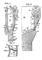
- a preferred embodiment of the apparatus of the present invention comprising a two-stage regenerator section, can be seen to include a vertical pressure vessel indicated generally at 10.
- a removable head section 12 is joined by fastener means, not shown, to the cylindrical outer wall 14 of the vessel.
- An unperforated end ring member 16 is welded at its upper end to the head section 12 and at its lower end to the upper end of a perforated inner screen cylinder 18.
- a plurality of catalyst inlet conduits 20 adapted to receive used catalyst from a reactor or other source, are mounted to, and pass through the head section 12.
- a gas outlet fitting 22 is also mounted to the head section to remove gases from inside the vessel.
- a radially extending screen support flange 24 is mounted between flanges 12 ⁇ , 14 ⁇ on the head section 12 and wall 14 and serves to mount a perforated, outer screen cylinder 26 having an upper end mounting ring portion 27 which depends downwardly.
- the annular space between the inner and outer perforated screen portions 18, 26 defines an upper gas treatment zone 28 which contains a column 30 of used catalyst particles 32 having coke deposits thereon.
- the coke will be of such an extent as to cause carbon to amount to about 5 weight percent of the catalyst particles.
- the zone 28 may also be referred to as a "carbon burn-off" zone since, typically, the coke is substantially removed or burned off as the particles 32 are continually contacted by a stream of a first treatment gas which enters the zone 28 through the gas-vapor inlet means 34 and an annular distribution section 36 between wall 14 and screen 26.
- the first gas is preferably a recycle flue gas such as the gas exiting through outlet 22, to which a sufficient quantity of air has been added to give it a relatively low oxygen content, such as about 0.8%, for example.
- the low oxygen content holds down the rate of carbon burn-off and thus controls the maximum temperature to which the catalyst particles are subjected, thereby protecting them from being overheated.
- the ability of the apparatus to permit accurate sampling can permit adjustments to be made in the oxygen level of the first gas to minimize temperatures and increase catalyst life.
- transition zone 44 defined at its upper end by an inner, unperforated cylindrical end ring member 50 which is welded to the bottom end of the inner perforated screen cylinder 18, and a similar end ring member 52 which is welded to the outer perforated screen cylinder 26.
- the lower end of the transition zone 44 is defined on its inner surface by a cylindrical inner wall portion 54 of a transition element which is welded to the ring member 50.
- the ring 50 could be longer so as to eliminate the need for element 54.
- the transition zone is shown as having a generally downwardly tapered cross-section since its outer wall is defined by an angled cone portion 56 and a vertical portion 58.
- the transition zone has a width equal to the width d of the radial space between the screen 18, 26, while at its bottom, it has a width d ⁇ which is preferably less than 50% of d ⁇ .
- the transition zone 44 could also have parallel side walls, and a constant width annular cross-section, the generally tapered design shown will, for a given height h of the transition zone, cause a decrease in the amount of the first gas which can pass downwardly through the transition zone as compared to a zone of constant width d ⁇ .
- This flow decrease is caused by the increase in back pressure produced by the particles 32 in the catalyst bed when they must pass through a restricted opening.
- the provision of a tapered cross-section for the transition zone 44 also causes an increase in velocity of the particles in the column 30 as they pass downwardly through the transition zone. The downward movement of the particles is assisted by the fact that a small portion of the gas in the upper gas treatment section 36 will flow downwardly, as indicated by the streamlines in Fig. 2.
- the central collection zone 72 will be at a pressure lower than the pressure of the gases entering inlets 34 and 62. Since the top surface 66 ⁇ of the lower treatment zone 66 is defined only by the catalyst particles 32 ⁇ which flow by gravity around the lower edge 54 ⁇ of the inner wall 54 of the transition element, there would be no tendency for the upwardly flowing gas to flow into the transition zone 44. The flow cannot take place since the particles 32 ⁇ in the transition zone would introduce a back pressure on the gas. Also, the small amount of downwardly flowing gas in the transition zone would be at a higher pressure than the pressure in the central collection zone 72.
- the flow rate of the column 30 through the zone 28 and the zone 66 will be determined by the rate at which particles 32 ⁇ leave the zone 66 through outlet 74.
- the particles leaving zone 66 can go on for additional treatment if desired, such as a drying operation, which forms no part of the present invention.
- a sampling apparatus indicated generally at 76 can be utilized.
- the particular type of sampling apparatus used forms no part of the present invention but could comprise a sample bomb 78 having a valve 80 and joined by flange means 82 to an outlet port 84 having a flow control valve 86.
- Fig. 3 is an enlarged sectional view taken on line 3-3 of Fig. 2 and merely illustrates the shape of the annular treatment zone 28, and the fact that the wedge-shaped wires 88, 90 which are welded to rods 92, 94 to form the screens 18, 26, respectively, have slots 96 which are of less dimension that the diameter of the catalyst particles 32 so that gas will flow therethrough but not catalyst particles.
Landscapes
- Chemical & Material Sciences (AREA)
- Organic Chemistry (AREA)
- Chemical Kinetics & Catalysis (AREA)
- Oil, Petroleum & Natural Gas (AREA)
- Physics & Mathematics (AREA)
- Fluid Mechanics (AREA)
- Engineering & Computer Science (AREA)
- General Chemical & Material Sciences (AREA)
- Devices And Processes Conducted In The Presence Of Fluids And Solid Particles (AREA)
- Separation Of Gases By Adsorption (AREA)
- Exhaust Gas Treatment By Means Of Catalyst (AREA)
Priority Applications (4)
| Application Number | Priority Date | Filing Date | Title |
|---|---|---|---|
| AT86300393T ATE51411T1 (de) | 1986-01-21 | 1986-01-21 | Einrichtung zum hinueberbringen von teilchen aus einer zone in eine andere. |
| DE8686300393T DE3669883D1 (de) | 1986-01-21 | 1986-01-21 | Einrichtung zum hinueberbringen von teilchen aus einer zone in eine andere. |
| MYPI87000640A MY100223A (en) | 1986-01-21 | 1987-05-13 | Apparatus for transferring particles from one zone to another. |
| SG77890A SG77890G (en) | 1984-12-24 | 1990-09-25 | Apparatus for transferring particles from one zone to another |
Applications Claiming Priority (1)
| Application Number | Priority Date | Filing Date | Title |
|---|---|---|---|
| US06/686,053 US4567022A (en) | 1984-12-24 | 1984-12-24 | Apparatus for facilitating sampling of particulate matter passing from one treatment zone to another |
Publications (2)
| Publication Number | Publication Date |
|---|---|
| EP0230701A1 true EP0230701A1 (de) | 1987-08-05 |
| EP0230701B1 EP0230701B1 (de) | 1990-03-28 |
Family
ID=24754711
Family Applications (1)
| Application Number | Title | Priority Date | Filing Date |
|---|---|---|---|
| EP86300393A Expired EP0230701B1 (de) | 1984-12-24 | 1986-01-21 | Einrichtung zum Hinüberbringen von Teilchen aus einer Zone in eine andere |
Country Status (5)
| Country | Link |
|---|---|
| US (1) | US4567022A (de) |
| EP (1) | EP0230701B1 (de) |
| JP (1) | JPS62180739A (de) |
| AU (1) | AU573948B2 (de) |
| IN (1) | IN163389B (de) |
Cited By (1)
| Publication number | Priority date | Publication date | Assignee | Title |
|---|---|---|---|---|
| WO2010090800A3 (en) * | 2009-02-06 | 2010-10-28 | Uop Llc | Utilization of baffles in chlorination zone for continuous catalyst regeneration |
Families Citing this family (8)
| Publication number | Priority date | Publication date | Assignee | Title |
|---|---|---|---|---|
| US4567022A (en) * | 1984-12-24 | 1986-01-28 | Uop Inc. | Apparatus for facilitating sampling of particulate matter passing from one treatment zone to another |
| US4665632A (en) * | 1985-09-27 | 1987-05-19 | Uop Inc. | Apparatus for uniformly distributing fluid through a bed of particulate material |
| US5582712A (en) * | 1994-04-29 | 1996-12-10 | Uop | Downflow FCC reaction arrangement with upflow regeneration |
| US7906081B2 (en) * | 2008-05-13 | 2011-03-15 | Uop Llc | Internal grids for adsorbent chambers and reactors |
| US7718146B2 (en) * | 2008-05-13 | 2010-05-18 | Uop Llc | Enhanced bed separation in a styrene monomer reactor using milled plates |
| US7901640B2 (en) | 2008-05-13 | 2011-03-08 | Uop Llc | Optimized counter-current flow baffle |
| US20150224464A1 (en) * | 2014-02-13 | 2015-08-13 | Uop Llc | Radial flow reactor having a side inlet nozzle and methods for reacting hydrocarbons using the same |
| WO2017105786A1 (en) * | 2015-12-16 | 2017-06-22 | Uop Llc | Method and apparatus for catalyst sampling |
Citations (7)
| Publication number | Priority date | Publication date | Assignee | Title |
|---|---|---|---|---|
| US3652231A (en) * | 1969-09-25 | 1972-03-28 | Universal Oil Prod Co | Reconditioning system for moving column of reforming catalyst |
| US3907511A (en) * | 1973-09-20 | 1975-09-23 | Universal Oil Prod Co | Apparatus for countercurrent catalytic contact of a reactant stream in a multiple-stage process |
| US4094817A (en) * | 1977-06-15 | 1978-06-13 | Uop Inc. | Regeneration method for gravity-flowing deactivated catalyst particles |
| US4233268A (en) * | 1971-11-16 | 1980-11-11 | Institut Francais Du Petrole | Apparatus for hydrocarbon conversion |
| EP0154492A2 (de) * | 1984-02-27 | 1985-09-11 | Uop Inc. | Mehrfachstufenreaktorsystem für ein sich bewegendes katalytisches Bett |
| EP0157891A1 (de) * | 1982-09-09 | 1985-10-16 | Uop Inc. | Verfahren zur Behandlung von Gasen in einem bewegten Bett |
| US4567022A (en) * | 1984-12-24 | 1986-01-28 | Uop Inc. | Apparatus for facilitating sampling of particulate matter passing from one treatment zone to another |
Family Cites Families (8)
| Publication number | Priority date | Publication date | Assignee | Title |
|---|---|---|---|---|
| US2440525A (en) * | 1944-06-24 | 1948-04-27 | Standard Oil Dev Co | Dehydrogenation of hydrocarbons |
| US3692496A (en) * | 1971-04-19 | 1972-09-19 | Universal Oil Prod Co | Apparatus for continuous reforming-regeneration process |
| US3706536A (en) * | 1971-05-10 | 1972-12-19 | Universal Oil Prod Co | Multiple-stage stacked reactor system for moving bed catalyst particles |
| US3838039A (en) * | 1971-12-14 | 1974-09-24 | Universal Oil Prod Co | Continuous conversion and regeneration process |
| US3786682A (en) * | 1972-12-22 | 1974-01-22 | Universal Oil Prod Co | Catalyst sampling apparatus |
| US3882015A (en) * | 1973-05-29 | 1975-05-06 | Universal Oil Prod Co | Countercurrent catalytic contact of a reactant stream in a multi-stage process and the apparatus therefor |
| US3973440A (en) * | 1975-04-28 | 1976-08-10 | Universal Oil Products Company | Catalyst sampling method |
| US4167474A (en) * | 1977-06-27 | 1979-09-11 | Uop Inc. | Multiple-stage catalytic reforming with gravity-flowing dissimilar catalyst particles |
-
1984
- 1984-12-24 US US06/686,053 patent/US4567022A/en not_active Expired - Lifetime
-
1986
- 1986-01-21 IN IN57/DEL/86A patent/IN163389B/en unknown
- 1986-01-21 AU AU52546/86A patent/AU573948B2/en not_active Ceased
- 1986-01-21 EP EP86300393A patent/EP0230701B1/de not_active Expired
- 1986-01-27 JP JP61013940A patent/JPS62180739A/ja active Granted
Patent Citations (7)
| Publication number | Priority date | Publication date | Assignee | Title |
|---|---|---|---|---|
| US3652231A (en) * | 1969-09-25 | 1972-03-28 | Universal Oil Prod Co | Reconditioning system for moving column of reforming catalyst |
| US4233268A (en) * | 1971-11-16 | 1980-11-11 | Institut Francais Du Petrole | Apparatus for hydrocarbon conversion |
| US3907511A (en) * | 1973-09-20 | 1975-09-23 | Universal Oil Prod Co | Apparatus for countercurrent catalytic contact of a reactant stream in a multiple-stage process |
| US4094817A (en) * | 1977-06-15 | 1978-06-13 | Uop Inc. | Regeneration method for gravity-flowing deactivated catalyst particles |
| EP0157891A1 (de) * | 1982-09-09 | 1985-10-16 | Uop Inc. | Verfahren zur Behandlung von Gasen in einem bewegten Bett |
| EP0154492A2 (de) * | 1984-02-27 | 1985-09-11 | Uop Inc. | Mehrfachstufenreaktorsystem für ein sich bewegendes katalytisches Bett |
| US4567022A (en) * | 1984-12-24 | 1986-01-28 | Uop Inc. | Apparatus for facilitating sampling of particulate matter passing from one treatment zone to another |
Cited By (1)
| Publication number | Priority date | Publication date | Assignee | Title |
|---|---|---|---|---|
| WO2010090800A3 (en) * | 2009-02-06 | 2010-10-28 | Uop Llc | Utilization of baffles in chlorination zone for continuous catalyst regeneration |
Also Published As
| Publication number | Publication date |
|---|---|
| AU5254686A (en) | 1987-07-23 |
| JPS62180739A (ja) | 1987-08-08 |
| EP0230701B1 (de) | 1990-03-28 |
| US4567022A (en) | 1986-01-28 |
| JPH054131B2 (de) | 1993-01-19 |
| IN163389B (de) | 1988-09-17 |
| AU573948B2 (en) | 1988-06-23 |
Similar Documents
| Publication | Publication Date | Title |
|---|---|---|
| SU1713421A3 (ru) | Аппарат с движущимс слоем катализатора | |
| US5087792A (en) | Process for the dehydrogenation of hydrocarbons | |
| US5130106A (en) | Moving bed radial flow reactor for high gas flow | |
| US3652231A (en) | Reconditioning system for moving column of reforming catalyst | |
| EP0230701A1 (de) | Einrichtung zum Hinüberbringen von Teilchen aus einer Zone in eine andere | |
| KR890002150B1 (ko) | 이동촉매 베드용 다중단 반응기 시스템 | |
| EP0197486A2 (de) | Verfahren und Apparat für Katalysatorregenerierung | |
| EP0200474A1 (de) | Verfahren zum Regenerieren von koksverunreinigtem Katalysator | |
| US4647549A (en) | Regeneration of hydrocarbon conversion catalyst | |
| CN101422716A (zh) | 用于改良径向流动床再生/反应系统效能的方法与装置 | |
| US5151392A (en) | Moving bed regeneration process with separate dispersion and chloriding steps | |
| US4662081A (en) | Process for uniformly distributing fluid through a bed of particulate material | |
| US4637266A (en) | Process for sampling particulate matter passing from one treatment zone to another | |
| JPS59160531A (ja) | 粒体の加熱処理方法およびその装置 | |
| US4687637A (en) | Catalyst regeneration apparatus | |
| US4832921A (en) | Apparatus for regeneration of hydrocarbon conversion catalyst | |
| KR100858772B1 (ko) | 반응 및 재생 시스템 | |
| US4959198A (en) | Downwardly forced particle bed for gas contacting | |
| US5089115A (en) | Downwardly forced particle bed for gas contacting | |
| CA1265658A (en) | Apparatus for transferring particles from one zone to another | |
| IE57244B1 (en) | Apparatus for transferring particles from one zone to another | |
| US5498756A (en) | Moving bed regeneration process with internally mixed chloride gas | |
| US4701429A (en) | Catalyst regeneration with varying air flow to burn-off zone from drying zone through halogenation zone | |
| FI82205B (fi) | Anordning foer oeverfoering av partiklar fraon en zon till en annan. | |
| CN86100750A (zh) | 颗粒区域转移设备 |
Legal Events
| Date | Code | Title | Description |
|---|---|---|---|
| PUAI | Public reference made under article 153(3) epc to a published international application that has entered the european phase |
Free format text: ORIGINAL CODE: 0009012 |
|
| AK | Designated contracting states |
Kind code of ref document: A1 Designated state(s): AT BE CH DE FR GB IT LI NL SE |
|
| 17P | Request for examination filed |
Effective date: 19871022 |
|
| 17Q | First examination report despatched |
Effective date: 19890202 |
|
| RAP1 | Party data changed (applicant data changed or rights of an application transferred) |
Owner name: UOP |
|
| GRAA | (expected) grant |
Free format text: ORIGINAL CODE: 0009210 |
|
| AK | Designated contracting states |
Kind code of ref document: B1 Designated state(s): AT BE CH DE FR GB IT LI NL SE |
|
| REF | Corresponds to: |
Ref document number: 51411 Country of ref document: AT Date of ref document: 19900415 Kind code of ref document: T |
|
| REF | Corresponds to: |
Ref document number: 3669883 Country of ref document: DE Date of ref document: 19900503 |
|
| ITF | It: translation for a ep patent filed | ||
| ET | Fr: translation filed | ||
| PLBE | No opposition filed within time limit |
Free format text: ORIGINAL CODE: 0009261 |
|
| STAA | Information on the status of an ep patent application or granted ep patent |
Free format text: STATUS: NO OPPOSITION FILED WITHIN TIME LIMIT |
|
| ITTA | It: last paid annual fee | ||
| 26N | No opposition filed | ||
| PGFP | Annual fee paid to national office [announced via postgrant information from national office to epo] |
Ref country code: GB Payment date: 19930108 Year of fee payment: 8 |
|
| PGFP | Annual fee paid to national office [announced via postgrant information from national office to epo] |
Ref country code: FR Payment date: 19930111 Year of fee payment: 8 |
|
| PGFP | Annual fee paid to national office [announced via postgrant information from national office to epo] |
Ref country code: AT Payment date: 19930113 Year of fee payment: 8 |
|
| PGFP | Annual fee paid to national office [announced via postgrant information from national office to epo] |
Ref country code: SE Payment date: 19930115 Year of fee payment: 8 |
|
| PGFP | Annual fee paid to national office [announced via postgrant information from national office to epo] |
Ref country code: CH Payment date: 19930125 Year of fee payment: 8 |
|
| PGFP | Annual fee paid to national office [announced via postgrant information from national office to epo] |
Ref country code: NL Payment date: 19930131 Year of fee payment: 8 |
|
| PGFP | Annual fee paid to national office [announced via postgrant information from national office to epo] |
Ref country code: DE Payment date: 19930209 Year of fee payment: 8 |
|
| PGFP | Annual fee paid to national office [announced via postgrant information from national office to epo] |
Ref country code: BE Payment date: 19930226 Year of fee payment: 8 |
|
| PG25 | Lapsed in a contracting state [announced via postgrant information from national office to epo] |
Ref country code: GB Effective date: 19940121 Ref country code: AT Effective date: 19940121 |
|
| PG25 | Lapsed in a contracting state [announced via postgrant information from national office to epo] |
Ref country code: SE Effective date: 19940122 |
|
| PG25 | Lapsed in a contracting state [announced via postgrant information from national office to epo] |
Ref country code: LI Effective date: 19940131 Ref country code: CH Effective date: 19940131 Ref country code: BE Effective date: 19940131 |
|
| BERE | Be: lapsed |
Effective date: 19940131 |
|
| PG25 | Lapsed in a contracting state [announced via postgrant information from national office to epo] |
Ref country code: NL Effective date: 19940801 |
|
| GBPC | Gb: european patent ceased through non-payment of renewal fee |
Effective date: 19940121 |
|
| NLV4 | Nl: lapsed or anulled due to non-payment of the annual fee | ||
| PG25 | Lapsed in a contracting state [announced via postgrant information from national office to epo] |
Ref country code: FR Effective date: 19940930 |
|
| REG | Reference to a national code |
Ref country code: CH Ref legal event code: PL |
|
| PG25 | Lapsed in a contracting state [announced via postgrant information from national office to epo] |
Ref country code: DE Effective date: 19941001 |
|
| REG | Reference to a national code |
Ref country code: FR Ref legal event code: ST |
|
| EUG | Se: european patent has lapsed |
Ref document number: 86300393.5 Effective date: 19940810 |
|
| PG25 | Lapsed in a contracting state [announced via postgrant information from national office to epo] |
Ref country code: IT Free format text: LAPSE BECAUSE OF NON-PAYMENT OF DUE FEES;WARNING: LAPSES OF ITALIAN PATENTS WITH EFFECTIVE DATE BEFORE 2007 MAY HAVE OCCURRED AT ANY TIME BEFORE 2007. THE CORRECT EFFECTIVE DATE MAY BE DIFFERENT FROM THE ONE RECORDED. Effective date: 20050121 |