EP0230754A1 - Séparation de mélanges gazeux - Google Patents
Séparation de mélanges gazeux Download PDFInfo
- Publication number
- EP0230754A1 EP0230754A1 EP86309845A EP86309845A EP0230754A1 EP 0230754 A1 EP0230754 A1 EP 0230754A1 EP 86309845 A EP86309845 A EP 86309845A EP 86309845 A EP86309845 A EP 86309845A EP 0230754 A1 EP0230754 A1 EP 0230754A1
- Authority
- EP
- European Patent Office
- Prior art keywords
- column
- carbon dioxide
- vapour
- fraction
- temperature
- Prior art date
- Legal status (The legal status is an assumption and is not a legal conclusion. Google has not performed a legal analysis and makes no representation as to the accuracy of the status listed.)
- Granted
Links
- 239000008246 gaseous mixture Substances 0.000 title claims description 14
- 238000000926 separation method Methods 0.000 title description 8
- CURLTUGMZLYLDI-UHFFFAOYSA-N Carbon dioxide Chemical compound O=C=O CURLTUGMZLYLDI-UHFFFAOYSA-N 0.000 claims abstract description 261
- 229910002092 carbon dioxide Inorganic materials 0.000 claims abstract description 131
- 239000001569 carbon dioxide Substances 0.000 claims abstract description 130
- VNWKTOKETHGBQD-UHFFFAOYSA-N methane Chemical compound C VNWKTOKETHGBQD-UHFFFAOYSA-N 0.000 claims abstract description 94
- 239000000203 mixture Substances 0.000 claims abstract description 51
- 238000011144 upstream manufacturing Methods 0.000 claims abstract description 6
- 238000000034 method Methods 0.000 claims description 36
- 239000007788 liquid Substances 0.000 claims description 33
- 239000007787 solid Substances 0.000 claims description 14
- 239000012530 fluid Substances 0.000 claims description 13
- 230000008021 deposition Effects 0.000 claims description 8
- 238000001816 cooling Methods 0.000 claims description 3
- OKTJSMMVPCPJKN-UHFFFAOYSA-N Carbon Chemical compound [C] OKTJSMMVPCPJKN-UHFFFAOYSA-N 0.000 claims description 2
- 229910052799 carbon Inorganic materials 0.000 claims description 2
- 238000005086 pumping Methods 0.000 claims description 2
- 238000010438 heat treatment Methods 0.000 claims 1
- 239000007789 gas Substances 0.000 description 19
- IJGRMHOSHXDMSA-UHFFFAOYSA-N Atomic nitrogen Chemical compound N#N IJGRMHOSHXDMSA-UHFFFAOYSA-N 0.000 description 18
- 229910052757 nitrogen Inorganic materials 0.000 description 9
- 238000010586 diagram Methods 0.000 description 7
- 238000004821 distillation Methods 0.000 description 7
- 238000000151 deposition Methods 0.000 description 6
- OWQNOTOYTSUHNE-UHFFFAOYSA-N carbon dioxide methane Chemical compound C.C(=O)=O.C OWQNOTOYTSUHNE-UHFFFAOYSA-N 0.000 description 5
- KDRIEERWEFJUSB-UHFFFAOYSA-N carbon dioxide;methane Chemical compound C.O=C=O KDRIEERWEFJUSB-UHFFFAOYSA-N 0.000 description 5
- 229930195733 hydrocarbon Natural products 0.000 description 5
- 150000002430 hydrocarbons Chemical class 0.000 description 5
- 239000003345 natural gas Substances 0.000 description 5
- 238000004508 fractional distillation Methods 0.000 description 4
- RWSOTUBLDIXVET-UHFFFAOYSA-N Dihydrogen sulfide Chemical compound S RWSOTUBLDIXVET-UHFFFAOYSA-N 0.000 description 3
- 230000001174 ascending effect Effects 0.000 description 2
- 230000000694 effects Effects 0.000 description 2
- 239000012535 impurity Substances 0.000 description 2
- 239000003112 inhibitor Substances 0.000 description 2
- 238000012856 packing Methods 0.000 description 2
- 238000010587 phase diagram Methods 0.000 description 2
- 238000004064 recycling Methods 0.000 description 2
- 238000010992 reflux Methods 0.000 description 2
- 238000001179 sorption measurement Methods 0.000 description 2
- 239000004215 Carbon black (E152) Substances 0.000 description 1
- LSDPWZHWYPCBBB-UHFFFAOYSA-N Methanethiol Chemical compound SC LSDPWZHWYPCBBB-UHFFFAOYSA-N 0.000 description 1
- 239000002250 absorbent Substances 0.000 description 1
- 230000002745 absorbent Effects 0.000 description 1
- 239000000654 additive Substances 0.000 description 1
- 230000000996 additive effect Effects 0.000 description 1
- 230000015572 biosynthetic process Effects 0.000 description 1
- VNWKTOKETHGBQD-YPZZEJLDSA-N carbane Chemical compound [10CH4] VNWKTOKETHGBQD-YPZZEJLDSA-N 0.000 description 1
- 239000000470 constituent Substances 0.000 description 1
- 230000000875 corresponding effect Effects 0.000 description 1
- 238000001704 evaporation Methods 0.000 description 1
- 230000008020 evaporation Effects 0.000 description 1
- 238000012423 maintenance Methods 0.000 description 1
- 238000002156 mixing Methods 0.000 description 1
- 238000012986 modification Methods 0.000 description 1
- 230000004048 modification Effects 0.000 description 1
- 239000002808 molecular sieve Substances 0.000 description 1
- 238000012545 processing Methods 0.000 description 1
- 238000000746 purification Methods 0.000 description 1
- 239000011369 resultant mixture Substances 0.000 description 1
- 229920006395 saturated elastomer Polymers 0.000 description 1
- URGAHOPLAPQHLN-UHFFFAOYSA-N sodium aluminosilicate Chemical compound [Na+].[Al+3].[O-][Si]([O-])=O.[O-][Si]([O-])=O URGAHOPLAPQHLN-UHFFFAOYSA-N 0.000 description 1
- 239000000126 substance Substances 0.000 description 1
- 239000002699 waste material Substances 0.000 description 1
- XLYOFNOQVPJJNP-UHFFFAOYSA-N water Substances O XLYOFNOQVPJJNP-UHFFFAOYSA-N 0.000 description 1
Images


Classifications
-
- F—MECHANICAL ENGINEERING; LIGHTING; HEATING; WEAPONS; BLASTING
- F25—REFRIGERATION OR COOLING; COMBINED HEATING AND REFRIGERATION SYSTEMS; HEAT PUMP SYSTEMS; MANUFACTURE OR STORAGE OF ICE; LIQUEFACTION SOLIDIFICATION OF GASES
- F25J—LIQUEFACTION, SOLIDIFICATION OR SEPARATION OF GASES OR GASEOUS OR LIQUEFIED GASEOUS MIXTURES BY PRESSURE AND COLD TREATMENT OR BY BRINGING THEM INTO THE SUPERCRITICAL STATE
- F25J3/00—Processes or apparatus for separating the constituents of gaseous or liquefied gaseous mixtures involving the use of liquefaction or solidification
- F25J3/02—Processes or apparatus for separating the constituents of gaseous or liquefied gaseous mixtures involving the use of liquefaction or solidification by rectification, i.e. by continuous interchange of heat and material between a vapour stream and a liquid stream
- F25J3/0228—Processes or apparatus for separating the constituents of gaseous or liquefied gaseous mixtures involving the use of liquefaction or solidification by rectification, i.e. by continuous interchange of heat and material between a vapour stream and a liquid stream characterised by the separated product stream
- F25J3/0266—Processes or apparatus for separating the constituents of gaseous or liquefied gaseous mixtures involving the use of liquefaction or solidification by rectification, i.e. by continuous interchange of heat and material between a vapour stream and a liquid stream characterised by the separated product stream separation of carbon dioxide
-
- C—CHEMISTRY; METALLURGY
- C07—ORGANIC CHEMISTRY
- C07C—ACYCLIC OR CARBOCYCLIC COMPOUNDS
- C07C7/00—Purification; Separation; Use of additives
- C07C7/04—Purification; Separation; Use of additives by distillation
-
- F—MECHANICAL ENGINEERING; LIGHTING; HEATING; WEAPONS; BLASTING
- F25—REFRIGERATION OR COOLING; COMBINED HEATING AND REFRIGERATION SYSTEMS; HEAT PUMP SYSTEMS; MANUFACTURE OR STORAGE OF ICE; LIQUEFACTION SOLIDIFICATION OF GASES
- F25J—LIQUEFACTION, SOLIDIFICATION OR SEPARATION OF GASES OR GASEOUS OR LIQUEFIED GASEOUS MIXTURES BY PRESSURE AND COLD TREATMENT OR BY BRINGING THEM INTO THE SUPERCRITICAL STATE
- F25J3/00—Processes or apparatus for separating the constituents of gaseous or liquefied gaseous mixtures involving the use of liquefaction or solidification
- F25J3/02—Processes or apparatus for separating the constituents of gaseous or liquefied gaseous mixtures involving the use of liquefaction or solidification by rectification, i.e. by continuous interchange of heat and material between a vapour stream and a liquid stream
- F25J3/0204—Processes or apparatus for separating the constituents of gaseous or liquefied gaseous mixtures involving the use of liquefaction or solidification by rectification, i.e. by continuous interchange of heat and material between a vapour stream and a liquid stream characterised by the feed stream
- F25J3/0209—Natural gas or substitute natural gas
-
- F—MECHANICAL ENGINEERING; LIGHTING; HEATING; WEAPONS; BLASTING
- F25—REFRIGERATION OR COOLING; COMBINED HEATING AND REFRIGERATION SYSTEMS; HEAT PUMP SYSTEMS; MANUFACTURE OR STORAGE OF ICE; LIQUEFACTION SOLIDIFICATION OF GASES
- F25J—LIQUEFACTION, SOLIDIFICATION OR SEPARATION OF GASES OR GASEOUS OR LIQUEFIED GASEOUS MIXTURES BY PRESSURE AND COLD TREATMENT OR BY BRINGING THEM INTO THE SUPERCRITICAL STATE
- F25J3/00—Processes or apparatus for separating the constituents of gaseous or liquefied gaseous mixtures involving the use of liquefaction or solidification
- F25J3/02—Processes or apparatus for separating the constituents of gaseous or liquefied gaseous mixtures involving the use of liquefaction or solidification by rectification, i.e. by continuous interchange of heat and material between a vapour stream and a liquid stream
- F25J3/0228—Processes or apparatus for separating the constituents of gaseous or liquefied gaseous mixtures involving the use of liquefaction or solidification by rectification, i.e. by continuous interchange of heat and material between a vapour stream and a liquid stream characterised by the separated product stream
- F25J3/0233—Processes or apparatus for separating the constituents of gaseous or liquefied gaseous mixtures involving the use of liquefaction or solidification by rectification, i.e. by continuous interchange of heat and material between a vapour stream and a liquid stream characterised by the separated product stream separation of CnHm with 1 carbon atom or more
-
- F—MECHANICAL ENGINEERING; LIGHTING; HEATING; WEAPONS; BLASTING
- F25—REFRIGERATION OR COOLING; COMBINED HEATING AND REFRIGERATION SYSTEMS; HEAT PUMP SYSTEMS; MANUFACTURE OR STORAGE OF ICE; LIQUEFACTION SOLIDIFICATION OF GASES
- F25J—LIQUEFACTION, SOLIDIFICATION OR SEPARATION OF GASES OR GASEOUS OR LIQUEFIED GASEOUS MIXTURES BY PRESSURE AND COLD TREATMENT OR BY BRINGING THEM INTO THE SUPERCRITICAL STATE
- F25J2200/00—Processes or apparatus using separation by rectification
- F25J2200/04—Processes or apparatus using separation by rectification in a dual pressure main column system
-
- F—MECHANICAL ENGINEERING; LIGHTING; HEATING; WEAPONS; BLASTING
- F25—REFRIGERATION OR COOLING; COMBINED HEATING AND REFRIGERATION SYSTEMS; HEAT PUMP SYSTEMS; MANUFACTURE OR STORAGE OF ICE; LIQUEFACTION SOLIDIFICATION OF GASES
- F25J—LIQUEFACTION, SOLIDIFICATION OR SEPARATION OF GASES OR GASEOUS OR LIQUEFIED GASEOUS MIXTURES BY PRESSURE AND COLD TREATMENT OR BY BRINGING THEM INTO THE SUPERCRITICAL STATE
- F25J2210/00—Processes characterised by the type or other details of the feed stream
- F25J2210/04—Mixing or blending of fluids with the feed stream
-
- F—MECHANICAL ENGINEERING; LIGHTING; HEATING; WEAPONS; BLASTING
- F25—REFRIGERATION OR COOLING; COMBINED HEATING AND REFRIGERATION SYSTEMS; HEAT PUMP SYSTEMS; MANUFACTURE OR STORAGE OF ICE; LIQUEFACTION SOLIDIFICATION OF GASES
- F25J—LIQUEFACTION, SOLIDIFICATION OR SEPARATION OF GASES OR GASEOUS OR LIQUEFIED GASEOUS MIXTURES BY PRESSURE AND COLD TREATMENT OR BY BRINGING THEM INTO THE SUPERCRITICAL STATE
- F25J2220/00—Processes or apparatus involving steps for the removal of impurities
- F25J2220/80—Separating impurities from carbon dioxide, e.g. H2O or water-soluble contaminants
- F25J2220/82—Separating low boiling, i.e. more volatile components, e.g. He, H2, CO, Air gases, CH4
-
- F—MECHANICAL ENGINEERING; LIGHTING; HEATING; WEAPONS; BLASTING
- F25—REFRIGERATION OR COOLING; COMBINED HEATING AND REFRIGERATION SYSTEMS; HEAT PUMP SYSTEMS; MANUFACTURE OR STORAGE OF ICE; LIQUEFACTION SOLIDIFICATION OF GASES
- F25J—LIQUEFACTION, SOLIDIFICATION OR SEPARATION OF GASES OR GASEOUS OR LIQUEFIED GASEOUS MIXTURES BY PRESSURE AND COLD TREATMENT OR BY BRINGING THEM INTO THE SUPERCRITICAL STATE
- F25J2235/00—Processes or apparatus involving steps for increasing the pressure or for conveying of liquid process streams
- F25J2235/80—Processes or apparatus involving steps for increasing the pressure or for conveying of liquid process streams the fluid being carbon dioxide
-
- F—MECHANICAL ENGINEERING; LIGHTING; HEATING; WEAPONS; BLASTING
- F25—REFRIGERATION OR COOLING; COMBINED HEATING AND REFRIGERATION SYSTEMS; HEAT PUMP SYSTEMS; MANUFACTURE OR STORAGE OF ICE; LIQUEFACTION SOLIDIFICATION OF GASES
- F25J—LIQUEFACTION, SOLIDIFICATION OR SEPARATION OF GASES OR GASEOUS OR LIQUEFIED GASEOUS MIXTURES BY PRESSURE AND COLD TREATMENT OR BY BRINGING THEM INTO THE SUPERCRITICAL STATE
- F25J2245/00—Processes or apparatus involving steps for recycling of process streams
- F25J2245/02—Recycle of a stream in general, e.g. a by-pass stream
-
- Y—GENERAL TAGGING OF NEW TECHNOLOGICAL DEVELOPMENTS; GENERAL TAGGING OF CROSS-SECTIONAL TECHNOLOGIES SPANNING OVER SEVERAL SECTIONS OF THE IPC; TECHNICAL SUBJECTS COVERED BY FORMER USPC CROSS-REFERENCE ART COLLECTIONS [XRACs] AND DIGESTS
- Y02—TECHNOLOGIES OR APPLICATIONS FOR MITIGATION OR ADAPTATION AGAINST CLIMATE CHANGE
- Y02C—CAPTURE, STORAGE, SEQUESTRATION OR DISPOSAL OF GREENHOUSE GASES [GHG]
- Y02C20/00—Capture or disposal of greenhouse gases
- Y02C20/40—Capture or disposal of greenhouse gases of CO2
-
- Y—GENERAL TAGGING OF NEW TECHNOLOGICAL DEVELOPMENTS; GENERAL TAGGING OF CROSS-SECTIONAL TECHNOLOGIES SPANNING OVER SEVERAL SECTIONS OF THE IPC; TECHNICAL SUBJECTS COVERED BY FORMER USPC CROSS-REFERENCE ART COLLECTIONS [XRACs] AND DIGESTS
- Y02—TECHNOLOGIES OR APPLICATIONS FOR MITIGATION OR ADAPTATION AGAINST CLIMATE CHANGE
- Y02P—CLIMATE CHANGE MITIGATION TECHNOLOGIES IN THE PRODUCTION OR PROCESSING OF GOODS
- Y02P20/00—Technologies relating to chemical industry
- Y02P20/151—Reduction of greenhouse gas [GHG] emissions, e.g. CO2
-
- Y—GENERAL TAGGING OF NEW TECHNOLOGICAL DEVELOPMENTS; GENERAL TAGGING OF CROSS-SECTIONAL TECHNOLOGIES SPANNING OVER SEVERAL SECTIONS OF THE IPC; TECHNICAL SUBJECTS COVERED BY FORMER USPC CROSS-REFERENCE ART COLLECTIONS [XRACs] AND DIGESTS
- Y10—TECHNICAL SUBJECTS COVERED BY FORMER USPC
- Y10S—TECHNICAL SUBJECTS COVERED BY FORMER USPC CROSS-REFERENCE ART COLLECTIONS [XRACs] AND DIGESTS
- Y10S62/00—Refrigeration
- Y10S62/928—Recovery of carbon dioxide
- Y10S62/929—From natural gas
Definitions
- This invention relates to the separation of gaseous mixtures. It is particularly concerned with the separation of gaseous mixtures comprising carbon dioxide and methane to form a product gas having a reduced concentration of carbon dioxide.
- a mixture of methane and carbon dioxide contains relatively small proportions of carbon dioxide, say, less than 1% by volume the carbon dioxide is typically removed by adsorption, for example using a molecular sieve. It has been alternatively proposed to subject the mixture to distillation at a pressure- of about 650 psia after preliminary treatment to remove any such impurities as hydrogen sulphide and mercaptans that are present in the incoming gas mixture and to reduce the temperature of the mixture to a point at which it is fully saturated or at least partially liquefied. By performing such a distillation the bulk of the gas may be removed from the top of the distillation column free from carbon dioxide while a liquid fraction including 12% by volume of carbon dioxide is removed from the bottom of the column.
- phase diagram of the carbon dioxide - methane system at 650 psia is such that at carbon dioxide concentrations above 12% by volume, solid carbon dioxide will be deposited.
- no more than 12% by volume of carbon dioxide is included in the liquid fraction, and hence if the process is used to treat a mixture containing more than about 1110 by volume of carbon dioxide there will be a substantial loss of product gas which will increase with increasing carbon dioxide concentration in the incoming gas mixture.
- the process therefore, is not suitable for treatment of carbon dioxide - methane mixtures containing more than about 1% by volume of carbon dioxide.
- Fractional distillation has also been employed to separate a carbon dioxide product from natural gas relatively rich in carbon dioxide (e.g. containing more than 20% by volume of carbon dioxide).
- the distillation is performed at a higher pressure, typically 750 psia.
- a higher pressure typically 750 psia.
- the liquid fraction contains substantially pure carbon dioxide and the vapour fraction about 12% carbon dioxide. This process is thus unsuitable if it is desired to obtain a methane product relatively free of carbon dioxide.
- the liquid fraction collecting at the bottom of the low pressure column contains about 12% by volume of carbon dioxide. It is pumped to the high pressure column and thus loss of product methane in this fraction is avoided.
- the vapour fraction collecting at the top of the lower pressure column contains only traces of carbon dioxide and is thus taken as product. It will therefore be appreciated that unlike other fractional distillation processes for separating mixtures of carbon dioxide and methane the process described by Schianni enables a relatively high purity methane product to be produced in high yield. Previous processes had either sacrificed yield for purity or purity for yield.
- the process proposed by Schianni is only suitable for the treatment of mixtures of carbon dioxide and methane having a relatively large carbon dioxide concentration. Schianni states that below about 30 mole per cent of carbon dioxide, the utilitites consumptions of conventional removal systems (of the adsorption kind) are less than that of his distillation process.
- a method for separating a gaseous mixture comprising carbon dioxide and methane including the steps of feeding said mixture into a first liquid-vapour contact column, performing a first rectification of the mixture at a lower pressure in the first liquid-vapour contact column to form a product vapour fraction containing a reduced concentration of carbon dioxide at the top of the column and a fraction enriched in carbon dioxide at the bottom of the column, subjecting the said carbon dioxide-enriched fraction to a second rectification in a second liquid-vapour contact column operating at a higher pressure than said first column and thereby forming at the bottom of the second column a liquid fraction in which carbon dioxide predominates, and at the top of the second column a vapour fraction containing a lower proportion of carbon dioxide than the said carbon dioxide-enriched fraction, and returning fluid from at or near the top of the second column to the first column, the concentrations of the carbon dioxide in the said gaseous mixture and in the said carbon dioxide-enriched fraction and the operating pressures in the columns being selected so as
- the invention also provides apparatus for performing the said method, said apparatus including a first rectification column having an inlet for the feed mixture, a first outlet at or near its top for a product fraction containing a reduced concentration of carbon dioxide, a second outlet at or near its bottom for a fraction enriched in carbon dioxide, pumping means for transferring a stream of said carbon dioxide-enriched fraction to the inlet of a second rectification column adapted to operate at a higher pressure than said first column, said second column having a first outlet at or near its bottom for a fraction in which carbon dioxide predominates, and a second outlet which is at or near its top for a fraction containing less carbon dioxide than the said carbon dioxide-enriched fraction, and which communicates with said first column.
- the concentrations of carbon dioxide that can be tolerated in the gaseous mixture for separation and the carbon dioxide enriched fraction.
- the limits will tend to vary according to whether or not the gaseous mixture contains additional gases such as nitrogen and higher hydrocarbons. Where no such additional gas is present, the carbon dioxide enriched fraction at a typical operating pressure in the lower pressure column of about 41.4. atmospheres absolute may contain up to 12% by volume of carbon dioxide without it depositing solid carbon dioxide in the lower pressure column.
- the gaseous mixture for separation will therefore contain a smaller proportion of carbon dioxide, and typically the method and apparatus according to the invention may be used to separate a gaseous mixture of methane and carbon dioxide containing from 1 to 12% by volume of carbon dioxide and preferably one containing no more than 10% by volume of carbon dioxxde.
- the presence of such constituents as nitrogen and hydrocarbons will tend to have some effect on the maximum amount of carbon dioxide that can be tolerated in the carbon dioxide-enriched fraction and hence will have a corresponding effect on the maximum concentration of carbon dioxide in the feed gas mixture that can be economically catered for.
- Any gaseous impurity such as water hydrogen sulphide or mercaptan may be removed from the gaseous mixture upstream of its introduction into the lower pressure rectification column.
- the method and apparatus according to the invention is particularly suitable for use to treat a natural gas stream that has also to be subjected to a cryogenic or low temperature nitrogen rejection process.
- nitrogen present in the "raw" natural gas is separated from the natural gas in one or more rectification columns.
- the method according to the invention can be economically integrated with such a nitrogen rejection process in a single plant.
- the method and apparatus according to the invention make it possible to reduce substantially the concentration of carbon dioxide in a mixture of methane and carbon dioxide including up to about 12% by volume carbon dioxide without any substantial loss of methane.
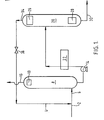
- a feed stream of a mixture of carbon dioxide and methane is cooled from ambient temperature (by means not shown) to a temperature at or near its dew point and is passed to a pipeline 2 communicating with the inlet 6 of a first rectification column 8.
- the stream is uni:ed with a second stream comprising carbon dioxide and methane at the union of the pipeline 2 with a pipeline 4 through which the said second stream flows.
- Both streams are at a pressure of, say, 41.4 atmospheres.
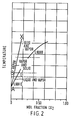
- Their repsective temperatures and compositions are typically such that after mixing the resulting mixture lies on/or just to the left of the line AB in Figure 2 and does not have a temperature above that of the point B.
- the resultant mixture then passes through the inlet 6 into first recification column 8 fitted with a condenser 10.
- the rectification column 8 in this example is operated at an average pressure of 41.4 atmospheres absolute.
- ascending vapour comes into intimate mass exchange relationship with a descending liquid.
- the column 8 may be provided with trays or with a packing (not shown) in order to facilitate this contact between the liquid and the vapour.
- the liquid becomes progressively richer in carbon dioxide as it descends the column 8.
- the vapour becomes progressively richer in methane as it ascends the column 8.
- a liquid fraction comprising 12% by volume of carbon dioxide and 88% by volume of methane collects at the bottom of the column 8 and is withdrawn therefrom by a pump 14.
- a methane-rich vapour collects at the top of the column 8 and some of this vapour is condensed in the condenser 10 and thus flows back down the column as liquid reflux.
- Uncondensed vapour which may, if desired, comprise methane and be substantially free of carbon dioxide, or which may include small amounts of carbon dioxide in addition to methane, is taken from the top of the column 8 through the outlet 16 as a product stream.
- This product stream may be warmed to ambient temperature, thus providing cooling for the incoming stream of methane and carbon dioxide.
- the cold product stream additionally contains nitrogen, it may be further processed to reject the nitrogen prior to being warmed to ambient temperature.
- the liquid taken from the bottom of the column 8 by operation of the pump 14 is then introduced into a second rectification column 20 operating at a higher pressure than the first rectification column 8.
- the rectification column 20 operates at an average pressure of 49.3 atmospheres.
- a heat exchanger 22 is typically employed. Partial or complete evaporation of the liquid may take place in the heat exchanger 22.
- the heat exchanger 22 may be integrated into a nitrogen rejection plant (not shown). Alternatively, or in addition, it can provide cooling for the stream passing through the pipeline 2.
- the rectification column 20 is provided at its top with a condenser 26 so as to provide reflux, and a reboiler 28 at its bottom so as to provide reboil.
- the column 20 is provided with suitable distillation trays or plates (or packing) in order to facilitate intimate contact between a descending liquid and an ascending vapour. There is thus mass exchange between the vapour and the liquid. In consequence, the liquid becomes progressively richer in carbon dioxides as it descends the column, and the vapour becomes progressively richer in methane as it ascends the column.
- a liquid comprising a major proportion of carbon dioxide and a minor proportion of methane collects at the bottom of the second rectification column 20. Some of this liquid is reboiled and the remainder is withdrawn through an outlet 30. If desired, the stream taken from the bottom of the column 20 may be an essentially pure carbon dioxide product. This is not however essential to the invention, and, alternatively, the carbon dioxide stream may be treated as a waste stream and discharged to the environment after it has been warmed to ambient temperature (in this example by heat exchange with the incoming feed stream).
- vapour reaching the top of the column 20 is condensed, and the remainder is withdrawn through an outlet 34 as a stream containing a mahor proportion of methane and a minor proportion of carbon dioxide (though typically, but not necessarily, the proportion of carbon dioxide is greater than that in the feed stream).
- the stream withdrawn through the outlet 34 is then expanded through a throttling valve 36 and the resultant fluid is then passed to the pipeline 4 to be united with the incoming feed stream entering the plant through the pipeline 2. It will be appreciated that such recycling of the vapour from the top of the rectification column 20 increases the concentration of carbon dioxide in the fluid entering the first rectification column 8.
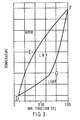
- Figures 2 and 3 both illustrate the constraints that are placed on the selection of the operating pressures for the rectification columns 8 and 20 in Figure 1 and on the temperatures and compositions of the feeds to these columns.
- Figure 2 is a liquid-vapour equilibrium diagram for the carbon dioxide-methane system at the average pressure that obtains in the column 8. It can be seen from Figure 2 that in order to give relatively pure methane product and to avoid the deposition of solid carbon dioxide, the rectification column has to operate within the confines of the generally triangular area ABC of the phase diagram. At point C the mole fraction of carbon dioxide in the mixture is 0.12. Thus the rectification column 8 needs to be operated such that the concentration of carbon dioxide in the liquid that is produced at the bottom of the column does not exceed 12% by volume.
- the temperature of the gaseous mixture introduced into the inlet 6 will need to be not greater than the temperature of the line BC and this places a further limitation on the maximum amount of carbon dioxide that can be tolerated in the feed to the inlet 6, the point B defining the maximum.
- all points within the operating area DEFG are of a higher temperature than any point in the operating area ABC. It is thus preferable when operating the columns 8 and 20 at average pressures of 41.4 and 49.3 atmospheres respectively to raise the temperature of the liquid fraction taken from the bottom of the column 8 to a temperature above that of the point D. This may also involve at least partially vaporising the liquid. It is necessary that the temperature and composition of the vapour leaving the top of the column 20 are such that after passage through the valve 36, which is effective to reduce the pressure of the vapour to that which obtains in the first column 8 the vapour has a temperature and composition that lie on a point to the left of line BX in Figure 2.
- the proportion-of carbon dioxide in the feed gas mixture will determine the optimum average operating pressures for the columns. The higher the percentage carbon dioxide in the feed gas mixture, the lower is the optimum pressure difference between the two columns.
- the plant shown in Figure 4 of the accompanying drawings in comparison to the plant shown in Figure 1, has an additional heat exchanger 38.
- the heat exchanger 38 has means (not shown) for raising the temperature of the vapour leaving the top of the column 20.
- the heat exchanger 38 is thus operated so as to raise the temperature of this vapour to a value such that after throttling in the valve 36 (with its concomitant temperature reduction) the temperature and composition of the vapour are represented by a point lying to the left of the line BX in Figure 2 and thus the vapour remains entirely in the vapour phase.
- this vapour Downstream of the throttling valve 36, this vapour is mixed with the feed stream entering the pipeline 2 to form a mixture whose temperature and composition is such that the mixture lies on or a little to the left of the line AB shown in Figure 2.
- the temperature of the mixture may be admitted by heat exchange in the heat exchanger 41.
- the plant shown in Figure 4 is identical to that shown in Figure 1.
- the plant shown in Figure 5 of the accompanying drawings has an additional heat exchanger 40.
- the heat exchanger 40 has means (not shown) for lowering the temperature of the vapour leaving the top of the column 30 such that it is first condensed and then sub-cooled to a temperature below that of the in Figure 2 and such that allowing the throttling valve 36 the fluid has a temperature below that of point C.
- the carbon dioxide-methane mixture may remain in the liquid state or be at least partially vaporised.
- the expanded fluid Downstream of the valve 36, the expanded fluid is then mixed with the feed stream passing through the pipeline 2.
- the temperature of the mixture may be adjusted by passing it through a heat exchanger 42 upstream of its introduction into the column 8 through the inlet 6.
- the column 8 is provided with a reboiler 44 to provide reboil, and typically there are one or two liquid-vapour contact trays in the section of the column intermediate the feed level and the reboiler.
- the plants shown in Figures 1 and 4 may be provided with similar heat exchangers 42 and reboilers 44.
- the plant shown in Figure 5 is similar to that shown in Figure 1.
- the plant shown in Figure 4 or Figure 5 may be used to separate a mixture comprising 93% by volume of methane and 7% by volume of carbon dioxide.
- the column 8 separates the incoming mixture into a liquid (at the bottom of the column) comprising 12% by volume of carbon dioxide and 88% by volume of methane, and a vapour (at the top of the column) comprising 98.6% by volume of methane and 1.4% by volume of carbon dioxide.
- the column 20 separates the liquid fraction from the column 8 into a liquid (at the bottom of the column) comprising 90% by volume of carbon dioxide and 10% by volume of methane and a vapour (at the top of the column) comprising 91% by volume of methane and 9% by volume of carbon dioxide.
- a liquid at the bottom of the column
- methane-carbon dioxide 7%) mixture entering the pipeline 2 upstream of its union with the pipeline 4 per unit time
- 1681 cubic metres of liquid are withdrawn from the bottom of the column 8 per unit time
- 937.8 cubic metres of vapour are withdrawn from the top of the column 8 per unit time
- 62.2 cubic metres per unit time of liquid are withdrawn from the bottom of column 28 through the outlet 30.
Landscapes
- Engineering & Computer Science (AREA)
- Chemical & Material Sciences (AREA)
- Organic Chemistry (AREA)
- Mechanical Engineering (AREA)
- Thermal Sciences (AREA)
- General Engineering & Computer Science (AREA)
- Physics & Mathematics (AREA)
- Chemical Kinetics & Catalysis (AREA)
- Oil, Petroleum & Natural Gas (AREA)
- Water Supply & Treatment (AREA)
- Analytical Chemistry (AREA)
- General Chemical & Material Sciences (AREA)
- Separation By Low-Temperature Treatments (AREA)
- Organic Low-Molecular-Weight Compounds And Preparation Thereof (AREA)
- Carbon And Carbon Compounds (AREA)
Applications Claiming Priority (2)
| Application Number | Priority Date | Filing Date | Title |
|---|---|---|---|
| GB858531686A GB8531686D0 (en) | 1985-12-23 | 1985-12-23 | Separation of gaseous mixtures |
| GB8531686 | 1985-12-23 |
Publications (2)
| Publication Number | Publication Date |
|---|---|
| EP0230754A1 true EP0230754A1 (fr) | 1987-08-05 |
| EP0230754B1 EP0230754B1 (fr) | 1992-07-15 |
Family
ID=10590220
Family Applications (1)
| Application Number | Title | Priority Date | Filing Date |
|---|---|---|---|
| EP86309845A Expired - Lifetime EP0230754B1 (fr) | 1985-12-23 | 1986-12-17 | Séparation de mélanges gazeux |
Country Status (7)
| Country | Link |
|---|---|
| US (1) | US4759786A (fr) |
| EP (1) | EP0230754B1 (fr) |
| JP (1) | JPS62217090A (fr) |
| AU (1) | AU588069B2 (fr) |
| DE (1) | DE3686039T2 (fr) |
| GB (2) | GB8531686D0 (fr) |
| ZA (1) | ZA869592B (fr) |
Families Citing this family (18)
| Publication number | Priority date | Publication date | Assignee | Title |
|---|---|---|---|---|
| US4952223A (en) * | 1989-08-21 | 1990-08-28 | The Boc Group, Inc. | Method and apparatus of producing carbon dioxide in high yields from low concentration carbon dioxide feeds |
| US5035732A (en) * | 1990-01-04 | 1991-07-30 | Stone & Webster Engineering Corporation | Cryogenic separation of gaseous mixtures |
| US5100635A (en) * | 1990-07-31 | 1992-03-31 | The Boc Group, Inc. | Carbon dioxide production from combustion exhaust gases with nitrogen and argon by-product recovery |
| US5233837A (en) * | 1992-09-03 | 1993-08-10 | Enerfex, Inc. | Process and apparatus for producing liquid carbon dioxide |
| US6098425A (en) * | 1993-10-01 | 2000-08-08 | Stothers; William R. | Thermodynamic separation |
| US5673571A (en) * | 1996-03-06 | 1997-10-07 | Manley; David B. | Deethanizer/depropanizer sequences with thermal and thermo-mechanical coupling and component distribution |
| US5768913A (en) * | 1997-04-16 | 1998-06-23 | Stone & Webster Engineering Corp. | Process based mixed refrigerants for ethylene plants |
| US5953936A (en) * | 1997-10-28 | 1999-09-21 | Air Products And Chemicals, Inc. | Distillation process to separate mixtures containing three or more components |
| US5918481A (en) * | 1997-11-20 | 1999-07-06 | Alliedsignal Inc. | Process for separating hydrogen fluoride from fluorocarbons |
| US6070431A (en) * | 1999-02-02 | 2000-06-06 | Praxair Technology, Inc. | Distillation system for producing carbon dioxide |
| US6276167B1 (en) * | 1999-03-25 | 2001-08-21 | Westlake Technology Corporation | Refrigeration production |
| US6205813B1 (en) * | 1999-07-01 | 2001-03-27 | Praxair Technology, Inc. | Cryogenic rectification system for producing fuel and high purity methane |
| JP4495279B2 (ja) * | 1999-10-12 | 2010-06-30 | 大陽日酸株式会社 | 蒸留装置並びに酸素同位体重成分の濃縮方法および重酸素水の製造方法 |
| US6516631B1 (en) * | 2001-08-10 | 2003-02-11 | Mark A. Trebble | Hydrocarbon gas processing |
| US7152428B2 (en) * | 2004-07-30 | 2006-12-26 | Bp Corporation North America Inc. | Refrigeration system |
| RU2272973C1 (ru) * | 2004-09-24 | 2006-03-27 | Салават Зайнетдинович Имаев | Способ низкотемпературной сепарации газа (варианты) |
| MY157703A (en) * | 2009-06-11 | 2016-07-15 | Ortloff Engineers Ltd | Hydrocarbon gas processing |
| DE102016011356A1 (de) * | 2016-09-20 | 2018-03-22 | Linde Aktiengesellschaft | Verfahren und Anlage zur Herstellung eines Erdgassubstituts und eines Kohlendioxidprodukts |
Citations (2)
| Publication number | Priority date | Publication date | Assignee | Title |
|---|---|---|---|---|
| US2888807A (en) * | 1955-10-06 | 1959-06-02 | Constock Liquid Methane Corp | Process of removing carbon dioxide from natural gas |
| DE3510097A1 (de) * | 1985-03-20 | 1986-09-25 | Linde Ag, 6200 Wiesbaden | Verfahren zum abtrennen von co(pfeil abwaerts)2(pfeil abwaerts) aus einem gasgemisch |
Family Cites Families (14)
| Publication number | Priority date | Publication date | Assignee | Title |
|---|---|---|---|---|
| GB479106A (en) * | 1935-05-28 | 1938-01-31 | Lummus Co | Improvements in or relating to distillation |
| GB523139A (en) * | 1938-06-11 | 1940-07-05 | Rheinmetall Borsig Ag | Improvements in and relating to processes for continuous fractional distillation |
| GB707173A (en) * | 1950-09-28 | 1954-04-14 | Ruetgerswerke Ag | An improved method for the dephenolation of aqueous salt solutions by distillation, in the course of a phenol recovery process |
| US2768118A (en) * | 1951-11-08 | 1956-10-23 | Black Sivalis & Bryson Inc | Method for obtaining condensate from high pressure hydrocarbon fluid in the form of a stabilized product |
| US3230156A (en) * | 1961-09-08 | 1966-01-18 | Chemical Construction Corp | Purification of synthetic methanol by plural stage distillation |
| GB998822A (en) * | 1963-10-28 | 1965-07-21 | Marley Co | A fill assembly for a counterflow water cooling tower |
| US3313724A (en) * | 1965-03-29 | 1967-04-11 | Lummus Co | Process for the separation of normally gaseous hydrocarbon mixtures |
| US3518165A (en) * | 1968-03-29 | 1970-06-30 | Universal Oil Prod Co | Process for separating alkylation effluent by plural stage distillation with benzene recycle |
| GB1478459A (en) * | 1974-08-22 | 1977-06-29 | Cryoplants Ltd | Liquid-vapour contact column |
| US4318723A (en) * | 1979-11-14 | 1982-03-09 | Koch Process Systems, Inc. | Cryogenic distillative separation of acid gases from methane |
| US4315802A (en) * | 1980-05-12 | 1982-02-16 | The Lummus Company | Process and apparatus for fractionating close boiling components of a multi-component system |
| GB2107597B (en) * | 1981-10-01 | 1985-02-27 | Lummus Co | Process and apparatus for fractionating close-boiling components of a multi-component system |
| US4511382A (en) * | 1983-09-15 | 1985-04-16 | Exxon Production Research Co. | Method of separating acid gases, particularly carbon dioxide, from methane by the addition of a light gas such as helium |
| GB8512562D0 (en) * | 1985-05-17 | 1985-06-19 | Boc Group Plc | Liquid-vapour contact method |
-
1985
- 1985-12-23 GB GB858531686A patent/GB8531686D0/en active Pending
-
1986
- 1986-12-16 GB GB8630037A patent/GB2184665B/en not_active Expired - Fee Related
- 1986-12-17 EP EP86309845A patent/EP0230754B1/fr not_active Expired - Lifetime
- 1986-12-17 DE DE8686309845T patent/DE3686039T2/de not_active Expired - Fee Related
- 1986-12-19 ZA ZA869592A patent/ZA869592B/xx unknown
- 1986-12-22 AU AU66835/86A patent/AU588069B2/en not_active Ceased
- 1986-12-22 US US06/945,439 patent/US4759786A/en not_active Expired - Lifetime
- 1986-12-23 JP JP61307597A patent/JPS62217090A/ja active Pending
Patent Citations (2)
| Publication number | Priority date | Publication date | Assignee | Title |
|---|---|---|---|---|
| US2888807A (en) * | 1955-10-06 | 1959-06-02 | Constock Liquid Methane Corp | Process of removing carbon dioxide from natural gas |
| DE3510097A1 (de) * | 1985-03-20 | 1986-09-25 | Linde Ag, 6200 Wiesbaden | Verfahren zum abtrennen von co(pfeil abwaerts)2(pfeil abwaerts) aus einem gasgemisch |
Also Published As
| Publication number | Publication date |
|---|---|
| JPS62217090A (ja) | 1987-09-24 |
| ZA869592B (en) | 1988-08-31 |
| GB8630037D0 (en) | 1987-01-28 |
| AU588069B2 (en) | 1989-09-07 |
| US4759786A (en) | 1988-07-26 |
| DE3686039D1 (de) | 1992-08-20 |
| EP0230754B1 (fr) | 1992-07-15 |
| GB8531686D0 (en) | 1986-02-05 |
| GB2184665A (en) | 1987-07-01 |
| DE3686039T2 (de) | 1993-01-07 |
| GB2184665B (en) | 1990-05-09 |
| AU6683586A (en) | 1987-06-25 |
Similar Documents
| Publication | Publication Date | Title |
|---|---|---|
| US4759786A (en) | Separation of gaseous mixtures | |
| US5992175A (en) | Enhanced NGL recovery processes | |
| EP0029678B1 (fr) | Récupération d'hydrocarbures en C2 à partir d'un courant de tête d'un déméthaniseur | |
| EP0965564B1 (fr) | Système de production de dioxyde de carbone avec un condensateur intégral du gaz d'évent | |
| US5335504A (en) | Carbon dioxide recovery process | |
| EP0095739B1 (fr) | Elimination de l'azote d'un gaz naturel contenant du bioxyde de carbone et de l'azote à taux variable | |
| EP0633438B1 (fr) | Séparation de l'air | |
| US4878932A (en) | Cryogenic rectification process for separating nitrogen and methane | |
| US6308532B1 (en) | System and process for the recovery of propylene and ethylene from refinery offgases | |
| US5551258A (en) | Air separation | |
| US20040200353A1 (en) | Removing natural gas liquids from a gaseous natural gas stream | |
| US4525187A (en) | Dual dephlegmator process to separate and purify syngas mixtures | |
| US4732598A (en) | Dephlegmator process for nitrogen rejection from natural gas | |
| EP1243883A1 (fr) | Séparation d'air | |
| US5106398A (en) | Air separation | |
| US6578377B1 (en) | Recovery of hydrogen and carbon monoxide from mixtures including methane and hydrocarbons heavier than methane | |
| JPH09113130A (ja) | 超高純度酸素を製造する低温蒸留による空気分別方法 | |
| US5026408A (en) | Methane recovery process for the separation of nitrogen and methane | |
| EP0752566B1 (fr) | Séparation d'air | |
| JPH067601A (ja) | 多成分流の分離方法 | |
| AU666407B2 (en) | Cryogenic air separation process and apparatus | |
| KR100380868B1 (ko) | 저순도산소를사용하여암모니아를생성하고아르곤을회수하는방법 | |
| US3355902A (en) | Helium recovery process | |
| AU706680B2 (en) | Air separation | |
| EP0660058B1 (fr) | Séparation d'air |
Legal Events
| Date | Code | Title | Description |
|---|---|---|---|
| PUAI | Public reference made under article 153(3) epc to a published international application that has entered the european phase |
Free format text: ORIGINAL CODE: 0009012 |
|
| AK | Designated contracting states |
Kind code of ref document: A1 Designated state(s): DE FR |
|
| 17P | Request for examination filed |
Effective date: 19880202 |
|
| 17Q | First examination report despatched |
Effective date: 19881004 |
|
| GRAA | (expected) grant |
Free format text: ORIGINAL CODE: 0009210 |
|
| AK | Designated contracting states |
Kind code of ref document: B1 Designated state(s): DE FR |
|
| ET | Fr: translation filed | ||
| REF | Corresponds to: |
Ref document number: 3686039 Country of ref document: DE Date of ref document: 19920820 |
|
| PLBE | No opposition filed within time limit |
Free format text: ORIGINAL CODE: 0009261 |
|
| STAA | Information on the status of an ep patent application or granted ep patent |
Free format text: STATUS: NO OPPOSITION FILED WITHIN TIME LIMIT |
|
| 26N | No opposition filed | ||
| PGFP | Annual fee paid to national office [announced via postgrant information from national office to epo] |
Ref country code: FR Payment date: 19951114 Year of fee payment: 10 |
|
| PGFP | Annual fee paid to national office [announced via postgrant information from national office to epo] |
Ref country code: DE Payment date: 19951129 Year of fee payment: 10 |
|
| PG25 | Lapsed in a contracting state [announced via postgrant information from national office to epo] |
Ref country code: FR Effective date: 19970829 |
|
| PG25 | Lapsed in a contracting state [announced via postgrant information from national office to epo] |
Ref country code: DE Effective date: 19970902 |
|
| REG | Reference to a national code |
Ref country code: FR Ref legal event code: ST |
|
| APAH | Appeal reference modified |
Free format text: ORIGINAL CODE: EPIDOSCREFNO |