EP0230785A1 - Schleif- und/oder Poliervorrichtung für Glaswaren - Google Patents
Schleif- und/oder Poliervorrichtung für Glaswaren Download PDFInfo
- Publication number
- EP0230785A1 EP0230785A1 EP86310144A EP86310144A EP0230785A1 EP 0230785 A1 EP0230785 A1 EP 0230785A1 EP 86310144 A EP86310144 A EP 86310144A EP 86310144 A EP86310144 A EP 86310144A EP 0230785 A1 EP0230785 A1 EP 0230785A1
- Authority
- EP
- European Patent Office
- Prior art keywords
- grinding
- glass
- polishing
- enclosure
- gripping means
- Prior art date
- Legal status (The legal status is an assumption and is not a legal conclusion. Google has not performed a legal analysis and makes no representation as to the accuracy of the status listed.)
- Withdrawn
Links
- 238000005498 polishing Methods 0.000 title claims abstract description 61
- 239000011521 glass Substances 0.000 claims abstract description 77
- 239000012530 fluid Substances 0.000 claims abstract description 26
- 239000007921 spray Substances 0.000 claims description 9
- 238000007789 sealing Methods 0.000 claims description 3
- 239000002245 particle Substances 0.000 abstract description 7
- 239000013049 sediment Substances 0.000 abstract description 3
- 239000000463 material Substances 0.000 description 6
- 239000002826 coolant Substances 0.000 description 5
- 238000005259 measurement Methods 0.000 description 5
- 238000009987 spinning Methods 0.000 description 5
- 239000013078 crystal Substances 0.000 description 3
- 238000000034 method Methods 0.000 description 3
- 230000008439 repair process Effects 0.000 description 3
- 229910000831 Steel Inorganic materials 0.000 description 2
- 230000008901 benefit Effects 0.000 description 2
- 230000000694 effects Effects 0.000 description 2
- 239000000314 lubricant Substances 0.000 description 2
- 239000004033 plastic Substances 0.000 description 2
- 229920003023 plastic Polymers 0.000 description 2
- 239000012858 resilient material Substances 0.000 description 2
- 239000010959 steel Substances 0.000 description 2
- 239000000080 wetting agent Substances 0.000 description 2
- 229910000639 Spring steel Inorganic materials 0.000 description 1
- 239000003082 abrasive agent Substances 0.000 description 1
- 230000009471 action Effects 0.000 description 1
- 230000001154 acute effect Effects 0.000 description 1
- 230000000903 blocking effect Effects 0.000 description 1
- 238000010276 construction Methods 0.000 description 1
- 230000001419 dependent effect Effects 0.000 description 1
- 238000007599 discharging Methods 0.000 description 1
- 238000006073 displacement reaction Methods 0.000 description 1
- 230000007613 environmental effect Effects 0.000 description 1
- 238000002474 experimental method Methods 0.000 description 1
- 238000007602 hot air drying Methods 0.000 description 1
- 239000003112 inhibitor Substances 0.000 description 1
- JEIPFZHSYJVQDO-UHFFFAOYSA-N iron(III) oxide Inorganic materials O=[Fe]O[Fe]=O JEIPFZHSYJVQDO-UHFFFAOYSA-N 0.000 description 1
- 238000004519 manufacturing process Methods 0.000 description 1
- 230000004048 modification Effects 0.000 description 1
- 238000012986 modification Methods 0.000 description 1
- 230000008569 process Effects 0.000 description 1
- 238000011160 research Methods 0.000 description 1
- 230000000717 retained effect Effects 0.000 description 1
- 238000005507 spraying Methods 0.000 description 1
- 231100000331 toxic Toxicity 0.000 description 1
- 230000002588 toxic effect Effects 0.000 description 1
- XLYOFNOQVPJJNP-UHFFFAOYSA-N water Substances O XLYOFNOQVPJJNP-UHFFFAOYSA-N 0.000 description 1
Images


Classifications
-
- B—PERFORMING OPERATIONS; TRANSPORTING
- B24—GRINDING; POLISHING
- B24B—MACHINES, DEVICES, OR PROCESSES FOR GRINDING OR POLISHING; DRESSING OR CONDITIONING OF ABRADING SURFACES; FEEDING OF GRINDING, POLISHING, OR LAPPING AGENTS
- B24B9/00—Machines or devices designed for grinding edges or bevels on work or for removing burrs; Accessories therefor
- B24B9/02—Machines or devices designed for grinding edges or bevels on work or for removing burrs; Accessories therefor characterised by a special design with respect to properties of materials specific to articles to be ground
- B24B9/06—Machines or devices designed for grinding edges or bevels on work or for removing burrs; Accessories therefor characterised by a special design with respect to properties of materials specific to articles to be ground of non-metallic inorganic material, e.g. stone, ceramics, porcelain
- B24B9/08—Machines or devices designed for grinding edges or bevels on work or for removing burrs; Accessories therefor characterised by a special design with respect to properties of materials specific to articles to be ground of non-metallic inorganic material, e.g. stone, ceramics, porcelain of glass
- B24B9/12—Machines or devices designed for grinding edges or bevels on work or for removing burrs; Accessories therefor characterised by a special design with respect to properties of materials specific to articles to be ground of non-metallic inorganic material, e.g. stone, ceramics, porcelain of glass of hollow glassware, e.g. drinking glasses, preserve jars, television picture tube viewing panels
-
- B—PERFORMING OPERATIONS; TRANSPORTING
- B24—GRINDING; POLISHING
- B24B—MACHINES, DEVICES, OR PROCESSES FOR GRINDING OR POLISHING; DRESSING OR CONDITIONING OF ABRADING SURFACES; FEEDING OF GRINDING, POLISHING, OR LAPPING AGENTS
- B24B19/00—Single-purpose machines or devices for particular grinding operations not covered by any other main group
- B24B19/006—Single-purpose machines or devices for particular grinding operations not covered by any other main group for grinding hollow glassware, bottles
Definitions
- This invention relates to the grinding and/or polishing of glassware.
- the present invention at least in its preferred embodiments, aims to provide such advantages.
- apparatus for grinding and/or polishing glasses comprising: gripping means arranged to grip a glass; grinding and/or polishing means arranged to grind and/or polish the rim of a glass gripped in the gripping means; and transport means arranged to cause relative movement between the gripping means and the grinding and/or polishing means: wherein: the grinding and/or polishing means comprises an abrasive member having a substantially planar working surface disposed at such an angle that, during relative movement of the gripping means and the grinding and/or polishing means, the rim of a glass gripped in the gripping means travels over said working surface from a first to a second region thereof, the second region being closer than the first region to the base of the glass.
- Said abrasive member is preferably a rotary abrasive disc.
- the arrangement is such that a glass in the gripping means engages said working surface with a resilient biassing force.
- This may be achieved by providing resilience in said disc itself, providing a resilient backing menber for said disc which in turn is provided with flexibility, and/or providing a resilient mounting for a glass when gripped in the gripping means.
- the apparatus preferably comprises at least one grinding means as aforesaid and at least one polishing means as aforesaid, the transport means being arranged to cause relative movement between the gripping means and each grinding and polishing means such that a glass gripped in the gripping means travels successively over the working surface of each grinding and polishing means.
- the working surface of the or at least one of the grinding and polishing means other than the first grinding means is preferably closer to the base of a glass gripped in the gripping means, than is the working surface of the or each preceding grinding or polishing means.
- each grinding and polishing means is disposed at a fixed station, and the transport means is arranged to move a glass gripped in the gripping means in a planar path over the grinding and polishing means.
- said path may be rectilinear or arcuate.
- the apparatus comprises a grinding means as aforesaid and a polishing means as aforesaid, the disc of the grinding means being disposed at a first angle to the path of travel of a glass gripped in the gripping means and being provided with a first degree of resilience, and the disc of the polishing means being disposed at a second angle to the path of travel of a glass gripped in the gripping means and being provided with a second degree of resilience, said second angle being greater than said first angle, and said second degree of resilience being greater than said first degree of resilience.
- discharge means for discharging a lubricant or coolant fluid over a glass gripped in the gripping means.
- the apparatus includes drive means for rotating a glass when gripped in the gripping means.
- apparatus for grinding and/or polishing glasses comprising: an enclosure; glass grinding and/or polishing means disposed within the enclosure; access means providing access to the glass grinding and/or polishing means within the enclosure; means for sealing the enclosure in a substantially fluid-tight manner; a closed-circuit fluid circulation system arranged to circulate fluid throughout the enclosure during operation of the glass grinding and/or polishing means; and a reservoir for said fluid.
- Said reservoir preferably comprises a removeable and/or disposable container.
- the apparatus may include spraying means arranged to spray fluid throughout said enclosure.
- the illustrated apparatus comprises a gripping means in the form of a chuck 1 which is rotatably mounted upon an arm 2, which in turn is mounted upon a pillar 3.
- the pillar 3 is mounted on a plinth 4, for rotation about the longitudinal axis of the pillar.
- the plinth 4 is horizontal and the longitudinal axis of the pillar 3 is vertical.
- the pillar 3 is composed of two parts 5,6 which are telescopically adjustable, under the control of a control means 7, so as to vary the height of the arm 2 and therefore the chuck 1 above the plinth 4.
- the two parts 5,6 may be linked by, or form respective parts of, a pneumatic cylinder.
- the two parts 5,6 may interengage by means of a screwthreaded arrangement, by means of which the height of the pillar 3 is adjustable.
- a pneumatic or hydraulic actuator 72 has a rod 73 which is secured to the radial arm 70, and exerts a force to the right (as seen in Figure 1) on the radial arm 70.
- An indicator 8 comprising a first finger 9 and a second finger 10, is mounted above a table 11.
- the position of the indicator 8 is sensed by a sensor 12, the output of which is fed to the control means 7.
- the chuck 1 comprises three jaws 14, which are spaced substantially evenly around the chuck.
- the jaws 14 are preferably self-centering. For example, they may be disposed at respective positions on a substantially helical track. It may be seen that the base 15 of each jaw 14 tapers inwardly.
- the jaws 14 are of a resilient material. Also disposed around the chuck at 120 degree intervals are three radially extending lugs 16.
- a drive motor 17 (shown in chain lines), for driving the chuck 1 in rotation.
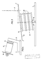
- the axis of the output shaft of the motor 17, and therefore the longitudinal axis of a glass 13 in the chuck 1, is disposed at a small angle x to the vertical, when viewed radially inwardly from the outer end of the arm 2.
- This angle x is shown in Figure 3 and may have a value of, for example, 1 degree.
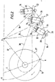
- the arcuate path that is followed by the centre of the chuck 1, during rotation of the arm 2 about the axis of the pillar 3, is indicated in Figure 2 by the reference 18.
- the starting point of the path 18 is referenced A, and the longitudinal axis of the pillar 3 is referenced 0, in Figure 2.
- the arcuate path 18 may end at an end point disposed diametrically opposite point A.
- a main grinding station 19 Disposed below the path 18 are a main grinding station 19, a secondary grinding station 20, and first and second polishing stations 21 and 22 respectively.
- the main grinding station 19 comprises a resilient backing disc 23 (e.g. of thin steel), mounted for rotation at one end of a pulley 24, which in turn is mounted on the drive shaft 25 of a drive motor 26.
- a flexible grinding disc 27 (e.g. of 180 grit) is mounted on the backing disc 23.
- the pulley 24 has three identical pulley sections 28.
- the axis of the pulley 24 is disposed at an angle of 6 degrees to the vertical, such that the backing disc 23 and grinding disc 27 are disposed at an angle of 6 degrees to the horizontal.
- the lowest and highest points of the working surface of the disc 27 are indicated by the references L and H respectively.
- the line passing through L,H subtends an angle of about 70 degrees with the line AO.
- the secondary grinding station 20 and the two polishing stations 21,22 are of similar construction.
- Each comprises a resilient grinding or polishing disc 29, 30, 31, mounted for rotation at an end of a respective shaft 32.
- the discs 29,30,31 may be of 180, 600 and 1200 grit, respectively.
- Each shaft 32 is mounted for rotation on a respective body 33, with the longitudinal axis of the shaft 32 disposed at an angle of 14 degrees to the horizontal.
- Each shaft 32 is formed with a pulley portion 34, at its inner end.
- each shaft 32 makes an angle of approximately 38 degrees with the respective radial line 36 that extends from the axis O of the pillar 3 to the centre of the respective disc 29, 30 or 31.
- the radial lines 36 are mutually spaced by angular intervals of about 20 degrees.
- the radial line 36 of the secondary grinding station 20 subtends an angle of about 60 degrees with the radial line 37 that extends from the axis O of the pillar 3 to the centre of the grinding disc 27 of the main grinding station 19.
- the radial line 37 may subtend an angle of about 40 degrees with the line AO.
- a light flexible drive belt 38 extends from each of the pulley portions 28 to a respective one of the pulley portions 34. In the interests of clarity, only one such drive belt is shown in Figure 2.
- a drain point 39 is formed in the plinth 4, and communicates with a tank 40, for lubricant or coolant fluid. Fluid from the tank is pumped by means of a pump 41 to a discharge nozzle 42 which is mounted on the arm 2, and is adapted to discharge fluid over the glass 13 in the chuck 1.
- a valve 75 diverts fluid to both the discharge nozzle 42 and a spray head 76, which is operative to spray fluid throughout an enclosure 80, in which the illustrated apparatus is housed.
- the enclosure 80 provides a sealed housing, which prevents the escape of any fluid, during operation of the apparatus.
- the parts 8 to 13, shown in a roundal in Figure 1, need not be disposed within the enclosure 80.
- the tank 40 is a disposable tank - e.g. of a plastics material, and has a bung 77 through which pass the pipes leading from the drain point 39 and to the pump 41.
- the fluid 78 within the tank 40 contains particles, which settle as a sediment 79.
- the spray device 76 there may be provided means for creating a forced down draught of air throughout the enclosure 80, to entrain any particles of glass, etc in the air flow.
- the air may then be bubbled through a tank such as the tank 40, to deposite particles therein, and thereby filter the air, which is subsequently recirculated.
- the illustrated apparatus operates as follows.
- the glass 13, having a chipped rim is placed on the table 11.
- the fingers 9,10 are placed on a level with the top of the rim of the glass 13, and a first measurement value recorded by the sensor 12 and control means 7.
- the fingers 9, 10 are then placed on a level just below the chipping on the rim, and a second measurement value recorded by the sensor 12 and control means 7.
- the control means determines the height setting of the pillar 3, and therefore the height setting of the chuck 1, corresponding to the amount of grinding required. (In practice, more than one pass may be required for a very deep chip, but it will be assumed for present purposes that this is not the case.) just below the chipping on the rim, and a second measurement value recorded by the sensor 12 and control means 7.
- the control means determines the height setting of the pillar 3, and therefore the height setting of the chuck 1, corresponding to the amount of grinding required. (In practice, more than one pass may be required for a very deep chip, but it will be assumed for present purposes that this is not the case.)
- the glass 13 is then inverted and placed in the chuck 1, as illustrated in Figure 1, where it is gripped by the self-centering jaws 15.
- the drive motor 17 is actuated to spin the glass 13 in the chuck 1 at a speed of, for example, 120 rpm, and the pump 41 is actuated, to commence a flow of coolant through the nozzle 42 and over the spinning glass 13.
- the pillar 3 is then caused to pivot slowly around its axis O, from the start position A, towards the main grinding station 19.
- the axis of the spinning glass follows substantially the path 18.
- the drive motor is actuated to spin the grinding disc at about 3000 rpm, and the grinding and polishing stations 20, 21 and 22 each at about 9000 rpm.
- the rim of the spinning glass 13 comes into contact with the working surface of the grinding disc 27, which commences to grind the rim of the glass. Grinding continues until the rim of the glass 13 pases over the highest point H of the disc 27, at which point the required amount of rim has been ground away.
- the chuck 1 may travel between the points A and H on the path 18 in about 4 minutes.
- the rim of the spinning glass 13 progressively contacts the grinding and polishing discs 20, 21, 22.
- the secondary polishing station 20 is so arranged that the rim of the glass 13 meets the grinding disc 29 between the centre of the disc 29 and its highest point. Also, because of its shape, the rim of the glass 13 first contacts the grinding disc somewhat radially inwardly of the centre of the disc 29. This has the effect of deflecting the disc 29 backwards (i.e. towards the radially inner end of the shaft 32), whilst the glass 13 passes over the grinding station 20. Initially, the grinding disc 29 works on the outer edge of the glass rim, thereby to shape a bevel on, or to round off, the rim. As the glass continues its travel, the inner edge of its rim meets the grinding disc 29, which therefore then works on the inner edge, to bevel or round off the rim further.
- the glass 13 continues its travel further along the path 18, it passes over the polishing stations 21 and 22, where the respective polishing discs 30 and 31 work on the rim of the glass 13, to finish off the bevelled or rounded edge.
- the centre of the first polishing disc 30 is slightly (e.g. 2 mm) higher than that of the grinding disc 29.
- the centre of the second polishing disc 31 is slightly (e.g. 2 mm) higher than that of the first polishing disc 30.
- the pillar 3 continues to rotate until the chuck 1 reaches its final position, diametrically opposite the starting point A. Then, the drive motors 17 and 26 and the pump 41 stop, and the glass 13 may be removed from the chuck 1. Prior to this, final rinsing and hot air drying operations may be carried out, if desired.
- the chuck 1 After the chuck 1 has passed the point H, its speed may be increased automatically, such that it completes the remainder of its travel to its end point in about 2 minutes. Means may be provided for manually adjusting the speed of arcuate travel of the chuck 1.
- the enclosure 80 is preferably fluid-tight and non-vented. It may be at least partially transparent, so that operation of the apparatus may be monitored visually. It will be appreciated that, during operation of the apparatus, small particles of glass will be ground away, and these will typically have a lead content.
- the enclosure 80 is continually flushed by means of the fluid which is sprayed or atomized by the spray head 76, and continually circulated by the pump 41, through the tank 40. The fluid spray thus entrains particles of glass or any other material, and these are carried down to the tank 40, where they progressively settle as the sediment 79.
- the interior walls of the enclosure 80 are preferably flush (with no hinges, etc protruding therefrom), to assist rinsing thereof by the fluid spray. Water may be conveniently used as the fluid, and may incorporate a wetting agent, so as to reduce surface tension and reduce the tendency for drops of fluid to remain on the interior walls of the enclosure. Also, use of a wetting agent will help to keep clean the glass 13 under repair.
- the removeable tank 40 may be taken away, disposed of without risk of pollution, and replaced by another tank.
- the closed fluid circuit provides a further practical advantage, in that the illustrated apparatus may be made truly portable, requiring (for example) only a 13 amp power outlet, to provide power for the electric motors.
- the coolant circuit may include suitable filters, for the removal of particles. However, to avoid blocking of any part of the system, it may be preferred to dispense with filters. A rust inhibitor may be added to the coolant fluid. Instead of the separate pump 41, there may be provided a submersible pump within the tank 40.
- the enclosure preferably has a door which is provided with an interlock device, to ensure operation of the apparatus only when the door is closed.
- the backing plate 23 of the main grinding station 19 is preferably of a spring steel. Grinding on the working surface of the disc 27 preferably starts somewhat radially inward from the circumference, to avoid undue wear, but radially outward of the centre, to avoid any fixing nut of the backing plate 23, and to achieve significant resilience of the backing plate 23.
- each disc 29, 30 and 31 may be disposed another two identical discs, so that each thus-formed combination of three discs exhibits an appropriate degree of flexibility and resilience. This is particularly convenient where each disc 29, 30 and 31 is cut from regular wet-and-dry abrasive paper.
- each disc 29, 30 and 31 may be of an appropriately thicker paper or backing material, or provided with its own resilient backing disc.
- the discs 29, 30 and 31 generally exhibit markedly more resilience than the main grinding disc 27 on its backing plate 23.
- the main grinding disc 27 may also conveniently be cut from regular wet-and-dry abrasive paper. If desired, concentric circles of abrasive material may be mounted on the plate 23 - e.g. a coarser grit paper disposed concentrically within a finer grit paper - so that graded grinding occurs at the main grinding station.
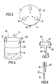
- one of a plurality of adapters such as the adaptor 50 of Figure 6 may be employed.
- the adapter 50 comprises a collar 53 of resilient material (e.g. rubber) which fits closely around the base of a crystal tumbler 54.
- Flexible straps 51 extend from the collar 53 at 120 degree intervals, and each strap 51 is formed with a respective hole 52.
- the adapter 50 enables stemless tumblers to be ground and polished in just the same way as stemmed glasses. Different sized adapters such as 50 are provided, for different sizes of tumblers.
- FIG. 6 An alternative adapter 60 is shown in Figures 6 and 7, and comprises three rubber straps 61 which are formed with holes 62, and are formed with loops 64 which engage around a rubber band 63.
- the adapter 60 is used in a manner very similar to the adapter 50, but is particularly simple to manufacture, and, for a given dimension of the rubber straps 61 and rubber band 63, may provide improved accomodation for tumblers of somewhat differing dimensions and configurations.
- the straps 61 may be provided with "VELCRO" (Registered Trade Mark) fastenings to secure together the respective parts of the straps 61 to form the loops 64.
- the straps 61 may be secured directly to the rubber band 63 by means of a "VELCRO" (Registered Trade Mark) or other releasable or non-releasable fastening means.
- the illustrated apparatus may be modified to grind the base of a stemmed glass, rather than the rim.
- the bases of glasses are equally as susceptible to chipping as the rims, and repair of a chipped base is often desirable.
- a glass such as the glass 13 is again gripped in the chuck 1, but this time in the opposite orientation to that illustrated in Figure 1 - namely upright.
- the arm 2 may be moved angularly to bring the base of the spinning glass 13 into contact with a substantially vertical grinding disc, similar to the grinding disc 27 on its resilient backing plate 23.
- the angular displacement of the arm 2 is accurately controlled, to achieve a desired amount of grinding of the glass base.
- the arm 2 may be moved to subsequent grinding and/or polishing stations.
- These may be, for example, similar to the stations 20, 21 and 22, but with the grinding and polishing discs inclined at different angles to the horizontal, so as to provide a rounded or bevelled finish to the edge of the glass base.
- the grinding and polishing discs may be disposed at a much smaller angle to the horizontal, and/or may be provided above and below the level of the path of travel of the glass base, so as to work on the upper and lower faces thereof.
- each of the shafts 32 may be eccentrically mounted on its respective body 33.
- Figures 9 and 10 show one example of an eccentric spindle 85, upon which each of the shafts 32 may be mounted.
- the spindle 85 has a first portion 86 which is arranged to be secured to a respective one of the bodies 33.
- a second spindle portion 87 extends from the first portion 86 and, as may be seen in Figures 9 and 10, is disposed eccentrically thereof.
- each of the jaws 91 comprises a base portion 92 of rectangular cross-section, and a jaw member 93, which is also of rectangular cross-section.
- each jaw member 94 has a substantially planar face, to contact the base of a glass.
- each jaw 91 may be of steel, and each jaw member 93 may be detachably secured thereto.
- the jaw members 93 may be of a plastics material, and may be interchangeable with jaw members of differing shape and/or size.
- a jaw 95 is similar to that shown in Figure 12, but has a jaw member 96 of a different shape, defining a relatively large acute angle x, to assist retaining the base of a glass.
- the contact face 97 of the jaw member 96 is provided with a material of relatively high coefficient of friction, to improve grip.
Landscapes
- Engineering & Computer Science (AREA)
- Mechanical Engineering (AREA)
- Chemical & Material Sciences (AREA)
- Ceramic Engineering (AREA)
- Inorganic Chemistry (AREA)
- Grinding And Polishing Of Tertiary Curved Surfaces And Surfaces With Complex Shapes (AREA)
Applications Claiming Priority (2)
| Application Number | Priority Date | Filing Date | Title |
|---|---|---|---|
| GB858531727A GB8531727D0 (en) | 1985-12-24 | 1985-12-24 | Glassware grinding/polishing apparatus |
| GB8531727 | 1985-12-24 |
Publications (1)
| Publication Number | Publication Date |
|---|---|
| EP0230785A1 true EP0230785A1 (de) | 1987-08-05 |
Family
ID=10590238
Family Applications (1)
| Application Number | Title | Priority Date | Filing Date |
|---|---|---|---|
| EP86310144A Withdrawn EP0230785A1 (de) | 1985-12-24 | 1986-12-24 | Schleif- und/oder Poliervorrichtung für Glaswaren |
Country Status (3)
| Country | Link |
|---|---|
| US (1) | US4872290A (de) |
| EP (1) | EP0230785A1 (de) |
| GB (2) | GB8531727D0 (de) |
Families Citing this family (4)
| Publication number | Priority date | Publication date | Assignee | Title |
|---|---|---|---|---|
| BE1002045A4 (fr) * | 1988-05-26 | 1990-06-05 | Biebuyck Sa Ets | Procede de tronconnage-flettage combines a l'aide d'outils abrasifs d'articles de verrerie ou de cristallerie et dispositif mettant en oeuvre le procede. |
| USD338474S (en) | 1992-04-06 | 1993-08-17 | Christensen Donald E | Porcelain sander |
| US5700181A (en) * | 1993-09-24 | 1997-12-23 | Eastman Kodak Company | Abrasive-liquid polishing and compensating nozzle |
| CN116475891B (zh) * | 2023-05-23 | 2023-12-19 | 江苏欣鼎包装科技股份有限公司 | 玻璃瓶表面处理设备 |
Citations (7)
| Publication number | Priority date | Publication date | Assignee | Title |
|---|---|---|---|---|
| DD20271A (de) * | ||||
| CH182476A (fr) * | 1935-03-21 | 1936-02-15 | Rossier Mery | Procédé pour rectifier le bord circulaire ébréché d'un ustensile en verre, et installation pour la mise en oeuvre de ce procédé. |
| CH285549A (fr) * | 1949-12-21 | 1952-09-15 | Junod Jean Pierre | Procédé pour rectifier les verres à boire ébréchés et installation pour la mise en oeuvre de ce procédé. |
| DE2450025A1 (de) * | 1973-11-05 | 1975-05-07 | Corning Glass Works | Transport- und schleifvorrichtung fuer fernsehroehren |
| DE2700487B2 (de) * | 1977-01-07 | 1980-07-31 | Emil 8372 Zwiesel Ilk | Abspreng- und Schleifautomat für Gläser |
| DD209994A1 (de) * | 1982-09-21 | 1984-05-30 | Werkzeugmasch Okt Veb | Schleifhilfsstoffabsaugeeinrichtung fuer schleifmaschinen |
| GB2147530A (en) * | 1983-08-19 | 1985-05-15 | Abbeybench Ltd | Glassware grinding & polishing apparatus |
Family Cites Families (3)
| Publication number | Priority date | Publication date | Assignee | Title |
|---|---|---|---|---|
| US880188A (en) * | 1907-12-09 | 1908-02-25 | American Cutlery Company | Grinding-machine. |
| US1388231A (en) * | 1920-03-26 | 1921-08-23 | Abraham Lewis | Polisher and grinder for wood and metal manufacturers |
| GB1463302A (en) * | 1973-08-09 | 1977-02-02 | Glass Tubes & Components Ltd | Self-centering chuck |
-
1985
- 1985-12-24 GB GB858531727A patent/GB8531727D0/en active Pending
-
1986
- 1986-12-24 US US06/946,450 patent/US4872290A/en not_active Expired - Fee Related
- 1986-12-24 EP EP86310144A patent/EP0230785A1/de not_active Withdrawn
- 1986-12-24 GB GB8630902A patent/GB2185202B/en not_active Expired - Fee Related
Patent Citations (7)
| Publication number | Priority date | Publication date | Assignee | Title |
|---|---|---|---|---|
| DD20271A (de) * | ||||
| CH182476A (fr) * | 1935-03-21 | 1936-02-15 | Rossier Mery | Procédé pour rectifier le bord circulaire ébréché d'un ustensile en verre, et installation pour la mise en oeuvre de ce procédé. |
| CH285549A (fr) * | 1949-12-21 | 1952-09-15 | Junod Jean Pierre | Procédé pour rectifier les verres à boire ébréchés et installation pour la mise en oeuvre de ce procédé. |
| DE2450025A1 (de) * | 1973-11-05 | 1975-05-07 | Corning Glass Works | Transport- und schleifvorrichtung fuer fernsehroehren |
| DE2700487B2 (de) * | 1977-01-07 | 1980-07-31 | Emil 8372 Zwiesel Ilk | Abspreng- und Schleifautomat für Gläser |
| DD209994A1 (de) * | 1982-09-21 | 1984-05-30 | Werkzeugmasch Okt Veb | Schleifhilfsstoffabsaugeeinrichtung fuer schleifmaschinen |
| GB2147530A (en) * | 1983-08-19 | 1985-05-15 | Abbeybench Ltd | Glassware grinding & polishing apparatus |
Non-Patent Citations (1)
| Title |
|---|
| SOVIET INVENTIONS ILLUSTRATED, Section Mechanical, Week 8508, 3th April 1985, abstract no. 049111, P61, Derwent Publications LTD., London, GB.; & SU - A - 1 103 995 (ODESS BR GLASS EQIPT) 23-07-1984 * |
Also Published As
| Publication number | Publication date |
|---|---|
| GB8630902D0 (en) | 1987-02-04 |
| GB2185202A (en) | 1987-07-15 |
| GB8531727D0 (en) | 1986-02-05 |
| GB2185202B (en) | 1990-05-30 |
| US4872290A (en) | 1989-10-10 |
Similar Documents
| Publication | Publication Date | Title |
|---|---|---|
| CA1215841A (en) | Wet surface treating device and element therefor | |
| JPH0375302B2 (de) | ||
| CN101500752A (zh) | 砂光工具 | |
| US4872290A (en) | Glassware grinding and/or polishing apparatus | |
| US5548860A (en) | Ultra-speed conversion means for floor treating machines | |
| JPS5871053A (ja) | 円筒容器の研磨装置 | |
| CN115647944A (zh) | 一种磨切刀具卷刃用刃口重塑装置及其实施方法 | |
| CN209754896U (zh) | 一种磨床 | |
| CN211490885U (zh) | 一种便于除尘的玻璃瓶塞磨口机 | |
| CN207840906U (zh) | 一种建筑用打磨机 | |
| CA2333521A1 (en) | Planar/grinder for glass | |
| KR101167922B1 (ko) | 공압형 오비탈 샌더 | |
| CN217194373U (zh) | 一种方便收集废屑的自动圆管毛刺去锈抛光机 | |
| CN217255167U (zh) | 一种玻璃加工用磨边装置 | |
| CN211219989U (zh) | 一种多功能驱动型去毛刺机构 | |
| JP4336466B2 (ja) | 加工具洗浄装置 | |
| CN211277938U (zh) | 一种自动端面磨床 | |
| CN223289552U (zh) | 一种智能锁配件磁力抛光装置 | |
| CN208788341U (zh) | 抛丸镜面研磨机 | |
| CN217019714U (zh) | 一种打磨清理装置 | |
| CN215317762U (zh) | 阀门龙头表面打磨设备 | |
| CN223917510U (zh) | 一种塑料餐具加工用的磨边装置 | |
| CN213409677U (zh) | 一种五金件的表面自动抛光设备 | |
| US2537625A (en) | Wheel polishing machine | |
| US4058869A (en) | Scrubbing apparatus for pottery greenware |
Legal Events
| Date | Code | Title | Description |
|---|---|---|---|
| PUAI | Public reference made under article 153(3) epc to a published international application that has entered the european phase |
Free format text: ORIGINAL CODE: 0009012 |
|
| AK | Designated contracting states |
Kind code of ref document: A1 Designated state(s): AT BE CH DE ES FR GB GR IT LI LU NL SE |
|
| 17P | Request for examination filed |
Effective date: 19880114 |
|
| 17Q | First examination report despatched |
Effective date: 19890413 |
|
| STAA | Information on the status of an ep patent application or granted ep patent |
Free format text: STATUS: THE APPLICATION IS DEEMED TO BE WITHDRAWN |
|
| 18D | Application deemed to be withdrawn |
Effective date: 19901024 |
|
| RIN1 | Information on inventor provided before grant (corrected) |
Inventor name: JENKINSON, MARGARET Inventor name: DUNNE, JOHN |