EP0230814A1 - Seilstützenanordnung und Seilschwebebahn mit derartiger Anordnung - Google Patents
Seilstützenanordnung und Seilschwebebahn mit derartiger Anordnung Download PDFInfo
- Publication number
- EP0230814A1 EP0230814A1 EP86402766A EP86402766A EP0230814A1 EP 0230814 A1 EP0230814 A1 EP 0230814A1 EP 86402766 A EP86402766 A EP 86402766A EP 86402766 A EP86402766 A EP 86402766A EP 0230814 A1 EP0230814 A1 EP 0230814A1
- Authority
- EP
- European Patent Office
- Prior art keywords
- pendulums
- cables
- elementary
- support
- pivoting
- Prior art date
- Legal status (The legal status is an assumption and is not a legal conclusion. Google has not performed a legal analysis and makes no representation as to the accuracy of the status listed.)
- Granted
Links
- 238000009434 installation Methods 0.000 claims description 8
- 230000000903 blocking effect Effects 0.000 claims 1
- XEEYBQQBJWHFJM-UHFFFAOYSA-N Iron Chemical compound [Fe] XEEYBQQBJWHFJM-UHFFFAOYSA-N 0.000 description 2
- 230000000712 assembly Effects 0.000 description 1
- 238000000429 assembly Methods 0.000 description 1
- 230000006835 compression Effects 0.000 description 1
- 238000007906 compression Methods 0.000 description 1
- 238000013016 damping Methods 0.000 description 1
- 229910052742 iron Inorganic materials 0.000 description 1
- 238000012423 maintenance Methods 0.000 description 1
Images
Classifications
-
- B—PERFORMING OPERATIONS; TRANSPORTING
- B61—RAILWAYS
- B61B—RAILWAY SYSTEMS; EQUIPMENT THEREFOR NOT OTHERWISE PROVIDED FOR
- B61B12/00—Component parts, details or accessories not provided for in groups B61B7/00 - B61B11/00
- B61B12/02—Suspension of the load; Guiding means, e.g. wheels; Attaching traction cables
Definitions
- the invention relates to a cable holding device and installation for overhead cable transport comprising such a device.
- the main constructive characteristic of this known device is that on the one hand the spacing of the rollers corresponding to the two cables and kept positively constant and equal to the spacing of the cables and that, on the other hand, the overall pivoting movements rollers (around the pivoting axis of the flat bars) corresponding to the two cables are made positively in perfect synchronism, that is to say that a symmetrical pivoting of the pendulums is imposed.
- This positive maintenance of the spacing and of the synchonism as well as of the symmetry of the pivoting is obtained thanks to the rigid stirrup joining in a monobloc and undeformable assembly the rollers (or more precisely their axes of rotation) located in correspondence and associated with the two cables.
- the bracket Given the passage to be left free between the cables for the carriage or the like carrying the vehicle, the bracket has a general shape of an inverted U.
- This known structure responds to the concern to ensure symmetry and perfect synchronism between the two cables and therefore the members associated with them. If from a theoretical point of view this concern seems legitimate, it is not the same from a practical point of view.
- these parameters can, in practice, vary widely from one cable to another on the same cross section, if only because the cable paths are distinct from each other (the paths being generally possibly uneven) with all the consequences which result therefrom. Under these conditions, maintaining synchronism or symmetry of movement between the pendulums or the rollers can in fact prove to be a particularly inconvenient drawback insofar as it generates additional stresses in the cable holding device.
- the invention aims to remedy these drawbacks and for this purpose it proposes a device for holding cables of the type comprising, for each of the cables, one or more elementary pendulums furnished with at least one roller with which the corresponding cable cooperates, this elementary pendulum being pivotally mounted about an axis orthogonal to the cables on support pendulums themselves carried by a bearing structure, the elementary pendulums, rollers, pendulums supporting the various cables being placed facing each other, characterized in that the elementary pendulums in correspondence associated with the different cables are not mechanically connected together in order to form a one-piece assembly such that their symmetrical pivoting is imposed.
- the device comprises means limiting the amplitude of the pivoting of the elementary pendulums around their pivot axis as well as means limiting the amplitude of the pivoting of the support pendulums around their pivot axis.
- the invention aims to avoid completely subjecting each other the rollers associated with the different cables. These pebbles have a certain freedom in their overall movements. However, this reciprocal travel is limited. Consequently, the stresses on the cables or their holding devices are better distributed.
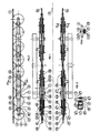
- the invention relates to a cable holding device 1 intended in particular for an overhead cable transport installation - in particular two parallel or substantially parallel carrying cables and tractors 1a, 1b.
- the device has an overall symmetry with respect to a median plane P.
- This plane is generally a vertical plane in the case of an overhead cable transport installation.
- the device will be described in its generality without referring specifically to one cable or another, the corresponding reference then being devoid of index.
- the corresponding reference will be followed by the index a or b, respectively.
- the device comprises, for each of the cables 1, one or more generally several elementary pendulums 2 furnished with at least one roller 3 pivoting about its axis 4 and with which the corresponding cable 1 cooperates.
- This elementary pendulum 2 is pivotally mounted around an axis 5 orthogonal to the cables 1 on support pendulums 6 themselves carried by a bearing structure 7.
- the elementary pendulums 2, rollers 3, axis 4, axis 5, support pendulums 6, and components of the supporting structure 7 associated with the various cables 1, are placed facing each other since they are placed as a whole symmetrically with respect to the plane P.
- the support pendulum 6 is also pivotally mounted on the supporting structure 7 around an axis 8 parallel to the axes 4 and 5.
- an elementary balance 2 of a cable 1 comprises two rollers 3 placed in close proximity to each other, the axes 4 of these rollers being located at the two end parts 9 of the elementary balance 2.
- a support pendulum 6 are associated with two elementary pendulums 2, the axes 5 being located at the end portions 10 of the support pendulum 6.
- the two closest rollers 3 associated with the two elementary pendulums 2 are placed in close proximity to one another.
- the supporting structure 7 associated with a cable 1 are associated with two support pendulums 6, the pins 8 being placed at the end portions 11 of this structure.
- the closest rollers of the two support pendulums 6 are also placed in the immediate vicinity of one another.
- the axes 5 and 8 are placed in the middle parts of the elementary balance 2 and of the support balance 6, respectively.
- the rollers 3 are normally identical and constituted by grooved pulleys.
- the invention applies to the case of an elementary balance 2 furnished with a different number of rollers 3, to the case of a support balance 6 furnished with a different number of elementary balance 2 and to the case of a bearing structure 7 furnished with a different number of support pendulums 6.
- the invention also applies to the case where the structure which has just been described (first pendulum mounted to pivot by its middle part to the end part of a second pendulum) and multiplied more significantly.
- the rollers 3 are either support rollers, when the cables 1 are located above, or compression rollers, when the cables 1 are located below.
- the supporting structure 7 is symmetrical with respect to the plane P, and external to the cable channel 1 and the rollers 3, the elementary pendulums 2, the supporting pendulums 6 are placed laterally, towards the outside of the supporting structure 7 therefore, or near or symmetrically on either side of the planes P A and P B parallel to the plane P and passing through the cables 1a, 1b respectively.
- the structure 7 is central (not shown).
- each elementary balance 2 associated with a cable 1 is in two parts 2 ⁇ , 2 ⁇ placed respectively on either side of the rollers 3.
- each balance associated with a cable 1 is also in two parts 6 ⁇ , 6 ⁇ , on either side of the rollers 3 and outside of the parts 2 ⁇ and 2 ⁇ of the elementary pendulums 2.
- the supporting structure 7 forms two lateral beams fixed to and carried by a super structure not shown in particular forming part of a pylon.
- Each axis 8 is fixed and extends on either side of the supporting structure 7 in the direction of the planes Pa and Pb.
- On the axis 8 are mounted the two parts 6 ⁇ and 6 ⁇ of a support pendulum 10 and this for each of the cables 1a, 1b.
- the two parts 6 ⁇ and 6 ⁇ are spaced transversely from one another to allow the housing between them of parts 2 ⁇ and 2 ⁇ of the two elementary pendulums 2 and of the rollers 3.
- the elementary pendulums 2 in correspondence associated with the different cables are not mechanically connected together in order to form a one-piece assembly such that their symmetrical pivoting is imposed. This absence of direct and rigid mechanical connection is clearly visible in FIG. 1.
- corresponding support pendulums 6 associated with the various cables are not mechanically connected together in order to form a one-piece assembly such as their pivoting symmetrical be imposed. This characteristic is also clearly visible in FIG. 1.
- means are provided limiting the amplitude of the pivoting of the elementary pendulums 2 around their pivot axis 5.
- means are provided limiting the amplitude of the pivoting of the elementary pendulums 2 around their pivot axis 5 at a value between 0 °, terminal excluded, and 10 °.
- These means limiting the amplitude of the pivoting of the elementary pendulums 2 about their axis 5 are constituted for example by a central part 12 associated with / or constituted by the elementary balance 2 or the support balance 6 cooperating with a double lateral part 13 forming a fork associated with / or constituted by the support pendulum 6 or the elementary balance 2.
- the central part 12 is constituted by one of the parts - in particular the internal part - of the pendulum 2 and the double lateral piece 13 and constituted by an insert on the support pendulum 6.
- This central piece 12 and double lateral piece 13 assembly is spaced from the axis 5 by a distance neither too great so that the amplitude pivoting is sufficient, nor too low so that this amplitude is not too large and this with a play of the central part 12 in the double part lateral 13 limited.
- the central part 12 and double lateral part 13 assembly is placed between the axis 5 of the elementary balance 2 and the axis 4 of one of the rollers 3 that it supports.
- the central part 12 and double lateral part 13 assembly is placed from the axis 5 at about a third of the distance separating the axis 5 from the axis 4.
- the clearance between the central part 12 and the part double lateral 13 is for example of the order of a few millimeters.
- part 12, part 13 assembly is provided for each elementary balance 2.
- this central part 12 and double lateral part 13 assembly is placed on the internal part of a pendulum 2, that is to say the part facing the bearing structure 7. Also, preferably, each central part assembly 12 , double side piece 13 is placed at the extended end part 14 of the internal part 6 ⁇ of the support balance 6.
- means are provided limiting the amplitude of the pivoting of the support pendulums 6 about their pivot axis 8. These means limit the pivoting for example to a value between 0 ° terminal excluded and 10 °. These means are constituted in particular by a central part 15 associated with / or constituted by the support pendulum 6 or the supporting structure 7 cooperating with a double lateral part 16 forming a fork associated with / or constituted by the bearing structure 7 or the support pendulum 6.
- the central part 15 is constituted by the support pendulum 6 in particular its internal part 6 ⁇ and the double lateral part 16 is constituted by an insert on the lateral face of the supporting structure 7 .
- the whole central piece 15 and double side piece 16 is sufficiently spaced without being too far from the pivot axis 8 of the support pendulum 6.
- the central piece 15, piece double lateral 15 is placed in the vicinity of the end of the support pendulum 6, in particular substantially symmetrical to the central part 12, lateral part 13 with respect to the axis 5.
- the support pendulums 6 are axially wedged on the axis 8 while being free to rotate about this axis (except for the presence of the means for limiting the pivoting 15, 16).
- Presence of end-of-travel damping means such as elastic stops; elastic means for returning to a middle position such as elastically deformable blocks; means for adjusting the amplitude either by sliding the assemblies 12, 13, 15, 16 respectively along the support pendulum 6 or along the supporting structure 7 or even by means of an adjustable stop.
- the invention also relates to an overhead cable transport installation, in particular two carrying cables and parallel tractors extending between end stations and supported by one or more holding devices such as the one just described, the cables themselves supporting one or more vehicles.
Landscapes
- Engineering & Computer Science (AREA)
- Transportation (AREA)
- Mechanical Engineering (AREA)
- Electric Cable Installation (AREA)
- Storing, Repeated Paying-Out, And Re-Storing Of Elongated Articles (AREA)
- Supports For Pipes And Cables (AREA)
- Laying Of Electric Cables Or Lines Outside (AREA)
- Vibration Prevention Devices (AREA)
- Lift-Guide Devices, And Elevator Ropes And Cables (AREA)
Priority Applications (1)
| Application Number | Priority Date | Filing Date | Title |
|---|---|---|---|
| AT86402766T ATE56923T1 (de) | 1985-12-11 | 1986-12-11 | Seilstuetzenanordnung und seilschwebebahn mit derartiger anordnung. |
Applications Claiming Priority (2)
| Application Number | Priority Date | Filing Date | Title |
|---|---|---|---|
| FR8518333A FR2591173B1 (fr) | 1985-12-11 | 1985-12-11 | Dispositif de maintien de cables et installation de transport a cables aeriens comportant un tel dispositif |
| FR8518333 | 1985-12-11 |
Publications (2)
| Publication Number | Publication Date |
|---|---|
| EP0230814A1 true EP0230814A1 (de) | 1987-08-05 |
| EP0230814B1 EP0230814B1 (de) | 1990-09-26 |
Family
ID=9325673
Family Applications (1)
| Application Number | Title | Priority Date | Filing Date |
|---|---|---|---|
| EP86402766A Expired - Lifetime EP0230814B1 (de) | 1985-12-11 | 1986-12-11 | Seilstützenanordnung und Seilschwebebahn mit derartiger Anordnung |
Country Status (7)
| Country | Link |
|---|---|
| US (1) | US4777886A (de) |
| EP (1) | EP0230814B1 (de) |
| JP (1) | JP2667165B2 (de) |
| AT (1) | ATE56923T1 (de) |
| CA (1) | CA1284122C (de) |
| DE (1) | DE3674571D1 (de) |
| FR (1) | FR2591173B1 (de) |
Cited By (3)
| Publication number | Priority date | Publication date | Assignee | Title |
|---|---|---|---|---|
| FR2892371A1 (fr) * | 2005-10-24 | 2007-04-27 | Pomagalski Sa | Balancier a galets pour l'appui et le guidage d'un cable aerien porteur-tracteur, et installation de remontee mecanique comportant un tel balancier |
| EP1918171A1 (de) | 2006-10-30 | 2008-05-07 | Pomagalski S.A. | Rollenbatterie zur Abstützung und Führung eines Trag-/Zugseils und mechanische Aufstiegsanlage mit solch einer Rollenbatterie |
| EP3530539A1 (de) * | 2018-02-26 | 2019-08-28 | Poma | Stütz- und führungsvorrichtung eines zugseils eines fahrzeugs einer transportanlage, gelenk einer solchen vorrichtung und herstellungsverfahren dieser vorrichtung |
Families Citing this family (3)
| Publication number | Priority date | Publication date | Assignee | Title |
|---|---|---|---|---|
| US4995319A (en) * | 1989-06-09 | 1991-02-26 | Poma Of America, Inc. | Sheave train assembly for cable transportation systems |
| AT517045B1 (de) * | 2015-04-14 | 2018-06-15 | Kurt Wopfner | Lagerbock zur Lagerung einer Rollenbatterie |
| FR3074467B1 (fr) * | 2017-12-04 | 2021-12-17 | Poma | Dispositif d'appui et de guidage d'un cable tracteur d'une installation de transport de vehicule et procede de controle d'un tel dispositif |
Citations (4)
| Publication number | Priority date | Publication date | Assignee | Title |
|---|---|---|---|---|
| DE2241979A1 (de) * | 1972-08-25 | 1974-03-14 | Paul Dipl Ing Morsbach | Seilbahn |
| EP0086084A2 (de) * | 1982-02-05 | 1983-08-17 | KUNCZYNSKI, Jan Krzysztof | Kabelschwingstützen für Kabelbahnpfeiler |
| EP0093680A1 (de) * | 1982-04-28 | 1983-11-09 | Denis Creissels | Kabinenbahn mit zwei Trage- und Zugkabeln |
| EP0163555A1 (de) * | 1984-04-13 | 1985-12-04 | Pomagalski S.A. | Rollenschwinge für eine Kabelbahn-Transporteinrichtung |
Family Cites Families (3)
| Publication number | Priority date | Publication date | Assignee | Title |
|---|---|---|---|---|
| US347443A (en) * | 1886-08-17 | peaece eoe and peteb boe bedlington | ||
| FR2207478A5 (de) * | 1972-11-20 | 1974-06-14 | Pomagalski Sa | |
| US4509430A (en) * | 1983-06-06 | 1985-04-09 | Creissels Denis C | Twin suspension/haulage cable gondola lift |
-
1985
- 1985-12-11 FR FR8518333A patent/FR2591173B1/fr not_active Expired
-
1986
- 1986-12-10 CA CA000524941A patent/CA1284122C/fr not_active Expired - Lifetime
- 1986-12-11 AT AT86402766T patent/ATE56923T1/de not_active IP Right Cessation
- 1986-12-11 DE DE8686402766T patent/DE3674571D1/de not_active Expired - Lifetime
- 1986-12-11 EP EP86402766A patent/EP0230814B1/de not_active Expired - Lifetime
- 1986-12-11 JP JP29568186A patent/JP2667165B2/ja not_active Expired - Lifetime
- 1986-12-11 US US06/940,586 patent/US4777886A/en not_active Expired - Fee Related
Patent Citations (4)
| Publication number | Priority date | Publication date | Assignee | Title |
|---|---|---|---|---|
| DE2241979A1 (de) * | 1972-08-25 | 1974-03-14 | Paul Dipl Ing Morsbach | Seilbahn |
| EP0086084A2 (de) * | 1982-02-05 | 1983-08-17 | KUNCZYNSKI, Jan Krzysztof | Kabelschwingstützen für Kabelbahnpfeiler |
| EP0093680A1 (de) * | 1982-04-28 | 1983-11-09 | Denis Creissels | Kabinenbahn mit zwei Trage- und Zugkabeln |
| EP0163555A1 (de) * | 1984-04-13 | 1985-12-04 | Pomagalski S.A. | Rollenschwinge für eine Kabelbahn-Transporteinrichtung |
Cited By (6)
| Publication number | Priority date | Publication date | Assignee | Title |
|---|---|---|---|---|
| FR2892371A1 (fr) * | 2005-10-24 | 2007-04-27 | Pomagalski Sa | Balancier a galets pour l'appui et le guidage d'un cable aerien porteur-tracteur, et installation de remontee mecanique comportant un tel balancier |
| EP1918171A1 (de) | 2006-10-30 | 2008-05-07 | Pomagalski S.A. | Rollenbatterie zur Abstützung und Führung eines Trag-/Zugseils und mechanische Aufstiegsanlage mit solch einer Rollenbatterie |
| EP3530539A1 (de) * | 2018-02-26 | 2019-08-28 | Poma | Stütz- und führungsvorrichtung eines zugseils eines fahrzeugs einer transportanlage, gelenk einer solchen vorrichtung und herstellungsverfahren dieser vorrichtung |
| FR3078309A1 (fr) * | 2018-02-26 | 2019-08-30 | Poma | Dispositif d'appui et de guidage d'un cable tracteur de vehicule d'une installation de transport, articulation d'un tel dispositif et procede de fabrication du dispositif |
| CN110194184A (zh) * | 2018-02-26 | 2019-09-03 | 波马公司 | 用于运输设备的车辆牵引缆线的支撑和引导装置的铰接件 |
| US11230299B2 (en) | 2018-02-26 | 2022-01-25 | Poma | Device for supporting and guiding a vehicle hauling cable of a transport installation, articulation of such a device and method of manufacturing the device |
Also Published As
| Publication number | Publication date |
|---|---|
| EP0230814B1 (de) | 1990-09-26 |
| DE3674571D1 (de) | 1990-10-31 |
| CA1284122C (fr) | 1991-05-14 |
| ATE56923T1 (de) | 1990-10-15 |
| US4777886A (en) | 1988-10-18 |
| FR2591173B1 (fr) | 1988-10-21 |
| JPS62196003A (ja) | 1987-08-29 |
| JP2667165B2 (ja) | 1997-10-27 |
| FR2591173A1 (fr) | 1987-06-12 |
Similar Documents
| Publication | Publication Date | Title |
|---|---|---|
| EP0093680B1 (de) | Kabinenbahn mit zwei Trage- und Zugkabeln | |
| EP0464078A1 (de) | Drehgestell mit verformbarem rahmen sowie verfahren und teilesatz zur verbesserung eines solchen drehgestells | |
| EP0230814B1 (de) | Seilstützenanordnung und Seilschwebebahn mit derartiger Anordnung | |
| CA1196818A (fr) | Dispositif de suspension et de liaison entre un chassis de bogie et une boite d'essieu | |
| EP2683562A1 (de) | Vorrichtung zur befestigung eines fahrzeugrades an einer kraftfahrzeugstruktur | |
| EP3222485B1 (de) | Schienenfahrzeugdrehgestell, das eine versetzte primäre federungsvorrichtung umfasst | |
| EP0187552A1 (de) | Seilschwebebahn | |
| FR2573013A1 (fr) | Dispositifs de liaison pour une lame elastique de suspension d'un vehicule et procede de mise en place desdits dispositifs | |
| EP1247714A1 (de) | Drehgestell für Schienenfahrzeuge mit Rädern mit verstellbarer Spurweite | |
| FR3035028A1 (fr) | "ensemble de train arriere roulant integrant un moteur semi-porteur pour vehicule automobile" | |
| FR2586624A1 (fr) | Dispositifs assurant le guidage et la suspension des trains (avant ou arriere) de vehicules | |
| EP0444973B1 (de) | Scherenstromabnehmer mit zwei konjugierten Köpfen eines schienengebundenen Triebfahrzeuges | |
| EP0277059B1 (de) | Schienenfahrzeug mit Lastverteilung auf die vier bezüglich des Aufbaus einstellbaren Achsen | |
| FR2604138A1 (fr) | Dispositif de maintien en ligne au droit d'un pylone de cables aeriens entraines a defilement, et installation de transport a cables aeriens comportant un tel dispositif | |
| CA1024824A (en) | Continuous variable speed control system for travelling railings | |
| EP0132721B1 (de) | Befestigungsvorrichtung für Sessellift oder Kabine an einem Kabel mit Rollenlauffläche | |
| FR2669318A1 (fr) | Transporteur a chariot tracte par un arbre tournant sur lui-meme. | |
| EP1712442B1 (de) | Vorrichtung zur Aufhängung eines Motors an einem Drehgestellrahmen | |
| EP3395640B1 (de) | Drehgestell eines schienenfahrzeugs, das ein bremssystem mit drei bremsscheiben umfasst, die zwischen den achsengehäusen angeordnet sind | |
| EP0556139B1 (de) | Seilbahn mit seitlich abgelenkten Kabeln | |
| FR2475467A1 (fr) | Support d'essieu de vehicule automobile | |
| EP3219571B1 (de) | Schienenfahrzeugdrehgestell, das ein bremssystem umfasst, und entsprechendes schienenfahrzeug | |
| FR2634720A1 (fr) | Suspension de roue arriere adaptable sur un cyclomoteur | |
| EP1918171B1 (de) | Rollenbatterie zur Abstützung und Führung eines Trag-/Zugseils und mechanische Aufstiegsanlage mit solch einer Rollenbatterie | |
| FR2782303A1 (fr) | Unite de frein a sabot pour vehicules sur rails |
Legal Events
| Date | Code | Title | Description |
|---|---|---|---|
| PUAI | Public reference made under article 153(3) epc to a published international application that has entered the european phase |
Free format text: ORIGINAL CODE: 0009012 |
|
| AK | Designated contracting states |
Kind code of ref document: A1 Designated state(s): AT CH DE FR GB IT LI SE |
|
| 17P | Request for examination filed |
Effective date: 19870921 |
|
| 17Q | First examination report despatched |
Effective date: 19881229 |
|
| GRAA | (expected) grant |
Free format text: ORIGINAL CODE: 0009210 |
|
| AK | Designated contracting states |
Kind code of ref document: B1 Designated state(s): AT CH DE FR GB IT LI SE |
|
| REF | Corresponds to: |
Ref document number: 56923 Country of ref document: AT Date of ref document: 19901015 Kind code of ref document: T |
|
| ITF | It: translation for a ep patent filed | ||
| REF | Corresponds to: |
Ref document number: 3674571 Country of ref document: DE Date of ref document: 19901031 |
|
| PGFP | Annual fee paid to national office [announced via postgrant information from national office to epo] |
Ref country code: FR Payment date: 19901123 Year of fee payment: 5 |
|
| GBT | Gb: translation of ep patent filed (gb section 77(6)(a)/1977) | ||
| PGFP | Annual fee paid to national office [announced via postgrant information from national office to epo] |
Ref country code: GB Payment date: 19901210 Year of fee payment: 5 |
|
| PGFP | Annual fee paid to national office [announced via postgrant information from national office to epo] |
Ref country code: AT Payment date: 19901214 Year of fee payment: 5 |
|
| PGFP | Annual fee paid to national office [announced via postgrant information from national office to epo] |
Ref country code: SE Payment date: 19901228 Year of fee payment: 5 |
|
| ITTA | It: last paid annual fee | ||
| PGFP | Annual fee paid to national office [announced via postgrant information from national office to epo] |
Ref country code: CH Payment date: 19910121 Year of fee payment: 5 |
|
| PGFP | Annual fee paid to national office [announced via postgrant information from national office to epo] |
Ref country code: DE Payment date: 19910131 Year of fee payment: 5 |
|
| PLBE | No opposition filed within time limit |
Free format text: ORIGINAL CODE: 0009261 |
|
| STAA | Information on the status of an ep patent application or granted ep patent |
Free format text: STATUS: NO OPPOSITION FILED WITHIN TIME LIMIT |
|
| 26N | No opposition filed | ||
| PG25 | Lapsed in a contracting state [announced via postgrant information from national office to epo] |
Ref country code: GB Effective date: 19911211 Ref country code: AT Effective date: 19911211 |
|
| PG25 | Lapsed in a contracting state [announced via postgrant information from national office to epo] |
Ref country code: SE Effective date: 19911212 |
|
| PG25 | Lapsed in a contracting state [announced via postgrant information from national office to epo] |
Ref country code: LI Effective date: 19911231 Ref country code: CH Effective date: 19911231 |
|
| GBPC | Gb: european patent ceased through non-payment of renewal fee | ||
| PG25 | Lapsed in a contracting state [announced via postgrant information from national office to epo] |
Ref country code: FR Effective date: 19920831 |
|
| REG | Reference to a national code |
Ref country code: CH Ref legal event code: PL |
|
| PG25 | Lapsed in a contracting state [announced via postgrant information from national office to epo] |
Ref country code: DE Effective date: 19920901 |
|
| REG | Reference to a national code |
Ref country code: FR Ref legal event code: ST |
|
| EUG | Se: european patent has lapsed |
Ref document number: 86402766.9 Effective date: 19920704 |
|
| PG25 | Lapsed in a contracting state [announced via postgrant information from national office to epo] |
Ref country code: IT Free format text: LAPSE BECAUSE OF NON-PAYMENT OF DUE FEES;WARNING: LAPSES OF ITALIAN PATENTS WITH EFFECTIVE DATE BEFORE 2007 MAY HAVE OCCURRED AT ANY TIME BEFORE 2007. THE CORRECT EFFECTIVE DATE MAY BE DIFFERENT FROM THE ONE RECORDED. Effective date: 20051211 |