EP0230870A1 - Maschine und Bearbeitungsverfahren für eine auswählende Einsetzung von elektrischen Kontaktstiften auf einer gedruckten Schaltungsplatte - Google Patents
Maschine und Bearbeitungsverfahren für eine auswählende Einsetzung von elektrischen Kontaktstiften auf einer gedruckten Schaltungsplatte Download PDFInfo
- Publication number
- EP0230870A1 EP0230870A1 EP86870175A EP86870175A EP0230870A1 EP 0230870 A1 EP0230870 A1 EP 0230870A1 EP 86870175 A EP86870175 A EP 86870175A EP 86870175 A EP86870175 A EP 86870175A EP 0230870 A1 EP0230870 A1 EP 0230870A1
- Authority
- EP
- European Patent Office
- Prior art keywords
- pin
- machine according
- distribution head
- feeding
- lever
- Prior art date
- Legal status (The legal status is an assumption and is not a legal conclusion. Google has not performed a legal analysis and makes no representation as to the accuracy of the status listed.)
- Granted
Links
- 238000003780 insertion Methods 0.000 title claims description 19
- 230000037431 insertion Effects 0.000 title claims description 19
- 238000000034 method Methods 0.000 title claims description 4
- 230000007246 mechanism Effects 0.000 claims abstract description 50
- 238000009826 distribution Methods 0.000 claims abstract description 39
- 230000033001 locomotion Effects 0.000 claims description 39
- 238000005520 cutting process Methods 0.000 claims description 21
- 239000011248 coating agent Substances 0.000 claims description 10
- 238000000576 coating method Methods 0.000 claims description 10
- 230000008878 coupling Effects 0.000 claims description 6
- 238000010168 coupling process Methods 0.000 claims description 6
- 238000005859 coupling reaction Methods 0.000 claims description 6
- PCHJSUWPFVWCPO-UHFFFAOYSA-N gold Chemical compound [Au] PCHJSUWPFVWCPO-UHFFFAOYSA-N 0.000 description 5
- 239000010931 gold Substances 0.000 description 5
- 229910052737 gold Inorganic materials 0.000 description 5
- 238000012360 testing method Methods 0.000 description 4
- 238000010276 construction Methods 0.000 description 3
- 230000001105 regulatory effect Effects 0.000 description 3
- 230000008439 repair process Effects 0.000 description 3
- 230000009471 action Effects 0.000 description 1
- 230000002153 concerted effect Effects 0.000 description 1
- 238000010586 diagram Methods 0.000 description 1
- 230000006870 function Effects 0.000 description 1
- LQBJWKCYZGMFEV-UHFFFAOYSA-N lead tin Chemical compound [Sn].[Pb] LQBJWKCYZGMFEV-UHFFFAOYSA-N 0.000 description 1
- 230000003287 optical effect Effects 0.000 description 1
- 238000003825 pressing Methods 0.000 description 1
- 229940036310 program Drugs 0.000 description 1
- 230000000007 visual effect Effects 0.000 description 1
Images


Classifications
-
- H—ELECTRICITY
- H01—ELECTRIC ELEMENTS
- H01R—ELECTRICALLY-CONDUCTIVE CONNECTIONS; STRUCTURAL ASSOCIATIONS OF A PLURALITY OF MUTUALLY-INSULATED ELECTRICAL CONNECTING ELEMENTS; COUPLING DEVICES; CURRENT COLLECTORS
- H01R43/00—Apparatus or processes specially adapted for manufacturing, assembling, maintaining, or repairing of line connectors or current collectors or for joining electric conductors
- H01R43/20—Apparatus or processes specially adapted for manufacturing, assembling, maintaining, or repairing of line connectors or current collectors or for joining electric conductors for assembling or disassembling contact members with insulating base, case or sleeve
- H01R43/205—Apparatus or processes specially adapted for manufacturing, assembling, maintaining, or repairing of line connectors or current collectors or for joining electric conductors for assembling or disassembling contact members with insulating base, case or sleeve with a panel or printed circuit board
-
- H—ELECTRICITY
- H05—ELECTRIC TECHNIQUES NOT OTHERWISE PROVIDED FOR
- H05K—PRINTED CIRCUITS; CASINGS OR CONSTRUCTIONAL DETAILS OF ELECTRIC APPARATUS; MANUFACTURE OF ASSEMBLAGES OF ELECTRICAL COMPONENTS
- H05K13/00—Apparatus or processes specially adapted for manufacturing or adjusting assemblages of electric components
- H05K13/04—Mounting of components, e.g. of leadless components
- H05K13/043—Feeding one by one by other means than belts
- H05K13/0434—Feeding one by one by other means than belts with containers
-
- Y—GENERAL TAGGING OF NEW TECHNOLOGICAL DEVELOPMENTS; GENERAL TAGGING OF CROSS-SECTIONAL TECHNOLOGIES SPANNING OVER SEVERAL SECTIONS OF THE IPC; TECHNICAL SUBJECTS COVERED BY FORMER USPC CROSS-REFERENCE ART COLLECTIONS [XRACs] AND DIGESTS
- Y10—TECHNICAL SUBJECTS COVERED BY FORMER USPC
- Y10T—TECHNICAL SUBJECTS COVERED BY FORMER US CLASSIFICATION
- Y10T29/00—Metal working
- Y10T29/49—Method of mechanical manufacture
- Y10T29/49002—Electrical device making
- Y10T29/49117—Conductor or circuit manufacturing
- Y10T29/49124—On flat or curved insulated base, e.g., printed circuit, etc.
- Y10T29/49147—Assembling terminal to base
- Y10T29/49151—Assembling terminal to base by deforming or shaping
- Y10T29/49153—Assembling terminal to base by deforming or shaping with shaping or forcing terminal into base aperture
-
- Y—GENERAL TAGGING OF NEW TECHNOLOGICAL DEVELOPMENTS; GENERAL TAGGING OF CROSS-SECTIONAL TECHNOLOGIES SPANNING OVER SEVERAL SECTIONS OF THE IPC; TECHNICAL SUBJECTS COVERED BY FORMER USPC CROSS-REFERENCE ART COLLECTIONS [XRACs] AND DIGESTS
- Y10—TECHNICAL SUBJECTS COVERED BY FORMER USPC
- Y10T—TECHNICAL SUBJECTS COVERED BY FORMER US CLASSIFICATION
- Y10T29/00—Metal working
- Y10T29/51—Plural diverse manufacturing apparatus including means for metal shaping or assembling
- Y10T29/5136—Separate tool stations for selective or successive operation on work
- Y10T29/5137—Separate tool stations for selective or successive operation on work including assembling or disassembling station
- Y10T29/5142—Separate tool stations for selective or successive operation on work including assembling or disassembling station and means to sever work from supply
-
- Y—GENERAL TAGGING OF NEW TECHNOLOGICAL DEVELOPMENTS; GENERAL TAGGING OF CROSS-SECTIONAL TECHNOLOGIES SPANNING OVER SEVERAL SECTIONS OF THE IPC; TECHNICAL SUBJECTS COVERED BY FORMER USPC CROSS-REFERENCE ART COLLECTIONS [XRACs] AND DIGESTS
- Y10—TECHNICAL SUBJECTS COVERED BY FORMER USPC
- Y10T—TECHNICAL SUBJECTS COVERED BY FORMER US CLASSIFICATION
- Y10T29/00—Metal working
- Y10T29/53—Means to assemble or disassemble
- Y10T29/5313—Means to assemble electrical device
- Y10T29/53174—Means to fasten electrical component to wiring board, base, or substrate
Definitions
- the invention refers to a machine and the accessory method for automatic and selective insertion of electrical contact pins of different nature or coating on previously programmed spots into a printed circuit plate.
- Purpose of this invention is to insert by means of a machine contact pins of different kind in a place destined for each of them into a printed circuit plate as accurately and quickly as possible.
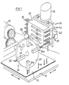
- the machine according to the invention comprises principally : - a programmable X-Y table, which in itself is known and forms no part of the present invention, on which a printed circuit plate is fixed; - an intermittently rotating distribution head fixed on top of this table, provided with a mechanism for picking up a contact pin from a supplying device and for insertion of this pin into a printed circuit plate fixed on the X-Y table; - a supplying device which is laterally movable with respect to this distribution head for the automatic and selective supply of at least two different kinds of pins and provided with a mechanism for separate cutting from the supply line of a pin and for directing and aligning of this pin; - an anvil mechanism attached to the bottom of the X-Y table to stop the pin at the bottom of the printed circuit plate.
- these contact pins have the same dimensions, but they are provided with a different coating, viz. completely gold-coated, only partially gold-coated or also without gold coating, or only covered with a lead-tin coating.
- the machine comprises in accordance with the invention in principle the following parts : -an X-Y table 10 with printed circuit plate 12 attached to it; - a distribution head 20 consisting of an intermittently rotatable wheel 102 driven by a motor 22 and equipped with a number of radial arms and with movable gripping- and insertion devices 26; - a magazine holder 30 mounted sideways of this distribution head 20, with a magazine 34 which is vertically movable by a motor 32 and equipped for example with four superposed feeding- and guiding slots 36 for various kinds of pins 14, a feeding mechanism 38 and a cutting mechanism 39 driven by a motor 40.
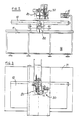
- the distribution head 20 with four arms 24 is rotated by motor 22 step by step over 90° in the direction of arrow A.
- each stop one of the arms 24a which is in horizontal position opposite the magazine, can catch a fed and cut-off pin whereas at the same time one of the arms 24b which is orientated vertically towards the printed circuit plate inserts a pin picked up in the previous position into the hole in plate 12 intended for that purpose.
- the movable magazine 34 takes care that each time the appropriate pin 14 is selected by adjusting the height alignment between the corresponding guiding slot 36 and the horizontal arm 24a.
- the X-Y table 10 is mounted on an underframe 11 equipped with a control panel 15 of a self-contained machine.
- the distribution head 20 and the magazine holder 30 with their accessory control mechanisms are located.
- the anvil mechanism 80 is fixed.
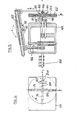
- the distribution head 20 and its control mechanism are represented in figures 4, 5, 7 and 8.
- the housing 101 of this assembly contains a mechanism which is immersed in an oil bath and driven by an electric motor (DC motor) by way of a drive shaft 109.
- DC motor electric motor
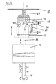
- This arm 26b is at that moment underneath as indicated in fig. 1 and drives the pin which it holds into the plate.
- This slide also drives during its vertical movement a cross-slide 106.
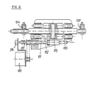
- the way in which the vertical movement of slide 105 moves at the same time the radial arm 24b and the cross-slide 106 is elucidated by fig. 7.
- slide 105 is halfway its vertical downward movement.
- slide 105 On the backside of slide 105 is an oblique groove 116 and the cross-slide 106 is equipped with a tooth 117 which can move in this oblique groove 116.
- cross-slide 106 can only move horizontally with respect to the distribution head 20 it will consequently be clear that because of a movement of slide 105 from the top downward and because of the concerted action of the oblique groove 116 and tooth 117 the cross-slide moves from left to right.
- cross-slide 106 During its movement from left to right cross-slide 106 takes along radial arm 24a by means of a projection 121, fixed on each radial arm 24 and which in this case forms part of arm 24a moving in concert with a groove segment 119 of cross-slide 106.
- Groove segments 119 and 120 mentioned above form part of a circular groove 118 which is provided in both slides 105 and 106.
- these groove segments 119 and 120 are in line with the circular groove 118 and wheel 102 of distribution head 20 together with the four radial arms 24 can rotate freely, as the respective projections 121 of arms 24 can then move freely in the circular groove 118.
- Each arm 24 is equipped with a fixed finger 122 and a hinged finger 123 as shown in figure 8.
- Hinged finger 123 can move around a spindle 124, which forms part of the arm, and is pressed under normal conditions against the fixed finger 122 by means of a spring 125.
- the end of hinged finger 123 pointing towards the center is provided with a pawl 108 which protrudes towards the back sticking out of wheel 102 which can move in concert with a cam 107 located behind wheel 102 and which can move towards the wheel or away from the wheel.
- This cam 107 takes care of opening and closing the hinged finger 123 of arm 24a during the gripping and holding of a pin 14 from the magazine 34.
- pawl 108 follows the curve of cam 107 in such a way that at a given moment hinged finger 103 is opened against the working of spring 125. In this position which in fact is the extreme right position, a pin 14 is caught from magazine 34. At that moment hinged finger 123 is released and clamps pin 14 a against fixed finger 122 by means of spring 125.
- Cam 107 which was positioned during the outward movement of arm 24a near wheel 102, is moved away at that moment from wheel 102 in such a way that pawl 108 no longer is in touch with the curve of the cam and consequently hinged finger 123 remains closed (movement according to arrow C in fig. 5).
- a pin 14 is thus also inserted into printed circuit plate 12 due to the vertical movement of slide 105 (movement according to arrow B in figure 5).
- This movement is caused by the oscillating movement of lever 103 around spindle 113.
- lever 103 The front end of lever 103 is attached by a hinged connection to slide 105 and in the rear the lever is attached by a hinged connection to actuating rod 104.
- spindle 113 around which lever 103 oscillates is mounted in a slide 112 which can move with respect to the lever in longitudinal direction.
- This slide 112 is actuated by a separate motor 110, which drives a revolving ball rod 111 the screw-thread of which moves in concert with slide 112.
- a construction of the feeding magazine 30 is shown in cross section in figure 9.
- Magazine 30 comprises a vertically movable selector 126 provided with four guiding slots 36 along which strips with cut-out pins of various kinds can be fed.
- each of the guiding slots 36 is regulated by a slide 127 which includes the selector 126 and which is actuated by a revolving ball rod 128 connected to the motor 32 (figure 1), preferably a DC motor with encoder.
- This motor ensures that guiding slot 36 is brought at the same level as cutting mechanism 39 with the appropriate strip of pins.
- This cutting mechanism 39 must ensure that the pin supplied is cut from the carrying strip and that this cut-off pin remains clamped till it is taken over by the gripping fingers 122, 123 of arm 24a.
- the cutting mechanism 39 is driven by a motor 40, preferably also a DC-motor with decoder, which drives a cam-operated mechanism 130 in an oil bath by way of a coupling 41 and a drive shaft 42.
- the feeding and clamping of the strip by the rods 131 and 132 is done by known means normally used for the feeding of one single strip with pre-cut pins and which are not discussed in this description.
- the bottom side of the feeding slot 36 must be at the same level as the upper side of the fixed gripping finger 122 of arm 24a.
- Rod 133 is connected at the bottom by means of a coupling connector 139 with a knife 138 which is located between clamp 140 and selector 126.
- This clamp 140 is connected in 140 to rod 134 and is subject to the pressure of a spring 142.
- Rod 135 is connected by means of a connecting piece 137 to a slide 143 at the upper side of which anvil 144 is fixed.
- an exhaust pipe 145 is mounted for the removal of the cut-off carrying strip and burrs, if any.
- an appropriate thread and nut connection is provided in order to enable the adjustment of the separate movements.
- An anvil mechanism 80 under X-Y table 10 is shown in figure 10.
- This mechanism is driven by a rotating shaft 55 which is driven by a DC-motor (not shown in the figure) and which extends towards the inside of a housing 54.
- Inside housing 54 is a known type of cam mechanism, which converts the rotating movement of the incoming shaft 55 into an up-and-downward movement of an outgoing shaft 53.
- This outgoing shaft 53 is connected to the frame 60 of anvil 47 by means of regulating screws.
- anvil 47 During the insertion of a pin 14 anvil 47 must be located against the bottom of printed circuit plate 12 in order to prevent the deflection of same.
- anvil 47 During the movement of X-Y table 10 anvil 47 must withdraw, however, till under the pin section in order to prevent any contact with the pins already inserted.
- Anvil 47 is further equipped with a mechanism to control and confirm the presence of the pin during the insertion.
- a small pin 48 is moved downward during the insertion of a pin 14 into plate 12. This small pin then pushes against a lever 50 which pivots around its hinge point 61.
- lever 50 moves past a detector (h) which is mounted on a support 49.
- the detector then confirms the presence of a pin in this place in plate 12.
- the height of the anvil can be adjusted. It must be adjusted in such a way that it touches in its upper position the bottom of printed circuit plate 12.
- control panel 15 (figure 2) by means of tell-tale lamps or socalled LEDs.
- LEDs are also fitted to check the position of selector 126 for magazine 30, viz, "upper limit”, “zero position” and “lower limit”.
- a panel 15 with LED-indicators is installed on the machine as shown in fig. 2.
- the first three conditions are displayed thereon.
- the fourth condition is indicated on the control panel. If one of these conditions is not fulfilled, this must be readjusted manually.
- this key table 10 moves towards its parking position and selector 12 to the first programmed position.
- the distribution head mechanism terminates its run and brings the pin which it picked up above plate 12.
- the movement of table 10 occurs when the detector (b) activates the switch for "distribution head in free-running position". This happens at the moment when arm 24b during the upward movement is outside the pin area.
- detector (d) activates the switch for "distribution head arm down”.
- the detector (h) does not activate the switching for "continuity test” and the display indicates "continuity fault”.
- a signal lamp on the control panel lights up and the machine stops.
- a "continuity fault” a visual control by the operator is necessary in order to find out what happened: - It is possible that the pin has been bent and in most cases it will then be in arm 24 on the left side. This pin must then be removed. - It is possible that a pin has not been picked up and is still in the cutting mechanism 39, from where it must also be removed. When everything is in good order again, the "restart” key must be pushed and the machine will continue to operate normally.
Landscapes
- Engineering & Computer Science (AREA)
- Manufacturing & Machinery (AREA)
- Microelectronics & Electronic Packaging (AREA)
- Supply And Installment Of Electrical Components (AREA)
- Push-Button Switches (AREA)
- Perforating, Stamping-Out Or Severing By Means Other Than Cutting (AREA)
Applications Claiming Priority (2)
| Application Number | Priority Date | Filing Date | Title |
|---|---|---|---|
| BE0/215930A BE903742A (nl) | 1985-11-29 | 1985-11-29 | Machine en werkwijze voor het selektief insteken van electrische kontaktpennen in een plaat met gedrukte schakelingen. |
| BE215930 | 1985-11-29 |
Publications (2)
| Publication Number | Publication Date |
|---|---|
| EP0230870A1 true EP0230870A1 (de) | 1987-08-05 |
| EP0230870B1 EP0230870B1 (de) | 1991-01-02 |
Family
ID=3843945
Family Applications (1)
| Application Number | Title | Priority Date | Filing Date |
|---|---|---|---|
| EP86870175A Expired - Lifetime EP0230870B1 (de) | 1985-11-29 | 1986-11-27 | Maschine und Bearbeitungsverfahren für eine auswählende Einsetzung von elektrischen Kontaktstiften auf einer gedruckten Schaltungsplatte |
Country Status (9)
| Country | Link |
|---|---|
| US (1) | US4763400A (de) |
| EP (1) | EP0230870B1 (de) |
| JP (1) | JPH07105630B2 (de) |
| CN (1) | CN1008876B (de) |
| BE (1) | BE903742A (de) |
| CA (1) | CA1259424A (de) |
| DE (1) | DE3676478D1 (de) |
| ES (1) | ES2019300B3 (de) |
| NO (1) | NO168740C (de) |
Cited By (5)
| Publication number | Priority date | Publication date | Assignee | Title |
|---|---|---|---|---|
| GB2250458A (en) * | 1990-10-30 | 1992-06-10 | Komatsu Giken Kk | Electronic component assembly apparatus |
| GB2261180A (en) * | 1991-11-08 | 1993-05-12 | Murata Manufacturing Co | Press machine for chip components |
| ES2308886A1 (es) * | 2006-04-11 | 2008-12-01 | Construcciones Mecanicas Jose Lazpiur S.A. | Un cabezal de corte, alimentacion e insercion automaticos de lenguetas en placas de circuito impreso. |
| DE102007027877B4 (de) * | 2007-06-18 | 2009-10-29 | Grohmann Engineering Gmbh | Kalibriervorrichtung für einen Setzkopf für Kontaktelemente |
| WO2016023748A1 (en) * | 2014-08-12 | 2016-02-18 | Tyco Electronics Amp Gmbh | A tool and a device with same, as well as a method for pressing in printed circuit board contacts |
Families Citing this family (27)
| Publication number | Priority date | Publication date | Assignee | Title |
|---|---|---|---|---|
| US4910864A (en) * | 1986-05-16 | 1990-03-27 | Western Digital Corporation | Pick-up head for component handling machine |
| US4905368A (en) * | 1987-12-30 | 1990-03-06 | Brown Maurice H | Terminal forming and inserting apparatus |
| JPH0810797B2 (ja) * | 1989-06-05 | 1996-01-31 | 富士通株式会社 | コネクタピン圧入装置及びバックアップ機構 |
| US5074030A (en) * | 1990-10-31 | 1991-12-24 | Molex Incorporated | Press and modular press block for electrical connector application tooling |
| JPH07212005A (ja) * | 1994-01-21 | 1995-08-11 | Pioneer Electron Corp | Pcb作成装置 |
| EP0755102A3 (de) * | 1995-07-21 | 1997-08-13 | Gregory W Holcomb | Kontinuierliche Anspeisung von Pin-Konnektorblockstreifen |
| JP2970489B2 (ja) * | 1995-09-11 | 1999-11-02 | 住友電装株式会社 | アダプター供給装置 |
| BE1009814A5 (nl) | 1995-11-06 | 1997-08-05 | Framatome Connectors Belgium | Werkwijze en inrichting voor het aanbrengen van elektronische onderdelen in een plaat met gedrukte schakelingen. |
| US5701662A (en) * | 1995-11-06 | 1997-12-30 | Matsushita Electric Industrial Co., Ltd. | Axial type electronic component inserting apparatus |
| CN1057987C (zh) * | 1996-08-20 | 2000-11-01 | 中国石油化工总公司 | 一种乳化炸药 |
| BE1010707A3 (nl) * | 1996-10-23 | 1998-12-01 | Framatome Connectors Belgium | Werkwijze voor het indrukken van een elektrische contactpen met een elastische bevestigingszone in een gat van een bedrukte schakelplaat. |
| GB2333904B (en) | 1998-01-29 | 2002-07-17 | John Michael Lowe | Component placement apparatus |
| FR2788634B1 (fr) * | 1999-01-14 | 2001-02-23 | S M Contact | Systeme pour implanter des broches dans un dispositif tel que, par exemple, un connecteur |
| DE102007054454B4 (de) * | 2007-11-13 | 2010-08-26 | Tyco Electronics Amp Gmbh | Vorrichtung und Verfahren zum Bestücken von Leiterplatten mit Kontaktstiften |
| DE102009046589B3 (de) * | 2009-11-10 | 2011-07-07 | Tyco Electronics AMP GmbH, 64625 | Verfahren und Vorrichtung zum Bestimmen einer Abstandsposition eines Kontaktendes zu einer Leiterplatte |
| CN103118525A (zh) * | 2013-01-22 | 2013-05-22 | 宗智辉 | 一种电子元件散料高速自动插件机 |
| SG10201500850SA (en) * | 2015-02-04 | 2016-09-29 | Ziontech Pte Ltd | Assembly apparatus |
| CN107396537B (zh) * | 2017-07-19 | 2019-05-03 | 合肥皖创电子科技有限公司 | 一种用于电路板切边打孔一体设备 |
| CN108832457A (zh) * | 2018-08-01 | 2018-11-16 | 苏州宜广科技有限公司 | 连接器自动组装生产设备 |
| CN109049092B (zh) * | 2018-09-07 | 2024-08-30 | 先进光电器材(深圳)有限公司 | 自动割膜机构 |
| CN109986331A (zh) * | 2019-05-07 | 2019-07-09 | 瑞安市东风汽车标准件有限公司 | 一种汽车用膨胀螺栓的高效组装设备 |
| CN111250948A (zh) * | 2020-03-13 | 2020-06-09 | 余姚市耐德自动化科技有限公司 | 一种sd整体阀芯接头自动组装机 |
| CN112117223B (zh) * | 2020-11-18 | 2021-02-26 | 常州科瑞尔科技有限公司 | Igbt模块的自动插针机 |
| CN113218176A (zh) * | 2021-04-08 | 2021-08-06 | 涌明科技(上海)有限公司 | 一种多功能硅片烘烤用储存装置 |
| CN114536006B (zh) * | 2022-04-26 | 2022-07-12 | 南通亨德利电动工具有限公司 | 一种激光水平仪的组装设备 |
| KR102510677B1 (ko) * | 2022-12-19 | 2023-03-16 | 주식회사 성우플라텍 | 커넥터 핀 공급장치 |
| KR102684304B1 (ko) * | 2023-11-03 | 2024-07-11 | (주)비올 | 자동 삽입 장치 및 방법 |
Citations (4)
| Publication number | Priority date | Publication date | Assignee | Title |
|---|---|---|---|---|
| GB2020583A (en) * | 1978-05-10 | 1979-11-21 | Itt | Assembly apparatus for electrical connectors |
| US4265508A (en) * | 1978-11-30 | 1981-05-05 | Western Electric Company, Inc. | Intermediate-web held terminal pins |
| US4287668A (en) * | 1977-08-27 | 1981-09-08 | Fuji Mfg. Co. Ltd. | Method of inserting electronic components to a printed circuit board |
| DE3424323A1 (de) * | 1983-07-01 | 1985-01-10 | Sanyo Electric Co., Ltd., Moriguchi, Osaka | Automatische montagevorrichtung |
Family Cites Families (4)
| Publication number | Priority date | Publication date | Assignee | Title |
|---|---|---|---|---|
| JPS5961200A (ja) * | 1982-09-30 | 1984-04-07 | 株式会社東芝 | Dip型ic插入装置 |
| JPS59102538A (ja) * | 1982-11-30 | 1984-06-13 | Fujitsu Ltd | コネクタピンインサ−タ |
| JPS59205240A (ja) * | 1983-05-06 | 1984-11-20 | Toshiba Corp | 自動組立装置 |
| US4612700A (en) * | 1985-04-26 | 1986-09-23 | Amp Incorporated | Component insertion apparatus |
-
1985
- 1985-11-29 BE BE0/215930A patent/BE903742A/nl not_active IP Right Cessation
-
1986
- 1986-11-20 US US06/932,937 patent/US4763400A/en not_active Expired - Lifetime
- 1986-11-25 CA CA000523786A patent/CA1259424A/en not_active Expired
- 1986-11-27 NO NO864778A patent/NO168740C/no unknown
- 1986-11-27 ES ES86870175T patent/ES2019300B3/es not_active Expired - Lifetime
- 1986-11-27 DE DE8686870175T patent/DE3676478D1/de not_active Expired - Lifetime
- 1986-11-27 EP EP86870175A patent/EP0230870B1/de not_active Expired - Lifetime
- 1986-11-28 JP JP61284072A patent/JPH07105630B2/ja not_active Expired - Fee Related
- 1986-11-29 CN CN86108129A patent/CN1008876B/zh not_active Expired
Patent Citations (4)
| Publication number | Priority date | Publication date | Assignee | Title |
|---|---|---|---|---|
| US4287668A (en) * | 1977-08-27 | 1981-09-08 | Fuji Mfg. Co. Ltd. | Method of inserting electronic components to a printed circuit board |
| GB2020583A (en) * | 1978-05-10 | 1979-11-21 | Itt | Assembly apparatus for electrical connectors |
| US4265508A (en) * | 1978-11-30 | 1981-05-05 | Western Electric Company, Inc. | Intermediate-web held terminal pins |
| DE3424323A1 (de) * | 1983-07-01 | 1985-01-10 | Sanyo Electric Co., Ltd., Moriguchi, Osaka | Automatische montagevorrichtung |
Cited By (9)
| Publication number | Priority date | Publication date | Assignee | Title |
|---|---|---|---|---|
| GB2250458A (en) * | 1990-10-30 | 1992-06-10 | Komatsu Giken Kk | Electronic component assembly apparatus |
| US5210933A (en) * | 1990-10-30 | 1993-05-18 | Komatsu Giken Co., Ltd. | Circuit assembly robot |
| GB2261180A (en) * | 1991-11-08 | 1993-05-12 | Murata Manufacturing Co | Press machine for chip components |
| US5249906A (en) * | 1991-11-08 | 1993-10-05 | Murata Manufacturing Co., Ltd. | Press machine for chip type electronic components |
| GB2261180B (en) * | 1991-11-08 | 1994-09-14 | Murata Manufacturing Co | Press machine for chip type electronic components |
| ES2308886A1 (es) * | 2006-04-11 | 2008-12-01 | Construcciones Mecanicas Jose Lazpiur S.A. | Un cabezal de corte, alimentacion e insercion automaticos de lenguetas en placas de circuito impreso. |
| ES2308886B1 (es) * | 2006-04-11 | 2009-11-05 | Construcciones Mecanicas Jose Lazpiur S.A. | Un cabezal de corte, alimentacion e insercion automaticos de lenguetas en placas de circuito impreso. |
| DE102007027877B4 (de) * | 2007-06-18 | 2009-10-29 | Grohmann Engineering Gmbh | Kalibriervorrichtung für einen Setzkopf für Kontaktelemente |
| WO2016023748A1 (en) * | 2014-08-12 | 2016-02-18 | Tyco Electronics Amp Gmbh | A tool and a device with same, as well as a method for pressing in printed circuit board contacts |
Also Published As
| Publication number | Publication date |
|---|---|
| ES2019300B3 (es) | 1991-06-16 |
| EP0230870B1 (de) | 1991-01-02 |
| NO168740B (no) | 1991-12-16 |
| JPH07105630B2 (ja) | 1995-11-13 |
| DE3676478D1 (de) | 1991-02-07 |
| US4763400A (en) | 1988-08-16 |
| BE903742A (nl) | 1986-05-29 |
| CN86108129A (zh) | 1987-10-07 |
| NO168740C (no) | 1992-03-25 |
| JPS62152200A (ja) | 1987-07-07 |
| CA1259424A (en) | 1989-09-12 |
| NO864778D0 (no) | 1986-11-27 |
| CN1008876B (zh) | 1990-07-18 |
Similar Documents
| Publication | Publication Date | Title |
|---|---|---|
| EP0230870B1 (de) | Maschine und Bearbeitungsverfahren für eine auswählende Einsetzung von elektrischen Kontaktstiften auf einer gedruckten Schaltungsplatte | |
| CA1056512A (en) | Machine for affixing circuit elements to printed circuit boards | |
| US3727284A (en) | Apparatus for selecting and inserting dual in-line components | |
| US3941294A (en) | Wire bonding apparatus with improved Z-axis motion control | |
| CN113441930B (zh) | 一种具有自动上料功能的机电产品组装系统 | |
| US5706570A (en) | Terminal crimping device | |
| US4313251A (en) | System for applying electronic components to a circuit board | |
| CA1090546A (en) | Machines for board mounting and socket mounting components | |
| US4461061A (en) | Apparatus for connecting wire to insulation displacement-type contacts | |
| US3796363A (en) | Multiple component insertion apparatus | |
| US4621406A (en) | Electronic component insertion apparatus | |
| CN116203037A (zh) | 一种pcb板加工用检测装置 | |
| GB842623A (en) | Improvements relating to apparatus for automatically assembling electrical components on a circuit matrix | |
| US3591911A (en) | Machine and method for mounting electrical components on a printed circuit board | |
| JPS6243359B2 (de) | ||
| JPH0252500A (ja) | ラジアルテーピング電子部品の供給装置 | |
| CN100496846C (zh) | 陶瓷谐振器焊装机 | |
| EP0117097B1 (de) | Vorrichtung zum Aufrichten von Haken an halbfertigen Federn | |
| US3429039A (en) | Apparatus and method for inserting groups of lead wires in a circuit board | |
| EP0118629A2 (de) | Apparat zum Einsetzen eines elektronischen Bauelementes | |
| US5008999A (en) | Method of assembling components to electrical terminals | |
| CN121192480B (zh) | 一种附带智能定位功能的家用电器线束生产装置 | |
| JPS6181700A (ja) | 電子部品自動挿入機 | |
| JP2697034B2 (ja) | 電子部品移載装置 | |
| JPS61105900A (ja) | 電子部品自動插入機 |
Legal Events
| Date | Code | Title | Description |
|---|---|---|---|
| PUAI | Public reference made under article 153(3) epc to a published international application that has entered the european phase |
Free format text: ORIGINAL CODE: 0009012 |
|
| AK | Designated contracting states |
Kind code of ref document: A1 Designated state(s): DE ES FR GB IT NL |
|
| 17P | Request for examination filed |
Effective date: 19870929 |
|
| 17Q | First examination report despatched |
Effective date: 19890802 |
|
| GRAA | (expected) grant |
Free format text: ORIGINAL CODE: 0009210 |
|
| AK | Designated contracting states |
Kind code of ref document: B1 Designated state(s): DE ES FR GB IT NL |
|
| REF | Corresponds to: |
Ref document number: 3676478 Country of ref document: DE Date of ref document: 19910207 |
|
| ITF | It: translation for a ep patent filed | ||
| ET | Fr: translation filed | ||
| PLBE | No opposition filed within time limit |
Free format text: ORIGINAL CODE: 0009261 |
|
| STAA | Information on the status of an ep patent application or granted ep patent |
Free format text: STATUS: NO OPPOSITION FILED WITHIN TIME LIMIT |
|
| 26N | No opposition filed | ||
| PGFP | Annual fee paid to national office [announced via postgrant information from national office to epo] |
Ref country code: GB Payment date: 19921030 Year of fee payment: 7 |
|
| PG25 | Lapsed in a contracting state [announced via postgrant information from national office to epo] |
Ref country code: GB Effective date: 19931127 |
|
| GBPC | Gb: european patent ceased through non-payment of renewal fee |
Effective date: 19931127 |
|
| PGFP | Annual fee paid to national office [announced via postgrant information from national office to epo] |
Ref country code: ES Payment date: 20041008 Year of fee payment: 19 |
|
| PGFP | Annual fee paid to national office [announced via postgrant information from national office to epo] |
Ref country code: NL Payment date: 20041129 Year of fee payment: 19 |
|
| PGFP | Annual fee paid to national office [announced via postgrant information from national office to epo] |
Ref country code: FR Payment date: 20051104 Year of fee payment: 20 |
|
| PG25 | Lapsed in a contracting state [announced via postgrant information from national office to epo] |
Ref country code: IT Free format text: LAPSE BECAUSE OF NON-PAYMENT OF DUE FEES;WARNING: LAPSES OF ITALIAN PATENTS WITH EFFECTIVE DATE BEFORE 2007 MAY HAVE OCCURRED AT ANY TIME BEFORE 2007. THE CORRECT EFFECTIVE DATE MAY BE DIFFERENT FROM THE ONE RECORDED. Effective date: 20051127 |
|
| PG25 | Lapsed in a contracting state [announced via postgrant information from national office to epo] |
Ref country code: ES Free format text: LAPSE BECAUSE OF NON-PAYMENT OF DUE FEES Effective date: 20051128 |
|
| PGFP | Annual fee paid to national office [announced via postgrant information from national office to epo] |
Ref country code: DE Payment date: 20051130 Year of fee payment: 20 |
|
| PG25 | Lapsed in a contracting state [announced via postgrant information from national office to epo] |
Ref country code: NL Free format text: LAPSE BECAUSE OF NON-PAYMENT OF DUE FEES Effective date: 20060601 |
|
| NLV4 | Nl: lapsed or anulled due to non-payment of the annual fee |
Effective date: 20060601 |
|
| REG | Reference to a national code |
Ref country code: ES Ref legal event code: FD2A Effective date: 20051128 |