EP0231907A2 - Übertragungssteuerungsvorrichtung für Duplex-Ringübertragungssystem - Google Patents
Übertragungssteuerungsvorrichtung für Duplex-Ringübertragungssystem Download PDFInfo
- Publication number
- EP0231907A2 EP0231907A2 EP87101315A EP87101315A EP0231907A2 EP 0231907 A2 EP0231907 A2 EP 0231907A2 EP 87101315 A EP87101315 A EP 87101315A EP 87101315 A EP87101315 A EP 87101315A EP 0231907 A2 EP0231907 A2 EP 0231907A2
- Authority
- EP
- European Patent Office
- Prior art keywords
- transmission
- circuit
- stations
- trouble
- station
- Prior art date
- Legal status (The legal status is an assumption and is not a legal conclusion. Google has not performed a legal analysis and makes no representation as to the accuracy of the status listed.)
- Withdrawn
Links
Images



Classifications
-
- H—ELECTRICITY
- H04—ELECTRIC COMMUNICATION TECHNIQUE
- H04L—TRANSMISSION OF DIGITAL INFORMATION, e.g. TELEGRAPHIC COMMUNICATION
- H04L12/00—Data switching networks
- H04L12/28—Data switching networks characterised by path configuration, e.g. LAN [Local Area Networks] or WAN [Wide Area Networks]
- H04L12/42—Loop networks
- H04L12/437—Ring fault isolation or reconfiguration
Definitions
- This invention relates to a transmission control apparatus for a duplex loop type transmission system, and more particularly to a transmission control apparatus which is capable of immediately cleaning trouble occurring on transmission lines.
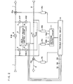
- reference numeral 3 designates a data transmit-receive control circuit
- 5 through 10 designate switching circuits for switching the transmission lines
- 11 designates a switching control circuit for the switching circuits 5 through 10
- 12a and 12b designate detection circuits of a network switching signal for a local station
- 13a and 13b designate delivery circuits for a network switching command to perform the network switching control for other stations
- 14 designates a trouble control circuit which carries out trouble control by a trouble processing demand signal from the data transmit-receive control circuit 3.
- the data transmit-receive control circuit 3 at the transmission station 3a detects an occurrence of trouble on the transmission lines due to non-response to the data transmission or a frame error detection by the cyclic check, and then output a trouble clearing demand 51 with respect to the trouble control circuit 14 at the station 3a, so that the trouble control circuit 14 carries out the loopback control and continuity test of the respective transmission stations 3b through 3d by use of one transmission line 1.
- the network switching command delivery circuit 13a delivers a loopback test command for the transmission line 1 to the transmission station 3b via a switching circuit 15a on the transmission line 1. Then, the transmission station 3b receives the command signal by the detection circuit 12a of the network switching signal for the station 3b and closes the switching circuits 5 and 8 through the switching control circuit 11, thereby making the transmission lines in the system switching condition for the loopback of the transmission line 1, in other words, the condition that the signal sent through the transmission line 1 is returned to the transmitting side from the transmission line 2 through the data transmit-receive control circuit 3.
- the trouble control circuit 14 at the transmission station 3a delivers a signal to the switching control circuit 11 to close the switching circuits 6 and 7 so as to make the system switching condition for the loopback of the transmission line 2, and a test data delivery signal 52 is delivered to the data transmit-receive control circuit 3 to thereby allow the circuit 3 to transmit the test data to the transmission station 3b.
- test data returns to the station 3a via the switching circuit 5 - data transmit-receive control circuit 3 - switching circuit 8 - switching circuit 15b interposed in the transmission line 2 - at the transmission station 3b.
- the test data having thus returned to the transmission station 3a is received by the data transmit-receive control circuit 3 through the switching circuit 6.
- the data transmit-receive control circuit 3 feeds to the trouble control circuit 14 a reception confirming signal 53 indicating the reception of the test data.
- the trouble control circuit 1 4 receives the signal 53 to decide that the transmission lines between the transmission stations 3a and 3b are normal so as to deliver a straight command for the transmission line 1 to the transmission station 3b from the network switching command delivery circuit 13a through the switching circuit 15a.
- the command is received by the detection circuit 12a for the network switching signal for the station 3b and the switching circuits 5 and 7 are closed through the switching control circuit 11, thereby making the transmission line 1 switch into straight condition, in other words, the condition that the signal having transmitted through the transmission line 1 is returned thereto through the data transmit-receive control circuit 3.
- the loopback control and continuity test for the transmission station 3b is completed and similarly the transmission station 3a carries out control for the transmission stations 3c and 3d.
- the test data reception confirming signal 53 is not given to the trouble control circuit'14 at the transmission station 3a, whereby abnormality between the transmission stations 3c and 3d is checked by the trouble control circuit 14.
- the transmission station 3c is reswitched to the transmission line 1 system loopback, thereby completing the test and the network formation to the transmission line 1.
- the loopback control and continuity test of the line 2 for the transmission stations 3d through 3b are carried out from the transmission station 3a with respect to the transmission line 2 in the same way as the line 1.
- the transmission station 3d one station before that 3c,where the abnormality has been detected, carries out the loopback of the transmission line 2, so that the portions at the transmission lines 1 and 2 between the transmission stations 3c and 3d are separated from the loop as shown in Fig. 3, thereby forming the closed loop at the respective transmission stations 3c and 3d, thus completing the trouble control.
- reference numerals 35 through 40 designate control signals given from the switching control circuit 11 with respect to the switching circuits 5 through 10,respectively.
- the conventional transmission control apparatus for duplex loop type transmission system constituted as foregoing, is controlled sequentially, thereby occurring the problem in that it takes much time to clear the trouble.
- the present invention has been designed in order to solve the above-mentioned problem.
- a first-nbject of the invention is to provide a transmission control apparatus which allows the transmission station having the control rightto deliver check signals simultaneously to other stations through the transmission line on which trouble occurs and response signals with respect to the check signals are adapted to be delivered from the other stations to the adjacent station at the upstream side of the signal flow, so that when no response signal is obtained, the adjacent station closes the loop of transmission line, thereby enabling the trouble clearing to be quickly completed.
- a second object of the invention is to provide a transmission control apparatus in which the transmission station having the control right gives a command to other stations, so that the other stations are put simultaneously in the straight condition as to the transmission lines,in the reverse direction to those where the trouble is detected to thereby detect whether the trouble occurs or not, and thereafter when trouble is not detected, transmission is carried out though the transmission line and when trouble is detected, the check signal as above-mentioned is transmitted and the response signal is received at each transmission station to detect the abnormality, thereby enabling the transmission to be restarted immediately after the detection, thus expecting reduction of the time for clearing the trouble.
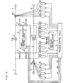
- Fig. 4 is a block diagram of the transmission control apparatus of the invention housed in each transmission station 3a, 3b, 3c or 3d at a duplex loop type transmission system in Fig. 1, in which the same components as those in Fig. 2 are designated by the same reference numerals.
- a switching circuit 5 is interposed between the node at the upstream side of the signal flow with respect to the switching circuit 9 at the transmission line 1 and a data transmit-receive control circuit 3, a switching circuit 7 between the data transmit-receive circuit 3 and the node at the line 1 between the switching circuits 9 and 15a, a switching circuit 6 between the node at the upstream side of the signal flow with respect to the switching circuit 10 at the transmission line 2 and the data transmit-receive control circuit 3, and a switching circuit 8 between the data transmit-receive control circuit 3 and the node at the line 2 between the switching circuits 10 and 15b, these switching circuits 5 through 10 being given switching control signals 35 through 40 from the switching control circuit 11.
- the data transmit-receive control circuit 3 serves as the center for the transmit-receive control for each transmission station, which delivers to the trouble control circuit 14 a trouble clearing demand 51 when a trouble is detected, the trouble control circuit 14 receiving the demand 51 to perform the control to be described hereinafter.
- the trouble control circuit 14 when its station has the control right, delivers the simultaneous system switching commands to the transmission lines 1 and 2 through delivery circuits 16a and 16b and switching circuits 15a and 15b. For the station having no control right, the command is received by the switching control circuit 11 thereof from the transmission lines 1 and 2 through receiver circuits 19a and 19b.
- the trouble control circuit 14 when the station thereof has the control right, delivers simultaneous check signals for the adjacent stations to the transmission lines 1 and 2 through delivery circuits 17a and 17b and the switching circuits 15a and 15b.
- the check signal is received by the trouble control circuit 14 form the transmission lines 1 and 2 thought receiver circuits 20a and 20b.
- the trouble control circuit 14 at the station receiving the check signal outputs the response signal to the adjacent station at the upstream side of the signal flow, the response signal being sent out to the transmission lines 1 and 2 through the delivery circuits 18a and 18b and switching circuits 15a and 15b.
- the response signal thus beingdelivered is introduced into the trouble control circuit 14 from the transmission circuits 1 and 2 through receiver circuits 21aand. 21b.
- the data transmit-receive control circuit 3 at the station 3a detects a trouble by non-response to the data transmission, detection of frame error due to the cyclic check and the like. Now, assuming that the trouble detection is carried out regarding the transmission line 1, the data transmit-receive control circuit 3 gives to the trouble control circuit 14 the trouble clearing demand 51 to command inspection of the transmission line 2.
- the trouble control circuit 14 at the transmission station 3a receives the demand 51 and delivers to the transmission line 2 through the delivery circuit 16b and switching circuit 15b the simultaneous system switching command to make the line 2 straight. Other stations receive the command by the switching control circuit 11 through the receiver circuit 19b and close the switching circuits 6 and 8, thereby putting the transmission line 2 in the straight condition.
- the trouble control circuit 14 at the transmission station 3a gives a test data sending signal 52 to the data transmit-receive control circuit 3 to thereby deliver therefrom the test data to carry out continuity test.
- the data transmit-receive control circuit 3 is to deliver a reception confirming signal 53 to the trouble control circuit 14, thereafter transmission is carried out through only the transmission line 2. Since the transmission line 2 is also disconnected in this example, the data transmit-receive control circuit 3 gives the trouble clearing demand 51 again to the trouble control circuit 14.
- the trouble control circuit 14 receives the demand 51 to firstly deliver the simultaneous adjacent station check signals to the transmission line 1 through the delivery circuit 17a and switching circuit 15a, at which time the transmission line 1 is kept straight, whereby a trouble control circuit 14 at the transmission station connecting with the normal line receives the check signal through a receiver circuit 20a and delivers a response signal to the adjacent station at the upstream side of the signal flow.
- trouble control circuits 14 at the transmission stations 3b and 3c each delivers the response signals to the transmission line 2 through a delivery circuit 18b and a switching circuit 15b, resulting in that the respective transmission stations 3a and 3b for the transmission line 1 and adjacent to those 3b and 3c at the upstream sides of the signal flow receive the response signals through the receiver circuits 21b.
- the stations having obtained the response signals finish the control as to the transmission line 1, respectively.
- the transmission station 3d receives no check signal because of disconnection of the transmission line 1, whereby the transmission station 3c receives no response signal.
- the trouble control circuit 14 gives the predetermined signal to the switching control circuit 11 and closes the switching circuits 5 and 8, thereby putting the stations 3c and 3d in the loopback conditions, respectively.
- the transmission line 2 is subjected to control being the same as above-mentioned, whereby the transmission station 3d in this embodiment is put into the loopback condition to thereby obtain the condition shown in Fig. 3.
- the transmission station 3a having the control right cannot receive the response signal from neither transmission line 1 nor 2, the transmission lines are not put into the loopback condition, so that the detection circuits 12a and 12b for the network switching signal for the local station and network switching command delivery circuits 13a and 13b at the station 3a are used to carry out the sequential loopback control as conventional.
- the present invention simultaneously carries out the loopback control, so that the trouble clearing at high speed is realizable, whereby the communication off-time is very short.
- the trouble occurs only on the transmission line in use, it is immediately apparent that the other line is normal before application of the loopback control, so that the transmission must be carried out immediately, thereby enabling the trouble clearing to be carried out at high speed.
Landscapes
- Engineering & Computer Science (AREA)
- Computer Networks & Wireless Communication (AREA)
- Signal Processing (AREA)
- Small-Scale Networks (AREA)
- Safety Devices In Control Systems (AREA)
Applications Claiming Priority (2)
| Application Number | Priority Date | Filing Date | Title |
|---|---|---|---|
| JP61016942A JPS62176345A (ja) | 1986-01-30 | 1986-01-30 | 2重系ル−プ形伝送制御装置 |
| JP16942/86 | 1986-01-30 |
Publications (2)
| Publication Number | Publication Date |
|---|---|
| EP0231907A2 true EP0231907A2 (de) | 1987-08-12 |
| EP0231907A3 EP0231907A3 (de) | 1989-06-07 |
Family
ID=11930183
Family Applications (1)
| Application Number | Title | Priority Date | Filing Date |
|---|---|---|---|
| EP19870101315 Withdrawn EP0231907A3 (de) | 1986-01-30 | 1987-01-30 | Übertragungssteuerungsvorrichtung für Duplex-Ringübertragungssystem |
Country Status (5)
| Country | Link |
|---|---|
| US (1) | US4760488A (de) |
| EP (1) | EP0231907A3 (de) |
| JP (1) | JPS62176345A (de) |
| AU (1) | AU587523B2 (de) |
| MX (1) | MX161941A (de) |
Families Citing this family (5)
| Publication number | Priority date | Publication date | Assignee | Title |
|---|---|---|---|---|
| GB8709072D0 (en) * | 1987-04-15 | 1987-05-20 | British Telecomm | Transmission system |
| JP3085431B2 (ja) * | 1993-03-01 | 2000-09-11 | 株式会社日立製作所 | 配電線制御システムおよびその方法 |
| JPH0713878A (ja) * | 1993-06-23 | 1995-01-17 | Matsushita Electric Ind Co Ltd | 周辺装置制御装置 |
| JP2848245B2 (ja) * | 1994-06-06 | 1999-01-20 | ブラザー工業株式会社 | プリンタ設定装置 |
| TW317556B (de) * | 1995-08-07 | 1997-10-11 | Daifuku Kk |
Family Cites Families (8)
| Publication number | Priority date | Publication date | Assignee | Title |
|---|---|---|---|---|
| CH583980A5 (de) * | 1973-11-23 | 1977-01-14 | Zellweger Uster Ag | |
| AU552312B2 (en) * | 1982-02-08 | 1986-05-29 | Racal-Milgo Limited | Communication system |
| JPS5940739A (ja) * | 1982-08-30 | 1984-03-06 | Fujitsu Ltd | ル−プパツク制御方式 |
| JPS5977739A (ja) * | 1982-10-27 | 1984-05-04 | Hitachi Ltd | 二重系環状網システム |
| US4596982A (en) * | 1983-02-14 | 1986-06-24 | Prime Computer, Inc. | Reconfigurable ring communications network |
| JPH0710068B2 (ja) * | 1983-05-09 | 1995-02-01 | キヤノン株式会社 | 伝送制御装置 |
| WO1985002078A1 (en) * | 1983-10-31 | 1985-05-09 | Beale Electronic Systems Limited | Data transmission system and method |
| AU564089B2 (en) * | 1984-01-31 | 1987-07-30 | Fujitsu Limited | Automatic loop back line testing and rerouting |
-
1986
- 1986-01-30 JP JP61016942A patent/JPS62176345A/ja active Pending
- 1986-12-30 US US06/947,919 patent/US4760488A/en not_active Expired - Fee Related
-
1987
- 1987-01-29 AU AU68124/87A patent/AU587523B2/en not_active Ceased
- 1987-01-30 MX MX5094A patent/MX161941A/es unknown
- 1987-01-30 EP EP19870101315 patent/EP0231907A3/de not_active Withdrawn
Also Published As
| Publication number | Publication date |
|---|---|
| EP0231907A3 (de) | 1989-06-07 |
| JPS62176345A (ja) | 1987-08-03 |
| US4760488A (en) | 1988-07-26 |
| MX161941A (es) | 1991-03-08 |
| AU587523B2 (en) | 1989-08-17 |
| AU6812487A (en) | 1987-08-06 |
Similar Documents
| Publication | Publication Date | Title |
|---|---|---|
| US5218600A (en) | Process for networking computers and/or computer networks and networking systems | |
| CA1193690A (en) | Multipoint data communication system with collision detection | |
| EP0102222B1 (de) | Ringübertragungssystem und Verfahren zur Steuerung seines Rückschleifzustands | |
| US4446551A (en) | Data highway system with dual transmitting loop lines | |
| US4949340A (en) | Redundant repeater | |
| US4760488A (en) | Transmission control apparatus for duplex loop type transmission system | |
| CN112882978B (zh) | 一种串行数据传输装置、方法及数据处理设备 | |
| JP2737294B2 (ja) | 受信部二重化回路 | |
| US20050157710A1 (en) | Data bus system | |
| JP2682427B2 (ja) | ループ状伝送路での障害箇所検出方式 | |
| JP3284509B2 (ja) | 現用予備切替方式 | |
| JP2739532B2 (ja) | トークンリングlanシステムの再構成制御方式 | |
| JPH0817398B2 (ja) | データ伝送システムにおける異常検出方法 | |
| AU607540B2 (en) | Repeater system | |
| KR100630066B1 (ko) | 전송 시스템에서 선로감시를 통한 메시지 전달 방법 | |
| JPH10294723A (ja) | 多重通信システム | |
| JPH01227544A (ja) | 中継器 | |
| JPH0563715A (ja) | 従局障害監視方式 | |
| JPS5819057A (ja) | ル−プ式デ−タ伝送システムの構成制御装置 | |
| JPS6083456A (ja) | トランクの導通試験方式 | |
| JPS6165556A (ja) | モニタ局障害監視方式 | |
| JPS6161539A (ja) | 信号伝送方式 | |
| JPH05153147A (ja) | 光多分岐通信における監視方式 | |
| JPH0528933B2 (de) | ||
| JPH0236635A (ja) | 受信専用局の存在するトークンバスネットワークの送信制御方式 |
Legal Events
| Date | Code | Title | Description |
|---|---|---|---|
| PUAI | Public reference made under article 153(3) epc to a published international application that has entered the european phase |
Free format text: ORIGINAL CODE: 0009012 |
|
| AK | Designated contracting states |
Kind code of ref document: A2 Designated state(s): DE ES FR GB |
|
| PUAL | Search report despatched |
Free format text: ORIGINAL CODE: 0009013 |
|
| AK | Designated contracting states |
Kind code of ref document: A3 Designated state(s): DE ES FR GB |
|
| 17P | Request for examination filed |
Effective date: 19890705 |
|
| 17Q | First examination report despatched |
Effective date: 19910723 |
|
| STAA | Information on the status of an ep patent application or granted ep patent |
Free format text: STATUS: THE APPLICATION IS DEEMED TO BE WITHDRAWN |
|
| 18D | Application deemed to be withdrawn |
Effective date: 19911203 |
|
| RIN1 | Information on inventor provided before grant (corrected) |
Inventor name: KISHIMOTO, KAZUOC/O MITSUBISHI DENKI K.K. |