EP0232128A2 - Filtrationsanlage - Google Patents
Filtrationsanlage Download PDFInfo
- Publication number
- EP0232128A2 EP0232128A2 EP87300772A EP87300772A EP0232128A2 EP 0232128 A2 EP0232128 A2 EP 0232128A2 EP 87300772 A EP87300772 A EP 87300772A EP 87300772 A EP87300772 A EP 87300772A EP 0232128 A2 EP0232128 A2 EP 0232128A2
- Authority
- EP
- European Patent Office
- Prior art keywords
- screen
- nozzles
- liquid
- support member
- filtered
- Prior art date
- Legal status (The legal status is an assumption and is not a legal conclusion. Google has not performed a legal analysis and makes no representation as to the accuracy of the status listed.)
- Withdrawn
Links
- 238000001914 filtration Methods 0.000 title claims abstract description 16
- 239000007788 liquid Substances 0.000 claims abstract description 36
- 239000007787 solid Substances 0.000 claims abstract description 20
- 238000004140 cleaning Methods 0.000 claims description 9
- 230000033001 locomotion Effects 0.000 claims description 6
- 238000000034 method Methods 0.000 claims description 3
- 230000002093 peripheral effect Effects 0.000 claims description 2
- 239000007921 spray Substances 0.000 abstract description 21
- XLYOFNOQVPJJNP-UHFFFAOYSA-N water Substances O XLYOFNOQVPJJNP-UHFFFAOYSA-N 0.000 description 8
- 238000006073 displacement reaction Methods 0.000 description 2
- 230000001609 comparable effect Effects 0.000 description 1
- 239000010419 fine particle Substances 0.000 description 1
- 239000013505 freshwater Substances 0.000 description 1
- 230000005484 gravity Effects 0.000 description 1
- 238000004519 manufacturing process Methods 0.000 description 1
- 239000002245 particle Substances 0.000 description 1
- 230000003134 recirculating effect Effects 0.000 description 1
- 239000002351 wastewater Substances 0.000 description 1
Images


Classifications
-
- D—TEXTILES; PAPER
- D21—PAPER-MAKING; PRODUCTION OF CELLULOSE
- D21F—PAPER-MAKING MACHINES; METHODS OF PRODUCING PAPER THEREON
- D21F1/00—Wet end of machines for making continuous webs of paper
- D21F1/66—Pulp catching, de-watering, or recovering; Re-use of pulp-water
-
- B—PERFORMING OPERATIONS; TRANSPORTING
- B01—PHYSICAL OR CHEMICAL PROCESSES OR APPARATUS IN GENERAL
- B01D—SEPARATION
- B01D29/00—Filters with filtering elements stationary during filtration, e.g. pressure or suction filters, not covered by groups B01D24/00 - B01D27/00; Filtering elements therefor
- B01D29/01—Filters with filtering elements stationary during filtration, e.g. pressure or suction filters, not covered by groups B01D24/00 - B01D27/00; Filtering elements therefor with flat filtering elements
- B01D29/018—Filters with filtering elements stationary during filtration, e.g. pressure or suction filters, not covered by groups B01D24/00 - B01D27/00; Filtering elements therefor with flat filtering elements ring shaped
-
- B—PERFORMING OPERATIONS; TRANSPORTING
- B01—PHYSICAL OR CHEMICAL PROCESSES OR APPARATUS IN GENERAL
- B01D—SEPARATION
- B01D29/00—Filters with filtering elements stationary during filtration, e.g. pressure or suction filters, not covered by groups B01D24/00 - B01D27/00; Filtering elements therefor
- B01D29/62—Regenerating the filter material in the filter
- B01D29/64—Regenerating the filter material in the filter by scrapers, brushes, nozzles, or the like, acting on the cake side of the filtering element
- B01D29/6438—Regenerating the filter material in the filter by scrapers, brushes, nozzles, or the like, acting on the cake side of the filtering element nozzles
- B01D29/6446—Regenerating the filter material in the filter by scrapers, brushes, nozzles, or the like, acting on the cake side of the filtering element nozzles with a rotary movement with respect to the filtering element
-
- B—PERFORMING OPERATIONS; TRANSPORTING
- B01—PHYSICAL OR CHEMICAL PROCESSES OR APPARATUS IN GENERAL
- B01D—SEPARATION
- B01D29/00—Filters with filtering elements stationary during filtration, e.g. pressure or suction filters, not covered by groups B01D24/00 - B01D27/00; Filtering elements therefor
- B01D29/88—Filters with filtering elements stationary during filtration, e.g. pressure or suction filters, not covered by groups B01D24/00 - B01D27/00; Filtering elements therefor having feed or discharge devices
- B01D29/90—Filters with filtering elements stationary during filtration, e.g. pressure or suction filters, not covered by groups B01D24/00 - B01D27/00; Filtering elements therefor having feed or discharge devices for feeding
- B01D29/902—Filters with filtering elements stationary during filtration, e.g. pressure or suction filters, not covered by groups B01D24/00 - B01D27/00; Filtering elements therefor having feed or discharge devices for feeding containing fixed liquid displacement elements or cores
-
- D—TEXTILES; PAPER
- D21—PAPER-MAKING; PRODUCTION OF CELLULOSE
- D21D—TREATMENT OF THE MATERIALS BEFORE PASSING TO THE PAPER-MAKING MACHINE
- D21D5/00—Purification of the pulp suspension by mechanical means; Apparatus therefor
- D21D5/02—Straining or screening the pulp
- D21D5/04—Flat screens
-
- B—PERFORMING OPERATIONS; TRANSPORTING
- B01—PHYSICAL OR CHEMICAL PROCESSES OR APPARATUS IN GENERAL
- B01D—SEPARATION
- B01D2201/00—Details relating to filtering apparatus
- B01D2201/48—Overflow systems
Definitions
- the present invention relates to filtering devices for removing solid particles from liquids.
- the invention relates in particular to filtering devices of the type in which the liquid to be filtered is fed onto a screen and in which solids filtered out by the screen are moved to an outlet by a shower directed at the screen.
- the shower also functions to clean the screen.
- Filtering devices of this type are employed in, for example, the papermaking industry for treating waste water, particularly with a view to recirculating the water and enabling the consumption of fresh water to be reduced.
- the shower comprises a plurality of spray nozzles directed at the screen to urge the solids towards a discharge outlet for collection, the removal of solids being assisted by relative movement between the nozzles and the screen.
- the generally-horizontal screen is circular and the spray nozzles are arranged on at least one spray bar which extends radially outwards from a support at the centre of the screen, the support being rotated to move the spray bar over the entire surface of the screen.
- Liquid to be filtered flows under gravity onto the screen from a tank around the periphery of the screen, and the spray nozzles are arranged to direct the solids to a discharge outlet at the centre of the screen.
- the spray nozzles can be located either above or below the generally-horizontal screen.
- Filtering devices of this known type offer the advantages of being comparatively inexpensive to manufacture and to operate and of being both reliable and generally efficient. It has been found, however, that solids deposited on the screen are not always completely removed by the shower, particularly when the pressure of the shower liquid is low. As a result, there is a tendency for solids to build up on the screen and this reduces the efficiency of the filtering action. It is an object of the present invention to enable this problem to be overcome.
- the present invention provides a filtering device comprising a filter screen arranged to receive a liquid to be filtered and a plurality of nozzles positioned to direct a cleaning liquid at the screen and movable relative to the screen in succession to remove solids deposited on the screen from the liquid being filtered, the nozzles being so arranged that successive nozzle impact areas do not follow the same path(s) over the screen.
- the "impact area" of a nozzle on the screen means the area of intersection of the screen and the jet or spray of cleaning liquid from that nozzle.
- the present invention further provides a filtering device comprising a circular filter screen arranged to receive a liquid to be filtered and having an outlet for solids deposited on the screen from the liquid, and a plurality of nozzles rotatable in succession, relative to the screen, about an axis at the centre of the screen, the nozzles being positioned to direct a cleaning liquid at the screen to direct solids deposited thereon to the outlet and being so arranged that successive nozzle impact areas on the screen are displaced radially relative to the screen.
- the device may include a plurality of support members each of which carries a plurality of nozzles and which are rotatable one after another about the said axis at the centre of the screen.
- the nozzles may then be so arranged on the support members that the impact areas of nozzles on one support member are displaced relative to the impact areas of nozzles on another support member.
- the nozzles on the said one support member are located at one set of distances from the said axis and the nozzles on the other support member are located at a different set of distances.
- the present invention also provides a method of filtering a liquid, comprising the steps of supplying the liquid to a filter screen; directing at least one jet of cleaning liquid at the screen and effecting relative movement between the jet(s) and the screen to cause the passage over the screen of a succession of jet impact areas and thereby to move solids deposited on the screen from the liquid being filtered, in which successive impact areas do not follow the same path over the screen.
- the filtering device comprises a cylindrical tank l which is open at the top and, at the bottom of one side, has a horizontal inlet pipe 2 through which liquid to be filtered is supplied to the tank.
- the tank stands on legs 3.
- a second cylindrical container is defined by a wall 4 the top of which lies below the top of the tank.
- the floor 5 of the tank is dish-shaped and has a vertical outlet pipe 6 at its centre.
- the outlet pipe 6 extends into the tank as shown and terminates at a screen 7 which extends across the inner container 4 at a distance below the top thereof.
- the screen 7 has an opening 8 at its centre, in alignment with the outlet pipe 6.
- a second outlet opening 9 is formed in the floor 5 of the tank, to one side of the outlet pipe 6, and leads to a second outlet pipe l0.
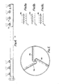
- a support beam l4 extends diametrically across the top of the tank l and carries a motor l5 connected through gear box l6 to rotate a downwardly-extending shaft l7 (the rotation being normally clockwise as viewed in Fig. 2).
- the shaft l7 is located on the vertical axis of the tank and terminates just above the screen 7.
- On this lower end of the shaft l7 are mounted three horizontal spray bars l8 each of which extends from the shaft in a generally radial direction.
- Each bar l8 has a series of nozzles l9 (Fig. 4) and is supplied with water via the shaft l7 from a conduit 29.
- Each bar l8 has an angled portion 20 at its inner end, which is joined to the shaft l7, and a much longer straight portion 2l on which the nozzles are located.
- Fig. 4 shows one of the straight portions 2l and it can be seen that the nozzles l9 are iclined to the axis of the bar l8, the inclination being such that (as indicated in Figs. l and 2) the spray of water from the nozzles is directed both forwards in the direction of movement of the bar and inwards towards the centre of the screen 7.
- the liquid to be filtered is fed to the tank l through the inlet pipe 2 and fills the annular space between the tank wall and the inner container 4, whereupon it flows over the wall of the inner container and on to the screen 7.
- the shaft l7 is rotated and water is supplied to the spray bars l8.
- the liquid being filtered, together with any very fine particles, passes through the screen and collects in the dish-shaped floor 5 of the tank from where it runs out through the outlet pipe l0. Solids remain on the screen 7 and are directed, by the spray of water from the rotating bars l8, towards the centre of the screen where they pass through the centre opening 8 and into the outlet pipe 6 for collection and subsequent disposal.
- Each of the nozzles l9 has a respective impact area on the screen 7 but is not necessarily equally effective over the whole of that area.
- the spray nozzles l9 on each of the bars l8 are so arranged that the impact areas of those nozzles do not follow exactly the same circular paths as the impact areas of the nozzles of the preceding bar. Rather, the circular paths are staggered, this being achieved, as illustrated in Figs.
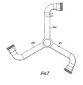
- Fig. 7 shows the angled portions 20 a , b and c of the spray bars l8 a , b and c .
- the radially-extending arm of of portion 20 b is shorter by a small length than d than that of the portion 20 a while that of the portion 20 c is shorter by a length 2 d , the distance d being less than the spacing of the nozzles on the bars: typically, if the length of the radially-extending arm of portion 20 a is 230mm, the length d is l3mm compared with a typical nozzle spacing of 82.5 mm.
- the spray bars need not have the particular shape illustrated in Fig. 2 although this shape does facilitate the staggering of the nozzles.
- the bars could, for example, have the arcuate shape shown in Fig. 8 or could have arcuate inner portions 22 as shown in Fig. 9 rather than the angled inner portions 20.
- it is not essential to employ three spray bars as illustrated and that any appropriate number of bars can be used.
- an arrangement can be provided in which cleaning water is directed at the screen from one or more nozzle which not only rotates about, but can also be moved towards or away from, the centre of the screen 7 to provide a succession of displaced impact areas. Through an appropriate choice of the displacement of successive impact areas, coverage of the screen comparable with that provided by the shower bar arrangement of Fig. 2 can be achieved.
- the spray bars l8 are located below, rather than above, the screen 7 and direct water upwards through the screen to urge the solids towards the central opening 8.
- a so-called distributor plate can be located at the top of the inner container 4, above the spray bars l8 to distribute the liquid to be filtered before it falls onto the screen 7.
- This plate can, for example, be a substantially flat plate with perforations and will, in addition, serve to weaken the impact of the liquid on the screen 7 and can also be used to prevent the liquid swirling on the screen.
- a cover can be provided for the tank l.
Landscapes
- Chemical & Material Sciences (AREA)
- Chemical Kinetics & Catalysis (AREA)
- Engineering & Computer Science (AREA)
- Mechanical Engineering (AREA)
- Paper (AREA)
- Filtration Of Liquid (AREA)
Applications Claiming Priority (2)
| Application Number | Priority Date | Filing Date | Title |
|---|---|---|---|
| GB868602365A GB8602365D0 (en) | 1986-01-31 | 1986-01-31 | Filtering devices |
| GB8602365 | 1986-01-31 |
Publications (2)
| Publication Number | Publication Date |
|---|---|
| EP0232128A2 true EP0232128A2 (de) | 1987-08-12 |
| EP0232128A3 EP0232128A3 (de) | 1988-07-13 |
Family
ID=10592276
Family Applications (1)
| Application Number | Title | Priority Date | Filing Date |
|---|---|---|---|
| EP87300772A Withdrawn EP0232128A3 (de) | 1986-01-31 | 1987-01-29 | Filtrationsanlage |
Country Status (3)
| Country | Link |
|---|---|
| EP (1) | EP0232128A3 (de) |
| FI (1) | FI870409A7 (de) |
| GB (1) | GB8602365D0 (de) |
Cited By (4)
| Publication number | Priority date | Publication date | Assignee | Title |
|---|---|---|---|---|
| US5152891A (en) * | 1990-09-13 | 1992-10-06 | T/M Industrial Supply, Inc. | Self-cleaning strainer |
| EP0522227A1 (de) * | 1991-07-10 | 1993-01-13 | Thermo Fibertek Inc. | Vakuumsieb |
| WO1995018663A1 (en) * | 1994-01-04 | 1995-07-13 | Thermo Fibertek Inc. | Improved strainer |
| CN119971580A (zh) * | 2025-04-11 | 2025-05-13 | 泉州市六源印染织造有限公司 | 面料去异味功能的光触媒制备设备及面料 |
Family Cites Families (3)
| Publication number | Priority date | Publication date | Assignee | Title |
|---|---|---|---|---|
| AT193713B (de) * | 1942-01-13 | 1957-12-10 | Nils Walfrid Joensson | Vorrichtung zum Sieben, Entwässern oder Waschen von Faserstoffaufschwemmungen |
| DE952492C (de) * | 1953-02-12 | 1956-11-15 | Ernst Gustav Drautz | Sortierer, Knoten-, Ast- und Splitterfaenger fuer die Papier-, Pappen-, Faserplatten-, Holzstoff- und Zellstoff-Industrie |
| AT338608B (de) * | 1974-10-11 | 1977-09-12 | Voith Gmbh J M | Vorrichtung zum ausscheiden von grobstoff aus faserstoffaufschwemmungen |
-
1986
- 1986-01-31 GB GB868602365A patent/GB8602365D0/en active Pending
-
1987
- 1987-01-29 EP EP87300772A patent/EP0232128A3/de not_active Withdrawn
- 1987-01-30 FI FI870409A patent/FI870409A7/fi not_active Application Discontinuation
Cited By (6)
| Publication number | Priority date | Publication date | Assignee | Title |
|---|---|---|---|---|
| US5152891A (en) * | 1990-09-13 | 1992-10-06 | T/M Industrial Supply, Inc. | Self-cleaning strainer |
| EP0522227A1 (de) * | 1991-07-10 | 1993-01-13 | Thermo Fibertek Inc. | Vakuumsieb |
| US5259955A (en) * | 1991-07-10 | 1993-11-09 | Bolton Joseph A | Vacuum strainer |
| WO1995018663A1 (en) * | 1994-01-04 | 1995-07-13 | Thermo Fibertek Inc. | Improved strainer |
| US5453193A (en) * | 1994-01-04 | 1995-09-26 | Thermo Fibertek Inc. | Strainer |
| CN119971580A (zh) * | 2025-04-11 | 2025-05-13 | 泉州市六源印染织造有限公司 | 面料去异味功能的光触媒制备设备及面料 |
Also Published As
| Publication number | Publication date |
|---|---|
| FI870409L (fi) | 1987-08-01 |
| FI870409A7 (fi) | 1987-08-01 |
| FI870409A0 (fi) | 1987-01-30 |
| EP0232128A3 (de) | 1988-07-13 |
| GB8602365D0 (en) | 1986-03-05 |
Similar Documents
| Publication | Publication Date | Title |
|---|---|---|
| EP0048091B1 (de) | Vorrichtung zum Entfernen von Ablagerungen | |
| EP0193565B1 (de) | Wasserkläranlage | |
| US5464542A (en) | Method and device for filtering and backwashing solid particles out of liquids | |
| FI90500C (fi) | Ennaltamäärättyä suurikokoisemman hienojakoisen aineen poistoon tarkoitettu vedenselkeytyslaitteisto | |
| DE2427718C2 (de) | Zentrifuge zum Trennen von Flüssigkeiten und Feststoffpartikeln | |
| HUE026311T2 (en) | Painting cabinet equipped with cleaning equipment | |
| US9427681B2 (en) | Multi-purpose self-cleaning filter system | |
| US7077957B2 (en) | Overflow screening device | |
| EP0232128A2 (de) | Filtrationsanlage | |
| US5176835A (en) | Apparatus for continuous purification of liquids | |
| US5582742A (en) | Rotary distribution pipe assembly | |
| JPH10501461A (ja) | 撒水装置を有する多管式濾過装置 | |
| JP4041588B2 (ja) | 濾過装置 | |
| EP0253605B1 (de) | Spritzrohr | |
| EP0478762B1 (de) | Verfahren und vorrichtung zum trennen einer fasersuspension | |
| CA2156715C (en) | Improved strainer | |
| JP7846638B2 (ja) | ストレーナ及び濾過装置 | |
| EP0616829A2 (de) | Filter für Flüssigkeiten mit festen suspendierten Partikeln, insbesondere für Schmier- und Kühlflüssigkeit in Maschinenwerkzeugen | |
| KR100775287B1 (ko) | 오일 새퍼레이터 부유이물 슬러지 연속 자동 제거장치 | |
| GB2121325A (en) | Cleaning centrifuge | |
| SE433073B (sv) | Anordning for rening av flytande medier, sasom avloppsvatten | |
| KR0182391B1 (ko) | 현탁액 분별 장치 | |
| JPH0463721B2 (de) | ||
| KR860001380B1 (ko) | 액체 여과장치 | |
| KR100642654B1 (ko) | 하수 및 오수 처리장의 침사처리시스템 |
Legal Events
| Date | Code | Title | Description |
|---|---|---|---|
| PUAI | Public reference made under article 153(3) epc to a published international application that has entered the european phase |
Free format text: ORIGINAL CODE: 0009012 |
|
| AK | Designated contracting states |
Kind code of ref document: A2 Designated state(s): DE FR GB SE |
|
| PUAL | Search report despatched |
Free format text: ORIGINAL CODE: 0009013 |
|
| AK | Designated contracting states |
Kind code of ref document: A3 Designated state(s): DE FR GB SE |
|
| STAA | Information on the status of an ep patent application or granted ep patent |
Free format text: STATUS: THE APPLICATION IS DEEMED TO BE WITHDRAWN |
|
| 18D | Application deemed to be withdrawn |
Effective date: 19890116 |
|
| RIN1 | Information on inventor provided before grant (corrected) |
Inventor name: HUDON, JAMES DENIS |