EP0233113A1 - Werkstückauswerfer- und -auswerferrückstellvorrichtung in einer Spritzgiessmaschine - Google Patents
Werkstückauswerfer- und -auswerferrückstellvorrichtung in einer Spritzgiessmaschine Download PDFInfo
- Publication number
- EP0233113A1 EP0233113A1 EP87400174A EP87400174A EP0233113A1 EP 0233113 A1 EP0233113 A1 EP 0233113A1 EP 87400174 A EP87400174 A EP 87400174A EP 87400174 A EP87400174 A EP 87400174A EP 0233113 A1 EP0233113 A1 EP 0233113A1
- Authority
- EP
- European Patent Office
- Prior art keywords
- assembly
- ejector
- ejection
- ejection assembly
- male
- Prior art date
- Legal status (The legal status is an assumption and is not a legal conclusion. Google has not performed a legal analysis and makes no representation as to the accuracy of the status listed.)
- Granted
Links
Images



Classifications
-
- F—MECHANICAL ENGINEERING; LIGHTING; HEATING; WEAPONS; BLASTING
- F16—ENGINEERING ELEMENTS AND UNITS; GENERAL MEASURES FOR PRODUCING AND MAINTAINING EFFECTIVE FUNCTIONING OF MACHINES OR INSTALLATIONS; THERMAL INSULATION IN GENERAL
- F16B—DEVICES FOR FASTENING OR SECURING CONSTRUCTIONAL ELEMENTS OR MACHINE PARTS TOGETHER, e.g. NAILS, BOLTS, CIRCLIPS, CLAMPS, CLIPS OR WEDGES; JOINTS OR JOINTING
- F16B21/00—Means for preventing relative axial movement of a pin, spigot, shaft or the like and a member surrounding it; Stud-and-socket releasable fastenings
- F16B21/10—Means for preventing relative axial movement of a pin, spigot, shaft or the like and a member surrounding it; Stud-and-socket releasable fastenings by separate parts
- F16B21/16—Means for preventing relative axial movement of a pin, spigot, shaft or the like and a member surrounding it; Stud-and-socket releasable fastenings by separate parts with grooves or notches in the pin or shaft
- F16B21/165—Means for preventing relative axial movement of a pin, spigot, shaft or the like and a member surrounding it; Stud-and-socket releasable fastenings by separate parts with grooves or notches in the pin or shaft with balls or rollers
-
- B—PERFORMING OPERATIONS; TRANSPORTING
- B29—WORKING OF PLASTICS; WORKING OF SUBSTANCES IN A PLASTIC STATE IN GENERAL
- B29C—SHAPING OR JOINING OF PLASTICS; SHAPING OF MATERIAL IN A PLASTIC STATE, NOT OTHERWISE PROVIDED FOR; AFTER-TREATMENT OF THE SHAPED PRODUCTS, e.g. REPAIRING
- B29C45/00—Injection moulding, i.e. forcing the required volume of moulding material through a nozzle into a closed mould; Apparatus therefor
- B29C45/17—Component parts, details or accessories; Auxiliary operations
- B29C45/1775—Connecting parts, e.g. injection screws, ejectors, to drive means
-
- B—PERFORMING OPERATIONS; TRANSPORTING
- B29—WORKING OF PLASTICS; WORKING OF SUBSTANCES IN A PLASTIC STATE IN GENERAL
- B29C—SHAPING OR JOINING OF PLASTICS; SHAPING OF MATERIAL IN A PLASTIC STATE, NOT OTHERWISE PROVIDED FOR; AFTER-TREATMENT OF THE SHAPED PRODUCTS, e.g. REPAIRING
- B29C45/00—Injection moulding, i.e. forcing the required volume of moulding material through a nozzle into a closed mould; Apparatus therefor
- B29C45/17—Component parts, details or accessories; Auxiliary operations
- B29C45/40—Removing or ejecting moulded articles
- B29C45/4005—Ejector constructions; Ejector operating mechanisms
Definitions
- the subject of the present invention is a device for ejecting and recalling the ejection of a part which can be used in particular, but not exclusively, in molding or shaping machines, such as extruders or molding presses for example. .
- the ejection of the finished part in the molding machines is generally done as follows: the part to be produced is molded between a first half-shell, fixed relative to the frame of the machine, and a second half-shell mounted at the upper part of a set movable relative to the frame. On this mobile assembly is mounted an ejection assembly which can move relative to the latter and comprises one or more ejection rods, the upper part of which passes through the second half-shell and is in contact with the lower part of the part. molded. When this is finished, the mobile assembly is lowered until the ejection assembly abuts on one or more ejectors fixed relative to the frame of the machine.
- a first type of machine there is a single ejector placed along the axis of the machine (in fact, this generally has a symmetry of revolution) while, in a second type of machine, there are several ejectors regularly distributed around this axis.
- the mobile assembly continuing its downward stroke, this has the effect that the upper part of the ejection rods disengages from the mobile assembly and from the second half-shell, which allows the ejection of the part. Then the movable assembly is raised, which again drives the ejection assembly during this movement.
- an ejection reminder must be provided because the ejection assembly does not automatically return by gravity to its initial position relative to the movable assembly because of friction or possible misalignments.
- Several devices have been proposed to carry out this recall. For example, cylinders mounted on the mobile assembly and acting on the ejection assembly have been used: such a device is complex, therefore expensive, and, moreover, considerably makes the machine heavier.
- the molding machine bearing the general reference 2
- the actual mold consists of two half-shells, namely a first half-shell 8, fixed to the upper part of the frame of the machine, and a second half-shell 10 fixed to the upper part of the movable assembly 6
- a thermoset plastic sand or thermoplastic is transferred or injected through line 12 and the part 14 is formed between the half-shells 8 and 10.
- the part 14 is solidified, it is necessary to extract it from the mold.
- an ejection assembly is used, bearing the general reference 16, which consists of a base 18 resting on the base 20 of the mobile assembly and two, or more, ejection rods 22. These latter pass through the upper part of the movable assembly 6, as well as the half-shell 10 of the mold, the upper part of the rods 22 being in contact with the part 14.
- the extraction of the part 14 is done in the following way:
- the movable assembly 6 is set in motion downward until the ejection assembly abuts against two or more ejectors 24 fixed on the frame of the machine , in the lower part of it. This has the effect of blocking the movement of the ejection assembly while the mobile assembly 6 continues to descend.
- FIG. 1b in which the mobile assembly 6 has reached the end of the race, in the low position, while the ejection assembly 16 is in abutment against the ejectors 24.
- the rods 22 exit outside the half-shell 10 and the part 14 can be extracted easily.
- the mobile assembly 6 is then set in movement upwards, until it again comes into abutment against the lower part of the ejection assembly 16.
- the devices of this type are satisfactory in the case of machines with a single ejector, they have very significant drawbacks in the case of machines with several ejectors.
- the ejectors are originally placed on the machine frame, the subsequent mounting of the corresponding elements on the ejection assembly is a very delicate operation and it is very difficult, if not impossible, to obtain perfect alignment between the ejectors and the elements placed on the ejection assembly.
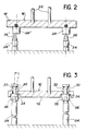
- FIG. 2 is an enlarged schematic view, in vertical section, illustrating the coupling means between the ejectors and the ejection assembly.
- the coupling devices comprise, for example, a male part 26 fixed to the upper part of the ejector 24 and a female part 28 fixed to the base 18 of the ejection assembly 16.
- the coupling devices comprise, for example, a male part 26 fixed to the upper part of the ejector 24 and a female part 28 fixed to the base 18 of the ejection assembly 16.
- the ejectors 24 fitted with parts 26 must be adjusted so that all of the devices operate simultaneously during uncoupling. It could indeed happen that one of the devices is in traction while the others are free, the base 18 being in abutment, which risks seriously damaging the couplers. Obtaining strictly simultaneous operation of the various couplers would require very precise height adjustment of the ejectors 24, which is practically impossible to achieve. Also, because of all these drawbacks (difficulty in aligning the centers of the couplers and correct height adjustment of the ejectors), the use of commercial automatic couplers was stopped in machines with several ejectors in order to use systems again. complexes such as jacks.
- the object of the present invention is to eliminate these drawbacks by proposing a device for ejecting and recalling the ejection of a part into a machine which makes it possible to use automatic couplings on the market even in the event of misalignment different parts of the machine.
- the device which is the subject of the invention comprises, in a known manner: - at least one ejector fixed relative to the machine frame, - a mobile assembly mounted on the frame of the machine and able to move along this frame, - an ejection assembly mounted on said mobile assembly and able to move relative thereto, - coupling means between said ejector and the ejection assembly in order to immobilize the latter while the mobile assembly continues to move, said coupling means comprising a male part mounted on the ejector or the ejection assembly and a female part mounted on the ejection assembly or the ejector.
- At least one of the male or female parts is mounted on the element which supports it by means of fixing means allowing a limited relative clearance between said part and said element, these fixing means comprising elastic means for returning said part and said element to a force transmission position, these elastic means being located between said part and said element and compressing before the unlocking of the coupling means.
- the male part is always locked on the female part, even if there is a certain misalignment between the axes of the two parts.
- the male part is mounted on the ejector, the female part is mounted on the ejection assembly, but it would not go beyond the scope of the invention to reverse the position of the parts, the male part being mounted on the mobile assembly and the female part on the ejector.
- the expression "towards a force transmission position” it means that the elastic return means are mounted so as to push the mounted part with a relative clearance in the direction in which it is pushed at the time of coupling.
- the two male and female parts exert a force on each other and the one which is fixed, for example the male part, tends to push the other in a certain direction.
- the female part is mounted with a certain clearance on the ejection assembly, at the time of coupling, it is pushed against the ejection assembly.
- the part which is freely mounted is mounted on the ejection assembly and comprises a cylindrical part located in a cylindrical hole of the ejection assembly, the diameter of the hole being greater than that of said part cylindrical, which thus allows a radial clearance.
- said part is movable between two stops provided on the ejection assembly, which allows axial play.
- the elastic return means apply said part to one of the two stops.
- the male part is mounted on the ejector and it is fixed relative to the latter, while the female part is mounted on the ejection assembly by means of fixing means allowing limited relative travel.
- the male part and the female part have chamfers in order to facilitate coupling.
- the part female 28 is fixed to the lower end of a connecting pin 30.
- the latter is cylindrical and passes inside a hole 34, also cylindrical, provided in the base 18 of the ejection assembly 16.
- the diameter of the hole 34 is greater than that of the connecting axis 30, which allows a certain radial movement.
- the assembly formed by the connecting axis 30 and the female part 28 rests on the base 18 of the movable assembly 16 by means of elastic means 32, which allows a certain axial movement.
- the left side of Figure 3 that in case of misalignment between the ejector 24 and the female part 28, the latter can move laterally and / or pivot around an axis perpendicular to the plane of the figure, this which allows locking.
- the coupling means appear better on the sectional view of FIG. 4, where we find the male part 26 screwed into the upper part of the ejector 24.
- the female part 28 is screwed in the connecting axis 30, while the elastic means 32 consist of a stack of washers disposed between the upper part of the base 18 of the ejection assembly 16 and the head 33 of the connection axis 30.
- the washers 32 push the connection axis upwards, which has the effect of applying the female part 28 against a stop 37.
- the base 18 of the ejection assembly 16 consists of a plate 17 and a counter plate 19, the stop 37 being constituted by the underside of the plate 17.
- the male part 26 tends to push the female part 28 towards the stop 37.
- the force transmission at the time of the coupling therefore tends to apply the female part against the stop 37 and the means elastic 32 are indeed means for returning the part 28 to the force transmission position.
- the elastic means 32 are not located between the ejection assembly 16 and the female part 28 proper, but between the assembly 16 and the head 33 of the connecting axis 30.
- this axis is rigidly linked to the part 28 and the assembly formed by these two parts can be considered to be the female part: it can therefore be considered that the elastic means 32 are located between the ejection assembly 16 and the female part.
- the male part exerts on the female part a downward force and the latter tends to move away from the stop 37.
- a socket 52 mounted on the female part 28 and equipped with a flange 36.
- the flange 36 comes into contact with a stop 38 provided on the part 40, which has the effect of stopping the movement downwards and allowing unlocking.
- the part 40 is fixed to the base 18 of the ejection assembly 16 using one or more screws 42, but it would not go beyond the scope of the invention to use a different arrangement, the stop 38 being provided directly on the base 18.
- the passage 34 formed in the base 18 of the ejection assembly 16, in which the connecting axis can move radially with limited clearance.
- the part 40 is also provided with a passage 41 in which the female part 28 and the sleeve 52 are located.
- the latter is cylindrical and the diameter of the passage 41 is greater than that of the sleeve 52 in order to allow the radial movement.
- the axial travel is limited by the stops 37 and 38.
- the male part 26 has at its upper part a chamfer 44 which can cooperate with a chamfer 46 provided at the lower part of the female part in order to facilitate penetration.
- the male part 26 also includes a groove 48 which can cooperate with rollers 50 in order to ensure locking, as is better seen in FIGS. 5 and 6.
- the sleeve or outer ring 52 is mounted around the female part 28 by means of a spring 54, one end of which bears on the part 28 and the other on a washer 70 (FIG. 5).
- the latter can abut on a face 71 of the ring 52 and keeps the rollers 50 in slides 65 formed in the female part 28 and inclined relative to the axis thereof.
- a circlip 66 mounted on the lower part of the female part 28 limits the relative movement between the latter and the ring 52.
- FIG. 5 shows the elements of the device still in the locked position, but just before unlocking begins when the mobile assembly is raised.
- the washers 32 are compressed and the upper part of the part 28 is no longer in contact with the stop 37.
- the socket 52 which previously rested on the circlip 66 is urged upward by the movement of the base 18 of the ejection assembly: it is no longer its lower part which rests on the circlip 66, but its flange 36 which rests on the stop 38.
- the rollers 50 they are pushed down by the washer 70 and the spring 54 and locked in the groove 48 of the part 26.
- the male part acts on the rollers 50, which has the effect of driving the female part 28 down until it reaches the position illustrated in FIG. 5.
- the washer 70 which is in abutment on the face 71 of the ring 52, gradually releases the rollers 50 which rise in the slides 65 during the relative movement of the parts 28 and 26, thus ensuring the unlocking of the ejection assembly when the rollers 50 have come out of the groove 48.
- the washers 32 again apply the upper part of the part 28 against the stop 37 and the spring 54 pushes the part 52 down via the washer 70.
- the ring 52 rests on the circlip 66 and the flange 36 is no longer in contact with the stop 38.
- the rollers 50 they are again pushed to the bottom of the slides 65 by the washer 70 under the effect spring 54.
- the slides 65 are simple slots of limited length made in the wall of the part 28 so that the rollers 50 abut at the bottom of the slides like the roller 50a in FIG. 6.
- This figure represents the other roller 50b in the process of locking or unlocking, that is to say distant from the bottom of the slide 65.
- housings 51 shown schematically in phantom in Figure 6
- the rollers 50 can move radially in the slides 65 while remaining parallel to themselves.
- the male part is mounted on the ejector and it is fixed while the female part is mounted on the ejection assembly with an axial clearance and a radial clearance, but other arrangements are possible without departing from the scope of the invention.
- FIGS. 7a to 7d the male part 26 is mounted on the ejector and the female part 28 on the ejection assembly.
- FIG. 7a illustrates the previously described case where the male part 26 is fixed and the female part 28 movable axially and radially.
- FIG. 7b it is the female part which is fixed and the male part which is movable in the radial direction and in the axial direction.
- FIG. 7c the male part is movable in the radial direction and the female part in the axial direction and, in the case of FIG. 7d, it is the male part which is movable in the axial direction and the female part in the radial direction.
- Figures 8a to 8d show the different mounting possibilities with the female part 28 on the ejector and the male part 26 on the ejection assembly.
- the female part is fixed and the part male movable axially and radially while, in the case of FIG. 8b, it is the male part which is fixed and the female part which is movable in both directions.
- the female part is movable radially and the male part axially.
- FIG. 8d it is the female part which is axially movable and the male part radially.
- the device which is the subject of the invention has interesting advantages since it allows easy locking and unlocking of the ejection assembly on the ejectors, even if there is a slight misalignment between the ejectors and the nozzles mounted on the ejection assembly. This eliminates the risk of degradation that could exist if one of the elements was in traction, the others being free.
- the disconnection time differences due mainly to the construction defects inherent in any mechanical device are compensated by the elastic system 32 which more or less crashes before unlocking. Once unlocked, the female part abuts against the ejection assembly under the effect of the elastic means.
- the device which is the subject of the invention applies more particularly to machines with several ejectors by making it possible to eliminate the complex return systems of the prior art, it can also be used on machines with a single ejector. Indeed, even if the rigid assembly is satisfactory in this type of machine, the use of the device object of the invention improves the use of commercial couplers because it is no longer necessary to have very high precision in the mounting.
Landscapes
- Engineering & Computer Science (AREA)
- Mechanical Engineering (AREA)
- Manufacturing & Machinery (AREA)
- General Engineering & Computer Science (AREA)
- Injection Moulding Of Plastics Or The Like (AREA)
- Vending Machines For Individual Products (AREA)
- Moulds For Moulding Plastics Or The Like (AREA)
- Threshing Machine Elements (AREA)
- Feeding Of Articles To Conveyors (AREA)
- Massaging Devices (AREA)
Priority Applications (1)
| Application Number | Priority Date | Filing Date | Title |
|---|---|---|---|
| AT87400174T ATE44355T1 (de) | 1986-01-30 | 1987-01-26 | Werkstueckauswerfer- und auswerferr¨ckstellvorrichtung in einer spritzgiessmaschine. |
Applications Claiming Priority (2)
| Application Number | Priority Date | Filing Date | Title |
|---|---|---|---|
| FR8601299A FR2593436B1 (fr) | 1986-01-30 | 1986-01-30 | Dispositif d'ejection et de rappel d'ejection d'une piece dans une machine |
| FR8601299 | 1986-01-30 |
Publications (2)
| Publication Number | Publication Date |
|---|---|
| EP0233113A1 true EP0233113A1 (de) | 1987-08-19 |
| EP0233113B1 EP0233113B1 (de) | 1989-07-05 |
Family
ID=9331640
Family Applications (1)
| Application Number | Title | Priority Date | Filing Date |
|---|---|---|---|
| EP87400174A Expired EP0233113B1 (de) | 1986-01-30 | 1987-01-26 | Werkstückauswerfer- und -auswerferrückstellvorrichtung in einer Spritzgiessmaschine |
Country Status (5)
| Country | Link |
|---|---|
| EP (1) | EP0233113B1 (de) |
| AT (1) | ATE44355T1 (de) |
| DE (1) | DE3760292D1 (de) |
| FR (1) | FR2593436B1 (de) |
| PT (1) | PT84220B (de) |
Cited By (7)
| Publication number | Priority date | Publication date | Assignee | Title |
|---|---|---|---|---|
| DE4103446A1 (de) * | 1991-02-01 | 1992-08-13 | Mannesmann Ag | Vorrichtung zum auswerfen von formteilen aus einer spritzgiessmaschine |
| ES2083903A2 (es) * | 1993-05-11 | 1996-04-16 | Pruna Alberto Navarra | Pinza automatica de sujecion para cambio rapido, preferentemente, de los tubulares de expulsion en moldes de inyeccion. |
| WO2001031990A1 (en) * | 1999-11-03 | 2001-05-10 | Sipa S.P.A. | Actuating rod for mould-carrying plate |
| EP1410890A1 (de) * | 2002-10-11 | 2004-04-21 | Tung-Jung Chen | Auswerferkupplung für ein Spritzgiesswerkzeug |
| DE102018217550A1 (de) * | 2018-10-12 | 2020-04-16 | Volkswagen Aktiengesellschaft | Dauerform und Verfahren zur Herstellung eines Bauteils |
| WO2020201735A1 (en) * | 2019-04-05 | 2020-10-08 | Berkeley Modular Limited | Post connector and peg |
| IT202000020611A1 (it) * | 2020-08-28 | 2022-02-28 | Bongioanni Macch S P A | Dispositivo di bloccaggio per il fissaggio di uno stampo ad un’unità porta-stampo e stampo comprendente detto dispositivo di bloccaggio |
Families Citing this family (3)
| Publication number | Priority date | Publication date | Assignee | Title |
|---|---|---|---|---|
| DE19739012A1 (de) * | 1997-09-06 | 1999-03-18 | Euchner Gmbh & Co | Vorrichtung zum Befestigen eines Winkelgebers |
| CN103879025B (zh) * | 2012-12-20 | 2015-12-09 | 上海工程技术大学 | 一种外置式液压机顶出限位控制装置 |
| CN109016633A (zh) * | 2018-08-09 | 2018-12-18 | 湖北久鸣汽车零部件有限公司 | 一种离合器面片多工位自动顶出机构 |
Citations (5)
| Publication number | Priority date | Publication date | Assignee | Title |
|---|---|---|---|---|
| US3252180A (en) * | 1963-06-26 | 1966-05-24 | Houk Machine Co | Adjustable grip for ejector mechanism in an injection mold |
| FR1568601A (de) * | 1967-11-14 | 1969-05-23 | ||
| US3448488A (en) * | 1967-01-11 | 1969-06-10 | Beloit Eastern Corp | Quick adjustment knock-out rod |
| FR2355592A1 (fr) * | 1976-06-21 | 1978-01-20 | Norimex Marketing Import Expor | Dispositif d'accouplement, notamment entre la plaque d'ejection d'un moule et une tige d'actionnement, sur une machine a mouler par injection |
| DE3309707A1 (de) * | 1983-03-18 | 1984-09-20 | Hans-Joachim 4971 Hüllhorst Meyke | Auswerfer-ankopplung fuer formen der kunststoffverarbeitung |
-
1986
- 1986-01-30 FR FR8601299A patent/FR2593436B1/fr not_active Expired
-
1987
- 1987-01-26 EP EP87400174A patent/EP0233113B1/de not_active Expired
- 1987-01-26 DE DE8787400174T patent/DE3760292D1/de not_active Expired
- 1987-01-26 AT AT87400174T patent/ATE44355T1/de not_active IP Right Cessation
- 1987-01-29 PT PT84220A patent/PT84220B/pt not_active IP Right Cessation
Patent Citations (5)
| Publication number | Priority date | Publication date | Assignee | Title |
|---|---|---|---|---|
| US3252180A (en) * | 1963-06-26 | 1966-05-24 | Houk Machine Co | Adjustable grip for ejector mechanism in an injection mold |
| US3448488A (en) * | 1967-01-11 | 1969-06-10 | Beloit Eastern Corp | Quick adjustment knock-out rod |
| FR1568601A (de) * | 1967-11-14 | 1969-05-23 | ||
| FR2355592A1 (fr) * | 1976-06-21 | 1978-01-20 | Norimex Marketing Import Expor | Dispositif d'accouplement, notamment entre la plaque d'ejection d'un moule et une tige d'actionnement, sur une machine a mouler par injection |
| DE3309707A1 (de) * | 1983-03-18 | 1984-09-20 | Hans-Joachim 4971 Hüllhorst Meyke | Auswerfer-ankopplung fuer formen der kunststoffverarbeitung |
Cited By (11)
| Publication number | Priority date | Publication date | Assignee | Title |
|---|---|---|---|---|
| DE4103446A1 (de) * | 1991-02-01 | 1992-08-13 | Mannesmann Ag | Vorrichtung zum auswerfen von formteilen aus einer spritzgiessmaschine |
| EP0497437A3 (en) * | 1991-02-01 | 1993-01-27 | Mannesmann Aktiengesellschaft | Apparatus for ejecting moulded pieces from an injection moulding machine |
| US5252057A (en) * | 1991-02-01 | 1993-10-12 | Mannesmann Aktiengesellschaft | Apparatus for ejecting moldings from an injection molding machine |
| ES2083903A2 (es) * | 1993-05-11 | 1996-04-16 | Pruna Alberto Navarra | Pinza automatica de sujecion para cambio rapido, preferentemente, de los tubulares de expulsion en moldes de inyeccion. |
| WO2001031990A1 (en) * | 1999-11-03 | 2001-05-10 | Sipa S.P.A. | Actuating rod for mould-carrying plate |
| EP1410890A1 (de) * | 2002-10-11 | 2004-04-21 | Tung-Jung Chen | Auswerferkupplung für ein Spritzgiesswerkzeug |
| DE102018217550A1 (de) * | 2018-10-12 | 2020-04-16 | Volkswagen Aktiengesellschaft | Dauerform und Verfahren zur Herstellung eines Bauteils |
| DE102018217550B4 (de) * | 2018-10-12 | 2026-01-15 | Volkswagen Aktiengesellschaft | Dauerform und Verfahren zur Herstellung eines Bauteils |
| WO2020201735A1 (en) * | 2019-04-05 | 2020-10-08 | Berkeley Modular Limited | Post connector and peg |
| IT202000020611A1 (it) * | 2020-08-28 | 2022-02-28 | Bongioanni Macch S P A | Dispositivo di bloccaggio per il fissaggio di uno stampo ad un’unità porta-stampo e stampo comprendente detto dispositivo di bloccaggio |
| EP3960409A1 (de) | 2020-08-28 | 2022-03-02 | Bongioanni Macchine S.p.A. | Sperrvorrichtung und verfahren zum befestigen einer schalung an einer schalungshalteeinheit, und schalung die die genannte sperrvorrichtung umfasst |
Also Published As
| Publication number | Publication date |
|---|---|
| FR2593436B1 (fr) | 1989-06-30 |
| PT84220B (pt) | 1993-05-31 |
| DE3760292D1 (en) | 1989-08-10 |
| EP0233113B1 (de) | 1989-07-05 |
| PT84220A (pt) | 1987-09-18 |
| ATE44355T1 (de) | 1989-07-15 |
| FR2593436A1 (fr) | 1987-07-31 |
Similar Documents
| Publication | Publication Date | Title |
|---|---|---|
| EP0233113B1 (de) | Werkstückauswerfer- und -auswerferrückstellvorrichtung in einer Spritzgiessmaschine | |
| FR2608546A1 (fr) | Mecanisme d'accouplement d'organes d'articulation de porte sur une coque d'automobile | |
| FR2473404A1 (fr) | Moule a injection, en particulier pour matieres synthetiques ou moule a compression | |
| EP0743053A1 (de) | Sicherheits- und Kontrollvorrichtung der Verriegelung einer Radnabe, insbesondere für Rollstuhl | |
| WO2001086189A1 (fr) | Dispositif de raccordement d'un embout a un organe | |
| FR2626062A1 (fr) | Systeme de verrouillage et de deverrouillage d'une lampe sur un porte-lampe, plus particulierement pour un dispositif d'eclairage ou de signalisation notamment de vehicule automobile | |
| EP3210746A1 (de) | Vorrichtung zum entformen mittels kettenartige verbundener elemente | |
| EP0749135B1 (de) | Bedienungstaste mit Verriegelung, insbesondere zur Bedienung einer elektrische Komponente | |
| WO1993022165A1 (fr) | Dispositif de securite, notamment anti-vol pour volant de direction de vehicule automobile | |
| FR2762557A1 (fr) | Article comportant deux elements articules l'un par rapport a l'autre | |
| FR2677086A1 (fr) | Commande par cable en deux parties et procede de montage d'une telle commande. | |
| EP3976986A1 (de) | Vorrichtung zum kuppeln zweier wellen sowie mit einer solchen kupplungsvorrichtung versehene anhängerkupplung | |
| EP0940591B1 (de) | Schnellentkupplungsmechanismus für ein Kugelgelenk | |
| FR2580344A1 (fr) | Dispositif d'accouplement bout a bout de deux barres | |
| EP1555176A1 (de) | Positionier- und Befestigunseinrichtung für zwei mechanische Teile, Fahrzeuganordnung mit einer solchen Einrichtung und Fahrzeug mit einer solchen Anordnung | |
| FR2590633A1 (fr) | Dispositif de fixation reglable, en particulier pour l'assemblage d'ecrans video | |
| EP0214002B1 (de) | Verankerungsvorrichtung einer Gleiteinrichtung mit einer Stecklasche, insbesondere für eine passive Sicherheitsgurtanordnung | |
| FR2717872A1 (fr) | Accouplement destiné à relier un manchon d'accouplement à un bout d'arbre d'accouplement. | |
| FR2813243A1 (fr) | Porte coulissante de vehicule automobile demontable manuellement | |
| FR3065389B1 (fr) | Moule de realisation d'un article moule comprenant un dipositif d'ejection d'une partie tubulaire de l'article moule | |
| EP1346263B1 (de) | Einrichtung zum anbringen eines flexiblen bands insbesondere an einem uhrengehäuse und verfahren zu seiner anbringung | |
| EP0443896B1 (de) | Verschluss mit einem Stator, in welchem ein um mindestens einen Winkelbereich drehbarer, mit einem Mitnehmer rotationsverbundener Rotor angeordnet ist | |
| EP4249843B1 (de) | Vorrichtung zum laden eines geschosses in die kammer einer waffe | |
| FR2569605A1 (fr) | Dispositif d'accouplement debrayable et embrayable automatiquement entre le plateau mobile et la batterie d'ejection de l'outillage d'une presse | |
| EP1587560A1 (de) | Vorrichtung zum halten einer angiographie-spritze und ihre kombination mit einer angiographie-spritze und mit einem angiographie-injektor |
Legal Events
| Date | Code | Title | Description |
|---|---|---|---|
| PUAI | Public reference made under article 153(3) epc to a published international application that has entered the european phase |
Free format text: ORIGINAL CODE: 0009012 |
|
| AK | Designated contracting states |
Kind code of ref document: A1 Designated state(s): AT BE CH DE ES GB IT LI |
|
| 17P | Request for examination filed |
Effective date: 19880121 |
|
| 17Q | First examination report despatched |
Effective date: 19880912 |
|
| GRAA | (expected) grant |
Free format text: ORIGINAL CODE: 0009210 |
|
| AK | Designated contracting states |
Kind code of ref document: B1 Designated state(s): AT BE CH DE ES GB IT LI |
|
| PG25 | Lapsed in a contracting state [announced via postgrant information from national office to epo] |
Ref country code: IT Free format text: LAPSE BECAUSE OF FAILURE TO SUBMIT A TRANSLATION OF THE DESCRIPTION OR TO PAY THE FEE WITHIN THE PRE;WARNING: LAPSES OF ITALIAN PATENTS WITH EFFECTIVE DATE BEFORE 2007 MAY HAVE OCCURRED AT ANY TIME BEFORE 2007. THE CORRECT EFFECTIVE DATE MAY BE DIFFERENT FROM THE ONE RECORDED.SCRIBED TIME-LIMIT Effective date: 19890705 Ref country code: AT Effective date: 19890705 Ref country code: GB Effective date: 19890705 |
|
| REF | Corresponds to: |
Ref document number: 44355 Country of ref document: AT Date of ref document: 19890715 Kind code of ref document: T |
|
| REF | Corresponds to: |
Ref document number: 3760292 Country of ref document: DE Date of ref document: 19890810 |
|
| PG25 | Lapsed in a contracting state [announced via postgrant information from national office to epo] |
Ref country code: ES Free format text: LAPSE BECAUSE OF FAILURE TO SUBMIT A TRANSLATION OF THE DESCRIPTION OR TO PAY THE FEE WITHIN THE PRESCRIBED TIME-LIMIT Effective date: 19891016 |
|
| GBV | Gb: ep patent (uk) treated as always having been void in accordance with gb section 77(7)/1977 [no translation filed] | ||
| PG25 | Lapsed in a contracting state [announced via postgrant information from national office to epo] |
Ref country code: BE Effective date: 19900131 |
|
| PLBE | No opposition filed within time limit |
Free format text: ORIGINAL CODE: 0009261 |
|
| STAA | Information on the status of an ep patent application or granted ep patent |
Free format text: STATUS: NO OPPOSITION FILED WITHIN TIME LIMIT |
|
| 26N | No opposition filed | ||
| BERE | Be: lapsed |
Owner name: AEROSPATIALE SOC. NATIONALE INDUSTRIELLE Effective date: 19900131 |
|
| PGFP | Annual fee paid to national office [announced via postgrant information from national office to epo] |
Ref country code: CH Payment date: 19930113 Year of fee payment: 7 |
|
| PGFP | Annual fee paid to national office [announced via postgrant information from national office to epo] |
Ref country code: DE Payment date: 19930203 Year of fee payment: 7 |
|
| PG25 | Lapsed in a contracting state [announced via postgrant information from national office to epo] |
Ref country code: CH Effective date: 19940131 Ref country code: LI Effective date: 19940131 |
|
| REG | Reference to a national code |
Ref country code: CH Ref legal event code: PL |
|
| PG25 | Lapsed in a contracting state [announced via postgrant information from national office to epo] |
Ref country code: DE Effective date: 19941001 |