EP1555176A1 - Positionier- und Befestigunseinrichtung für zwei mechanische Teile, Fahrzeuganordnung mit einer solchen Einrichtung und Fahrzeug mit einer solchen Anordnung - Google Patents
Positionier- und Befestigunseinrichtung für zwei mechanische Teile, Fahrzeuganordnung mit einer solchen Einrichtung und Fahrzeug mit einer solchen Anordnung Download PDFInfo
- Publication number
- EP1555176A1 EP1555176A1 EP04292772A EP04292772A EP1555176A1 EP 1555176 A1 EP1555176 A1 EP 1555176A1 EP 04292772 A EP04292772 A EP 04292772A EP 04292772 A EP04292772 A EP 04292772A EP 1555176 A1 EP1555176 A1 EP 1555176A1
- Authority
- EP
- European Patent Office
- Prior art keywords
- sleeve
- mechanical part
- integral
- fastening element
- pairs
- Prior art date
- Legal status (The legal status is an assumption and is not a legal conclusion. Google has not performed a legal analysis and makes no representation as to the accuracy of the status listed.)
- Granted
Links
Images



Classifications
-
- B—PERFORMING OPERATIONS; TRANSPORTING
- B60—VEHICLES IN GENERAL
- B60S—SERVICING, CLEANING, REPAIRING, SUPPORTING, LIFTING, OR MANOEUVRING OF VEHICLES, NOT OTHERWISE PROVIDED FOR
- B60S1/00—Cleaning of vehicles
- B60S1/02—Cleaning windscreens, windows or optical devices
- B60S1/04—Wipers or the like, e.g. scrapers
- B60S1/043—Attachment of the wiper assembly to the vehicle
- B60S1/0441—Attachment of the wiper assembly to the vehicle characterised by the attachment means
- B60S1/0447—Attachment of the wiper assembly to the vehicle characterised by the attachment means non-screw fixation, (e.g. snap-in, bayonnet-type..)
-
- B—PERFORMING OPERATIONS; TRANSPORTING
- B60—VEHICLES IN GENERAL
- B60S—SERVICING, CLEANING, REPAIRING, SUPPORTING, LIFTING, OR MANOEUVRING OF VEHICLES, NOT OTHERWISE PROVIDED FOR
- B60S1/00—Cleaning of vehicles
- B60S1/02—Cleaning windscreens, windows or optical devices
- B60S1/04—Wipers or the like, e.g. scrapers
- B60S1/0413—Modular wiper assembly
- B60S1/0422—Modular wiper assembly having a separate transverse element
-
- B—PERFORMING OPERATIONS; TRANSPORTING
- B60—VEHICLES IN GENERAL
- B60S—SERVICING, CLEANING, REPAIRING, SUPPORTING, LIFTING, OR MANOEUVRING OF VEHICLES, NOT OTHERWISE PROVIDED FOR
- B60S1/00—Cleaning of vehicles
- B60S1/02—Cleaning windscreens, windows or optical devices
- B60S1/04—Wipers or the like, e.g. scrapers
- B60S1/043—Attachment of the wiper assembly to the vehicle
- B60S1/0433—Attachement of a wiper modular assembly to the vehicle
-
- B—PERFORMING OPERATIONS; TRANSPORTING
- B60—VEHICLES IN GENERAL
- B60S—SERVICING, CLEANING, REPAIRING, SUPPORTING, LIFTING, OR MANOEUVRING OF VEHICLES, NOT OTHERWISE PROVIDED FOR
- B60S1/00—Cleaning of vehicles
- B60S1/02—Cleaning windscreens, windows or optical devices
- B60S1/04—Wipers or the like, e.g. scrapers
- B60S1/043—Attachment of the wiper assembly to the vehicle
- B60S1/0441—Attachment of the wiper assembly to the vehicle characterised by the attachment means
- B60S1/0444—Attachment of the wiper assembly to the vehicle characterised by the attachment means comprising vibration or noise absorbing means
-
- F—MECHANICAL ENGINEERING; LIGHTING; HEATING; WEAPONS; BLASTING
- F16—ENGINEERING ELEMENTS AND UNITS; GENERAL MEASURES FOR PRODUCING AND MAINTAINING EFFECTIVE FUNCTIONING OF MACHINES OR INSTALLATIONS; THERMAL INSULATION IN GENERAL
- F16B—DEVICES FOR FASTENING OR SECURING CONSTRUCTIONAL ELEMENTS OR MACHINE PARTS TOGETHER, e.g. NAILS, BOLTS, CIRCLIPS, CLAMPS, CLIPS OR WEDGES; JOINTS OR JOINTING
- F16B21/00—Means for preventing relative axial movement of a pin, spigot, shaft or the like and a member surrounding it; Stud-and-socket releasable fastenings
- F16B21/06—Releasable fastening devices with snap-action
- F16B21/07—Releasable fastening devices with snap-action in which the socket has a resilient part
- F16B21/073—Releasable fastening devices with snap-action in which the socket has a resilient part the socket having a resilient part on its inside
Definitions
- the present invention relates to a device for positioning and fixing of a first mechanical part on a second mechanical part, comprising at least three pairs of fasteners, each comprising a first fastening element secured to the first piece mechanical, and a second fastening element secured to the second mechanical part in which one of said pairs forms an elastic snap connection according to one direction, while the other two pairs form bearings providing the first mechanical part a freedom of rotation compared to the second part mechanical, along the same axis substantially orthogonal to said engagement direction.
- the object of the invention is to remedy the problems mentioned above, and to propose a positioning device and fixing two mechanical parts, of the type exhibited more high, which allows compensation of an important misalignment between the fasteners operating by axial elastic engagement.
- the second element securing the interlocking pair includes a ball joint projecting from the second piece mechanical, while the first fastener of the interlocking pair comprises a block Elastomeric material integral with the first piece mechanical, and a member for receiving and blocking the ball joint housed in said elastomeric block.
- the invention is further directed to a vehicle arrangement automobile, including a piece of vehicle equipment automobile, a structural part or bodywork of motor vehicle, and a device as described previously by means of which are fixed between them.
- the invention aims at such an arrangement, wherein said piece of equipment is a mechanism windscreen wiper, and said structural member or Bodywork is a cashier part.
- the invention finally relates to a motor vehicle comprising an arrangement as described above.
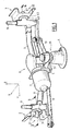
- FIG 1 there is shown a mechanism 1 windscreen wiper for a motor vehicle and three supports rigid 2, 3, 4 fixing, integral with a part of motor vehicle body (not shown). These supports are, for example, made of sheet metal and welded on the box.
- the mechanism 1 will be oriented in an associated X, Y, Z frame to the vehicle on which the mechanism is supposed to be mounted.
- the X axis represents the longitudinal axis of the vehicle forward
- the Y axis is the transverse axis oriented from left to right.
- Positioning and fixing mechanism 1 on the vehicle body are made by means of three pairs 21, 22, 23 complementary fasteners.
- the first pair 21 comprises on the one hand a nipple cylindrical 31, free end of semi-spherical shape, which protrudes from the bar 9 at one end of this last (right end), substantially in the extension of the main direction of the bar.
- the first pair 21 has on the other hand a second element of fastener formed of a plate 33 secured to the support 2, this plate having an oblong hole 35, complementary to the nipple 31.
- the oblong hole 35 extends substantially according to the longitudinal direction X, and opens on the front side of the plate 33, defining a lateral opening introduction of the nipple 31.
- the wafer 33 is formed also with a rim 37 extending over the periphery of the oblong hole 35, so as to constitute a support part plan for the nipple 31.
- the stud 31 When the pin 31 is engaged in the oblong hole 35, as shown in Figure 1, the stud 31 extends along the transverse axis Y, and the two elements of 31, 33 together define a support bearing of the mechanism 1 on the vehicle body, allowing a freedom of rotation of the mechanism around the Y axis, as well as that a sliding along the axis X of the pin 31 with respect to the plate 33.
- the second element of the first pair 21 is provided with a collar 39 secured to the nipple 31 at the base of the latter, and intended to limit the engagement of the pin in the slot 35 along the axis Y.
- the pin 31 and the ring 39 are for example formed of a part fitted on a cylindrical projection 40 of mechanism end 1.
- this piece forming the pin 31 and the collar 39 is an elastomeric sleeve, for example of rubber. This sleeve is intended to deform slightly in compression during his engagement in the 35 oblong hole, and so ensure friction retention of the end corresponding mechanism, in commitment with the support 2.
- the second pair 22 comprises on the one hand a stud 41 similar to the pin 31, substantially of the same axis and oriented opposite way, arranged at the other end of the bar transverse 9 (left end).
- the nipple 41 constitutes the first fastening element of the second pair 22.
- the second pair 22 includes on the other hand a second fastener, in the form of a plate 43 secured to the support 3, provided with a circular hole 45 receiving the stud 41, complementary to the latter.
- the circular hole 45 is substantially of Y axis, so that when the pin 41 is engaged in the circular hole 45, as shown in Figure 1, the second pair fixing element 22 defines a bearing support of a end of the mechanism 1 on the vehicle body, with a degree of freedom in rotation around the transverse axis Y.
- the wafer 43 is formed with a rim 47 extending at the periphery of the hole 45 so as to constitute a peripheral support surface for the nipple 41, larger than that defined by the thickness of the plate 43.
- first fastening element of the second pair 22 is, similar to what has been described for the first pair 21, provided with a collar 49 formed at the base of the pin 41, in order to limit the engagement in the latter in hole 45.
- the pin 41 is formed of a piece with the collar 49, this part being a sleeve fitted on a projection 50 end of the mechanism.
- the sleeve is preferably made of elastomeric material, such as rubber, and designed to provide friction retention when the pin 41 is engaged in the hole 45. This sleeve allows also to get a clearance game, compared to the axis of the hole 45 of the mechanism 1 when the pin 41 is engaged in the hole.
- the links defined by the first 21 and second 22 pairs of fasteners provide mechanism 1 with freedom of rotation and limited freedom of translation by the flanges 39, 49, along the common axis Y of the bearings.
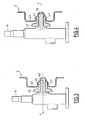
- the third pair of fasteners 23 has a first element 51 integral with the mechanism 1, and a second element 52 ( Figure 2), integral with the support 4.
- the second element 52 is essentially formed of a cylindrical rod 54, which protrudes vertically upward from the support 4, and a ball 56 formed at the free end of the rod.
- the first fastening element 51 comprises a block carrier 61 made of elastomeric material, for example rubber, attached to plate 5 of mechanism 1.
- the block carrier 61 is of outer shape essentially cylindrical, with a peripheral groove 63. To ensure fixing the carrier block 61 on the plate 5, this last includes a circular bore in which is coaxially engaged the carrier block 61, the peripheral edge 65 of this bore being forcibly engaged in the groove device 63.
- the fixing bore of the carrier block 61 can be bi-circular, a first part of larger diameter being planned for engagement axial block 61, and a second part of smaller diameter being provided for blocking by force engagement of block 61.
- the two parts are laterally shifted and communicate through a choked section.
- the carrier block 61 in its part lower, is formed internally with a groove 66, the bottom is turned towards the bore edge of the plate 5, and extends near the latter. So, the throat 66 defines a weakening region of the carrier block 61, planned to allow the latter to break down during a impact on the mechanism (including pedestrian impact), and the separation of mechanism 1 and the part of checkout.
- Element 51 further comprises a rigid bushing 67 coaxially fixed inside the carrier block 61.
- the rigid bushing 67 may consist of plastic material overmolded inside the carrier block 61.
- the element 51 further comprises a ring 69 attached to the upper end of the sleeve 67, closing partially the upper opening of the latter.
- the element 51 has a crew mobile device consisting of a deformable sleeve 71 and a button 73.
- the deformable sleeve 71 comprises, in the example shown, an upper tubular body 75 essentially rigid, and three legs 77 elastically deformable, which project axially downward since the lower edge of the tubular body 75. In its part lower, the tubular body 75 is formed with a peripheral flange 79 forming a shoulder.
- the tubular body 75 has, at its lower end, a complementary 75A footprint of an upper spherical cap of the patella 56.
- the operating knob 73 is attached to the sleeve deformable 71 by press fitting a central portion cylindrical 81 in the tubular body 75.
- the deformable sleeve 71 is mounted within the rigid bushing 67 capped by the ring 69, so as to ability to slide axially inside the sleeve 67.
- the operating knob 73 protrudes upwards from the fixed assembly formed by the rigid bushing 67 and the bushing 69.
- the outside diameter of the tubular body 75 is less than that of the central bore of the ring 69, so that the body 75 can slide freely axially through this central bore.
- the sliding of the sleeve 71 in the sleeve 67 is stopped upwards by the abutment of the flange 79 on the ring 69, at the periphery of the central bore.
- the elastic tabs 77 have an inner profile, that is, turned towards the axis of the sleeve, such that rotation of this profile around the axis of the sleeve generates a surface complementary to that of the patella 56.
- each leg 77 has a curved profile, on the side of the body 75, according to an arc of a circle with the same radius as that of the kneecap 56, and presents on the side of its free end, a part forming a hook 82, radially projecting towards the axis of the sleeve 71.
- the resilient tabs 77 can thus receive between them the ball 56 by complementarity of form and ensure axial retention of the latter. In this position, the upper part of the ball 56 comes into bearing on the footprint 75A of the tubular body 75, which ensures the axial stop towards the top of the ball 56 relative to the sleeve 71, as shown in Figure 5.
- the inner profile of the legs elastics 77 presents successively, since the end lower body 75 towards the free end of the tabs 77, a part in a circular arc 77A complementary to the patella 56, a linear portion 77B parallel to the Z axis corresponding to the hook portion 82, and a portion end linear 77C, defining with the profile of other legs 77 a frustoconical entry, flared towards the outside, of the deformable sleeve 71.
- the sleeve 67 on the side of its lower end, also has an inner section of frustoconical shape 83, defining on the contrary a narrowing at the bottom outlet of the central bore of the socket 67.
- the element 51 is provided with an axial spring 85 threaded on the tubular body 75, spring which bears firstly on the flange 79, and secondly on the ring 69, in periphery of the central bore.
- the spring 85 ensures the reminder of the deformable sleeve 71 in abutment position on the frustoconical section 83.
- the elements 51, 52 operate by elastic interlocking along a vertical engagement axis Z.
- the elastomeric block 61 makes it possible to compensate for a significant misalignment of these elements of fixing 51, 52.
- pairs of fasteners 21, 22 is substantially orthogonal to the engagement direction Z defined by the third pair fasteners 23.
- Figure 9 shows the rest position of the first element 51 of the pair, the first element 51 being waiting for commitment on the second element 52.
- the mobile team formed from deformable sleeve 71 and integral operating knob 73 is in its low abutment position in the socket rigid 67.
- the sleeve 71 is urged in this position by the spring 85, so that the free ends of the tabs 77 are held in support on the section frustoconical 83 of the sleeve 67.
- the pair of fasteners arrives in the locking configuration of the two fasteners 51, 52, as shown in Figure 5.
- the deformable sleeve 71 is in a position in the rigid socket 67 that prevents, within the limit of some threshold effort, the separation two fastening elements 51, 52 by simple pulling.
- the legs 77 deform elastically away from the Z axis. Their deformation is made possible by their passage through the cylindrical section of the central bore of the sleeve 67. In other words, the spacing of the free ends legs 77 is no longer restricted by the section frustoconical 83.
- the operator can then pull the windscreen wiper mechanism upward while maintaining a pull on the button lock 73, against the elastic return of the spring 85, so as to completely disengage the ball 56 from the deformable sleeve 71 and the rigid sleeve 67.
Landscapes
- Engineering & Computer Science (AREA)
- Mechanical Engineering (AREA)
- Connection Of Plates (AREA)
- Snaps, Bayonet Connections, Set Pins, And Snap Rings (AREA)
- Automobile Manufacture Line, Endless Track Vehicle, Trailer (AREA)
- Pivots And Pivotal Connections (AREA)
- Insertion Pins And Rivets (AREA)
- Vehicle Interior And Exterior Ornaments, Soundproofing, And Insulation (AREA)
Applications Claiming Priority (2)
| Application Number | Priority Date | Filing Date | Title |
|---|---|---|---|
| FR0314156A FR2863021B1 (fr) | 2003-12-02 | 2003-12-02 | Dispositif de positionnement et de fixation de deux pieces mecaniques, agencement de vehicule automobile comprenant un tel dispositif, et vehicule comprenant un tel agencement |
| FR0314156 | 2003-12-02 |
Publications (2)
| Publication Number | Publication Date |
|---|---|
| EP1555176A1 true EP1555176A1 (de) | 2005-07-20 |
| EP1555176B1 EP1555176B1 (de) | 2006-11-08 |
Family
ID=34566326
Family Applications (1)
| Application Number | Title | Priority Date | Filing Date |
|---|---|---|---|
| EP04292772A Expired - Lifetime EP1555176B1 (de) | 2003-12-02 | 2004-11-24 | Positionier- und Befestigunseinrichtung für zwei mechanische Teile, Fahrzeuganordnung mit einer solchen Einrichtung und Fahrzeug mit einer solchen Anordnung |
Country Status (5)
| Country | Link |
|---|---|
| EP (1) | EP1555176B1 (de) |
| AT (1) | ATE344748T1 (de) |
| DE (1) | DE602004003122T2 (de) |
| ES (1) | ES2280018T3 (de) |
| FR (1) | FR2863021B1 (de) |
Cited By (2)
| Publication number | Priority date | Publication date | Assignee | Title |
|---|---|---|---|---|
| EP1763460B1 (de) * | 2004-02-17 | 2009-10-28 | Robert Bosch Gmbh | Vorrichtung zur befestigung einer scheibenwishvorrichtung an einem kraftfahrzeug |
| WO2012003913A1 (de) | 2010-07-06 | 2012-01-12 | Bayerische Motoren Werke Aktiengesellschaft | Befestigungsanordnung zum befestigen von kraftfahrzeugbauteilen |
Families Citing this family (6)
| Publication number | Priority date | Publication date | Assignee | Title |
|---|---|---|---|---|
| DE102006061675A1 (de) * | 2006-12-28 | 2008-07-03 | Robert Bosch Gmbh | Scheibenwischvorrichtung |
| DE102007027663B4 (de) | 2007-06-15 | 2017-03-30 | Robert Bosch Gmbh | Antriebsvorrichtung |
| DE102007028383A1 (de) * | 2007-06-20 | 2008-12-24 | Robert Bosch Gmbh | Scheibenwischerantriebsanordnung |
| FR2947020B1 (fr) * | 2009-06-17 | 2011-07-22 | Renault Sas | Dispositif de fixation d'une piece mecanique a un support, notamment d'un moteur d'essuie-vitre arriere a la carrosserie d'un vehicule automobile et agencement de fixation obtenu |
| DE102020213009A1 (de) | 2020-10-15 | 2022-04-21 | Robert Bosch Gesellschaft mit beschränkter Haftung | Wischervorrichtung für ein Fahrzeug, sowie Fahrzeug mit einer solchen Wischervorrichtung |
| EP4733607A1 (de) | 2024-10-23 | 2026-04-29 | Newfrey LLC | Befestigungselement zur befestigung eines ersten karosseriebauteils an einem zweiten karosseriebauteil |
Citations (8)
| Publication number | Priority date | Publication date | Assignee | Title |
|---|---|---|---|---|
| FR2534537A1 (fr) * | 1982-10-19 | 1984-04-20 | Bosch Gmbh Robert | Dispositif d'essuie-glace pour vehicules automobiles |
| EP0359733A2 (de) * | 1988-09-16 | 1990-03-21 | Aktiebolaget Electrolux | Scheibenwischereinheit, vorzugsweise für Fahrzeuge |
| EP0574309A1 (de) * | 1992-06-12 | 1993-12-15 | Valeo Systemes D'essuyage | Wischermodul, insbesondere für die Windschutzscheibe eines Kraftfahrzeugs |
| JPH0776263A (ja) * | 1993-09-08 | 1995-03-20 | Nissan Motor Co Ltd | ボールジョイント部構造 |
| DE4409957A1 (de) * | 1994-03-23 | 1995-09-28 | Teves Gmbh Alfred | Lagervorrichtung für eine Welle oder Achse, insbesondere für eine Scheibenwischeranlage, und Scheibenwischeranlage |
| DE19642672A1 (de) * | 1996-03-26 | 1997-10-02 | Bosch Gmbh Robert | Rohrplatine |
| FR2761318A1 (fr) * | 1997-03-28 | 1998-10-02 | Valeo Systemes Dessuyage | Systeme d'essuyage comportant une traverse qui supporte un ensemble motoreducteur |
| FR2789132A1 (fr) * | 1999-02-03 | 2000-08-04 | Peugeot Citroen Automobiles Sa | Dispositif d'articulation de deux organes mobiles sur un organe de base et dispositif d'entrainement pour essuie-glace muni de ce dispositif d'articulation |
-
2003
- 2003-12-02 FR FR0314156A patent/FR2863021B1/fr not_active Expired - Fee Related
-
2004
- 2004-11-24 AT AT04292772T patent/ATE344748T1/de not_active IP Right Cessation
- 2004-11-24 ES ES04292772T patent/ES2280018T3/es not_active Expired - Lifetime
- 2004-11-24 EP EP04292772A patent/EP1555176B1/de not_active Expired - Lifetime
- 2004-11-24 DE DE602004003122T patent/DE602004003122T2/de not_active Expired - Lifetime
Patent Citations (8)
| Publication number | Priority date | Publication date | Assignee | Title |
|---|---|---|---|---|
| FR2534537A1 (fr) * | 1982-10-19 | 1984-04-20 | Bosch Gmbh Robert | Dispositif d'essuie-glace pour vehicules automobiles |
| EP0359733A2 (de) * | 1988-09-16 | 1990-03-21 | Aktiebolaget Electrolux | Scheibenwischereinheit, vorzugsweise für Fahrzeuge |
| EP0574309A1 (de) * | 1992-06-12 | 1993-12-15 | Valeo Systemes D'essuyage | Wischermodul, insbesondere für die Windschutzscheibe eines Kraftfahrzeugs |
| JPH0776263A (ja) * | 1993-09-08 | 1995-03-20 | Nissan Motor Co Ltd | ボールジョイント部構造 |
| DE4409957A1 (de) * | 1994-03-23 | 1995-09-28 | Teves Gmbh Alfred | Lagervorrichtung für eine Welle oder Achse, insbesondere für eine Scheibenwischeranlage, und Scheibenwischeranlage |
| DE19642672A1 (de) * | 1996-03-26 | 1997-10-02 | Bosch Gmbh Robert | Rohrplatine |
| FR2761318A1 (fr) * | 1997-03-28 | 1998-10-02 | Valeo Systemes Dessuyage | Systeme d'essuyage comportant une traverse qui supporte un ensemble motoreducteur |
| FR2789132A1 (fr) * | 1999-02-03 | 2000-08-04 | Peugeot Citroen Automobiles Sa | Dispositif d'articulation de deux organes mobiles sur un organe de base et dispositif d'entrainement pour essuie-glace muni de ce dispositif d'articulation |
Non-Patent Citations (1)
| Title |
|---|
| PATENT ABSTRACTS OF JAPAN vol. 1995, no. 06 31 July 1995 (1995-07-31) * |
Cited By (6)
| Publication number | Priority date | Publication date | Assignee | Title |
|---|---|---|---|---|
| EP1763460B1 (de) * | 2004-02-17 | 2009-10-28 | Robert Bosch Gmbh | Vorrichtung zur befestigung einer scheibenwishvorrichtung an einem kraftfahrzeug |
| WO2012003913A1 (de) | 2010-07-06 | 2012-01-12 | Bayerische Motoren Werke Aktiengesellschaft | Befestigungsanordnung zum befestigen von kraftfahrzeugbauteilen |
| DE102010030964A1 (de) | 2010-07-06 | 2012-01-12 | Bayerische Motoren Werke Aktiengesellschaft | Befestigungsanordnung zum Befestigen von Kraftfahrzeugbauteilen |
| CN102958762A (zh) * | 2010-07-06 | 2013-03-06 | 宝马股份公司 | 用于固定机动车构件的固定装置 |
| CN102958762B (zh) * | 2010-07-06 | 2015-07-22 | 宝马股份公司 | 用于固定机动车构件的固定装置 |
| US9097272B2 (en) | 2010-07-06 | 2015-08-04 | Bayerische Motoren Werke Aktiengesellschaft | Fixing arrangement for fixing motor vehicle components |
Also Published As
| Publication number | Publication date |
|---|---|
| DE602004003122D1 (de) | 2006-12-21 |
| FR2863021A1 (fr) | 2005-06-03 |
| ATE344748T1 (de) | 2006-11-15 |
| DE602004003122T2 (de) | 2007-03-08 |
| ES2280018T3 (es) | 2007-09-01 |
| FR2863021B1 (fr) | 2006-04-14 |
| EP1555176B1 (de) | 2006-11-08 |
Similar Documents
| Publication | Publication Date | Title |
|---|---|---|
| FR2955062A1 (fr) | Systeme d'articulation et siege de vehicule comportant un tel systeme d'articulation. | |
| FR2820375A1 (fr) | Dispositif de fixation pour accoudoir amovible et dispositif d'assise comportant un tel dispositif de fixation | |
| FR2953489A1 (fr) | Systeme de fixation d'un siege notamment d'aeronef et siege comportant au moins un tel systeme. | |
| EP0750087B1 (de) | Verbesserte Verriegelung, insbesondere zum Befestigen eines Autositzes am Kraftfahrzeugboden | |
| EP1555176B1 (de) | Positionier- und Befestigunseinrichtung für zwei mechanische Teile, Fahrzeuganordnung mit einer solchen Einrichtung und Fahrzeug mit einer solchen Anordnung | |
| FR3043027A1 (fr) | Siege de vehicule | |
| EP0919679A1 (de) | Schnappverriegelungseinrichtung, insbesondere für die Befestigung eines Fahrzeugsitzes am Fahrzeugboden | |
| FR2656261A1 (fr) | Ensemble formant siege de vehicule. | |
| EP1552994B1 (de) | Lösbare Vorrichtung zur Ausrichtung und Befestigung von zwei mechanischen Teilen, Fahrzeuganordnung mit einer solchen Vorrichtung und derartiges Fahrzeug mit einer solchen Anordnung | |
| FR2977202A1 (fr) | Siege pour un vehicule | |
| EP1136313B1 (de) | Verstelleinheit für Kopfstütze | |
| FR2862926A1 (fr) | Dispositif et procede de fixation d'un mecanisme d'essuie-vitre sur une partie de caisse de vehicule, et vehicule equipe d'un tel dispositif | |
| FR2862927A1 (fr) | Dispositif et procede de positionnement et de fixation d'un mecanisme d'essuie-vitre sur une partie de caisse de vehicule automobile equipe d'un tel dispositif | |
| EP3436314A1 (de) | Verstellbare sitzstruktur eines fahrzeugsitzes mit einem sitzgurtschlossteil | |
| EP1721795B1 (de) | Vorrichtung sowie Verfahren zur Befestigung eines Scheibenwischermechanismus auf einem Fahrzeugkarosserieteil, und Kraftfahrzeug mit einer solchen Vorrichtung | |
| FR2778876A1 (fr) | Dispositif de verrouillage d'un dossier inclinable d'une banquette dans un vehicule | |
| FR2882022A1 (fr) | Dispositif de fixation automatique d'une planche de bord sur une caisse de vehicule automobile | |
| FR2756787A1 (fr) | Dispositif de montage d'un accoudoir sur une colonne | |
| FR2885577A1 (fr) | Dispositif perfectionne de fixation d'un mecanisme d'essuie-vitre sur une partie de caisse de vehicule, et vehicule automobile equipe d'un tel dispositif | |
| FR3122127A1 (fr) | Dispositif de blocage en rotation de l’assise d’un siège de véhicule | |
| FR2692946A1 (fr) | Dispositif de fixation. | |
| FR2794821A1 (fr) | Ensemble de verrouillage destine notamment a l'accrochage d'un siege de vehicule automobile sur un plancher de ce vehicule | |
| FR2736958A1 (fr) | Gache pour serrure de coffre d'un vehicule automobile | |
| FR2706409A1 (fr) | Dispositif d'accrochage réversible d'un siège sur un plancher de véhicule automobile. | |
| FR2720126A1 (fr) | Dispositif d'assemblage d'au moins deux éléments par exemple de carrosserie automobile. |
Legal Events
| Date | Code | Title | Description |
|---|---|---|---|
| PUAI | Public reference made under article 153(3) epc to a published international application that has entered the european phase |
Free format text: ORIGINAL CODE: 0009012 |
|
| AK | Designated contracting states |
Kind code of ref document: A1 Designated state(s): AT BE BG CH CY CZ DE DK EE ES FI FR GB GR HU IE IS IT LI LU MC NL PL PT RO SE SI SK TR |
|
| AX | Request for extension of the european patent |
Extension state: AL HR LT LV MK YU |
|
| 17P | Request for examination filed |
Effective date: 20050728 |
|
| AKX | Designation fees paid |
Designated state(s): AT BE BG CH CY CZ DE DK EE ES FI FR GB GR HU IE IS IT LI LU MC NL PL PT RO SE SI SK TR |
|
| GRAP | Despatch of communication of intention to grant a patent |
Free format text: ORIGINAL CODE: EPIDOSNIGR1 |
|
| GRAS | Grant fee paid |
Free format text: ORIGINAL CODE: EPIDOSNIGR3 |
|
| GRAA | (expected) grant |
Free format text: ORIGINAL CODE: 0009210 |
|
| AK | Designated contracting states |
Kind code of ref document: B1 Designated state(s): AT BE BG CH CY CZ DE DK EE ES FI FR GB GR HU IE IS IT LI LU MC NL PL PT RO SE SI SK TR |
|
| PG25 | Lapsed in a contracting state [announced via postgrant information from national office to epo] |
Ref country code: NL Free format text: LAPSE BECAUSE OF FAILURE TO SUBMIT A TRANSLATION OF THE DESCRIPTION OR TO PAY THE FEE WITHIN THE PRESCRIBED TIME-LIMIT Effective date: 20061108 Ref country code: CZ Free format text: LAPSE BECAUSE OF FAILURE TO SUBMIT A TRANSLATION OF THE DESCRIPTION OR TO PAY THE FEE WITHIN THE PRESCRIBED TIME-LIMIT Effective date: 20061108 Ref country code: IT Free format text: LAPSE BECAUSE OF FAILURE TO SUBMIT A TRANSLATION OF THE DESCRIPTION OR TO PAY THE FEE WITHIN THE PRESCRIBED TIME-LIMIT;WARNING: LAPSES OF ITALIAN PATENTS WITH EFFECTIVE DATE BEFORE 2007 MAY HAVE OCCURRED AT ANY TIME BEFORE 2007. THE CORRECT EFFECTIVE DATE MAY BE DIFFERENT FROM THE ONE RECORDED. Effective date: 20061108 Ref country code: RO Free format text: LAPSE BECAUSE OF FAILURE TO SUBMIT A TRANSLATION OF THE DESCRIPTION OR TO PAY THE FEE WITHIN THE PRESCRIBED TIME-LIMIT Effective date: 20061108 Ref country code: SK Free format text: LAPSE BECAUSE OF FAILURE TO SUBMIT A TRANSLATION OF THE DESCRIPTION OR TO PAY THE FEE WITHIN THE PRESCRIBED TIME-LIMIT Effective date: 20061108 Ref country code: FI Free format text: LAPSE BECAUSE OF FAILURE TO SUBMIT A TRANSLATION OF THE DESCRIPTION OR TO PAY THE FEE WITHIN THE PRESCRIBED TIME-LIMIT Effective date: 20061108 Ref country code: PL Free format text: LAPSE BECAUSE OF FAILURE TO SUBMIT A TRANSLATION OF THE DESCRIPTION OR TO PAY THE FEE WITHIN THE PRESCRIBED TIME-LIMIT Effective date: 20061108 Ref country code: AT Free format text: LAPSE BECAUSE OF FAILURE TO SUBMIT A TRANSLATION OF THE DESCRIPTION OR TO PAY THE FEE WITHIN THE PRESCRIBED TIME-LIMIT Effective date: 20061108 Ref country code: IE Free format text: LAPSE BECAUSE OF FAILURE TO SUBMIT A TRANSLATION OF THE DESCRIPTION OR TO PAY THE FEE WITHIN THE PRESCRIBED TIME-LIMIT Effective date: 20061108 Ref country code: SI Free format text: LAPSE BECAUSE OF FAILURE TO SUBMIT A TRANSLATION OF THE DESCRIPTION OR TO PAY THE FEE WITHIN THE PRESCRIBED TIME-LIMIT Effective date: 20061108 |
|
| REG | Reference to a national code |
Ref country code: GB Ref legal event code: FG4D Free format text: NOT ENGLISH |
|
| PG25 | Lapsed in a contracting state [announced via postgrant information from national office to epo] |
Ref country code: MC Free format text: LAPSE BECAUSE OF NON-PAYMENT OF DUE FEES Effective date: 20061130 Ref country code: BE Free format text: LAPSE BECAUSE OF NON-PAYMENT OF DUE FEES Effective date: 20061130 |
|
| REG | Reference to a national code |
Ref country code: CH Ref legal event code: EP |
|
| REG | Reference to a national code |
Ref country code: IE Ref legal event code: FG4D Free format text: LANGUAGE OF EP DOCUMENT: FRENCH |
|
| REF | Corresponds to: |
Ref document number: 602004003122 Country of ref document: DE Date of ref document: 20061221 Kind code of ref document: P |
|
| PG25 | Lapsed in a contracting state [announced via postgrant information from national office to epo] |
Ref country code: DK Free format text: LAPSE BECAUSE OF FAILURE TO SUBMIT A TRANSLATION OF THE DESCRIPTION OR TO PAY THE FEE WITHIN THE PRESCRIBED TIME-LIMIT Effective date: 20070208 Ref country code: SE Free format text: LAPSE BECAUSE OF FAILURE TO SUBMIT A TRANSLATION OF THE DESCRIPTION OR TO PAY THE FEE WITHIN THE PRESCRIBED TIME-LIMIT Effective date: 20070208 Ref country code: BG Free format text: LAPSE BECAUSE OF FAILURE TO SUBMIT A TRANSLATION OF THE DESCRIPTION OR TO PAY THE FEE WITHIN THE PRESCRIBED TIME-LIMIT Effective date: 20070208 |
|
| GBT | Gb: translation of ep patent filed (gb section 77(6)(a)/1977) |
Effective date: 20070125 |
|
| PG25 | Lapsed in a contracting state [announced via postgrant information from national office to epo] |
Ref country code: IS Free format text: LAPSE BECAUSE OF FAILURE TO SUBMIT A TRANSLATION OF THE DESCRIPTION OR TO PAY THE FEE WITHIN THE PRESCRIBED TIME-LIMIT Effective date: 20070308 |
|
| PG25 | Lapsed in a contracting state [announced via postgrant information from national office to epo] |
Ref country code: PT Free format text: LAPSE BECAUSE OF FAILURE TO SUBMIT A TRANSLATION OF THE DESCRIPTION OR TO PAY THE FEE WITHIN THE PRESCRIBED TIME-LIMIT Effective date: 20070409 |
|
| NLV1 | Nl: lapsed or annulled due to failure to fulfill the requirements of art. 29p and 29m of the patents act | ||
| REG | Reference to a national code |
Ref country code: IE Ref legal event code: FD4D |
|
| REG | Reference to a national code |
Ref country code: ES Ref legal event code: FG2A Ref document number: 2280018 Country of ref document: ES Kind code of ref document: T3 |
|
| PLBE | No opposition filed within time limit |
Free format text: ORIGINAL CODE: 0009261 |
|
| STAA | Information on the status of an ep patent application or granted ep patent |
Free format text: STATUS: NO OPPOSITION FILED WITHIN TIME LIMIT |
|
| 26N | No opposition filed |
Effective date: 20070809 |
|
| BERE | Be: lapsed |
Owner name: PEUGEOT CITROEN AUTOMOBILES S.A. Effective date: 20061130 |
|
| REG | Reference to a national code |
Ref country code: GB Ref legal event code: 746 Effective date: 20080329 |
|
| PG25 | Lapsed in a contracting state [announced via postgrant information from national office to epo] |
Ref country code: GR Free format text: LAPSE BECAUSE OF FAILURE TO SUBMIT A TRANSLATION OF THE DESCRIPTION OR TO PAY THE FEE WITHIN THE PRESCRIBED TIME-LIMIT Effective date: 20070209 |
|
| PG25 | Lapsed in a contracting state [announced via postgrant information from national office to epo] |
Ref country code: EE Free format text: LAPSE BECAUSE OF FAILURE TO SUBMIT A TRANSLATION OF THE DESCRIPTION OR TO PAY THE FEE WITHIN THE PRESCRIBED TIME-LIMIT Effective date: 20061108 |
|
| PG25 | Lapsed in a contracting state [announced via postgrant information from national office to epo] |
Ref country code: HU Free format text: LAPSE BECAUSE OF FAILURE TO SUBMIT A TRANSLATION OF THE DESCRIPTION OR TO PAY THE FEE WITHIN THE PRESCRIBED TIME-LIMIT Effective date: 20070509 Ref country code: LU Free format text: LAPSE BECAUSE OF NON-PAYMENT OF DUE FEES Effective date: 20061124 Ref country code: TR Free format text: LAPSE BECAUSE OF FAILURE TO SUBMIT A TRANSLATION OF THE DESCRIPTION OR TO PAY THE FEE WITHIN THE PRESCRIBED TIME-LIMIT Effective date: 20061108 |
|
| PG25 | Lapsed in a contracting state [announced via postgrant information from national office to epo] |
Ref country code: CY Free format text: LAPSE BECAUSE OF FAILURE TO SUBMIT A TRANSLATION OF THE DESCRIPTION OR TO PAY THE FEE WITHIN THE PRESCRIBED TIME-LIMIT Effective date: 20061108 |
|
| REG | Reference to a national code |
Ref country code: CH Ref legal event code: PL |
|
| PG25 | Lapsed in a contracting state [announced via postgrant information from national office to epo] |
Ref country code: LI Free format text: LAPSE BECAUSE OF NON-PAYMENT OF DUE FEES Effective date: 20081130 Ref country code: CH Free format text: LAPSE BECAUSE OF NON-PAYMENT OF DUE FEES Effective date: 20081130 |
|
| PGFP | Annual fee paid to national office [announced via postgrant information from national office to epo] |
Ref country code: ES Payment date: 20091106 Year of fee payment: 6 |
|
| PGFP | Annual fee paid to national office [announced via postgrant information from national office to epo] |
Ref country code: IT Payment date: 20091031 Year of fee payment: 6 |
|
| PG25 | Lapsed in a contracting state [announced via postgrant information from national office to epo] |
Ref country code: IT Free format text: LAPSE BECAUSE OF NON-PAYMENT OF DUE FEES Effective date: 20101124 |
|
| REG | Reference to a national code |
Ref country code: ES Ref legal event code: FD2A Effective date: 20120110 |
|
| PG25 | Lapsed in a contracting state [announced via postgrant information from national office to epo] |
Ref country code: ES Free format text: LAPSE BECAUSE OF NON-PAYMENT OF DUE FEES Effective date: 20101125 |
|
| PGFP | Annual fee paid to national office [announced via postgrant information from national office to epo] |
Ref country code: GB Payment date: 20121025 Year of fee payment: 9 |
|
| GBPC | Gb: european patent ceased through non-payment of renewal fee |
Effective date: 20131124 |
|
| PG25 | Lapsed in a contracting state [announced via postgrant information from national office to epo] |
Ref country code: GB Free format text: LAPSE BECAUSE OF NON-PAYMENT OF DUE FEES Effective date: 20131124 |
|
| REG | Reference to a national code |
Ref country code: FR Ref legal event code: PLFP Year of fee payment: 12 |
|
| PGFP | Annual fee paid to national office [announced via postgrant information from national office to epo] |
Ref country code: DE Payment date: 20151022 Year of fee payment: 12 |
|
| REG | Reference to a national code |
Ref country code: FR Ref legal event code: PLFP Year of fee payment: 13 |
|
| PGFP | Annual fee paid to national office [announced via postgrant information from national office to epo] |
Ref country code: FR Payment date: 20161024 Year of fee payment: 13 |
|
| REG | Reference to a national code |
Ref country code: DE Ref legal event code: R119 Ref document number: 602004003122 Country of ref document: DE |
|
| PG25 | Lapsed in a contracting state [announced via postgrant information from national office to epo] |
Ref country code: DE Free format text: LAPSE BECAUSE OF NON-PAYMENT OF DUE FEES Effective date: 20170601 |
|
| REG | Reference to a national code |
Ref country code: FR Ref legal event code: CA Effective date: 20180312 Ref country code: FR Ref legal event code: CD Owner name: PEUGEOT CITROEN AUTOMOBILES SA, FR Effective date: 20180312 |
|
| REG | Reference to a national code |
Ref country code: FR Ref legal event code: ST Effective date: 20180731 |
|
| PG25 | Lapsed in a contracting state [announced via postgrant information from national office to epo] |
Ref country code: FR Free format text: LAPSE BECAUSE OF NON-PAYMENT OF DUE FEES Effective date: 20171130 |