EP0233172B1 - Platte aus rostfreiem Stahl und Walzvorrichtung zur Herstellung von Platten - Google Patents
Platte aus rostfreiem Stahl und Walzvorrichtung zur Herstellung von Platten Download PDFInfo
- Publication number
- EP0233172B1 EP0233172B1 EP19870890014 EP87890014A EP0233172B1 EP 0233172 B1 EP0233172 B1 EP 0233172B1 EP 19870890014 EP19870890014 EP 19870890014 EP 87890014 A EP87890014 A EP 87890014A EP 0233172 B1 EP0233172 B1 EP 0233172B1
- Authority
- EP
- European Patent Office
- Prior art keywords
- rollers
- deforming
- rolling device
- deformation
- profile
- Prior art date
- Legal status (The legal status is an assumption and is not a legal conclusion. Google has not performed a legal analysis and makes no representation as to the accuracy of the status listed.)
- Expired - Lifetime
Links
Images


Classifications
-
- E—FIXED CONSTRUCTIONS
- E04—BUILDING
- E04B—GENERAL BUILDING CONSTRUCTIONS; WALLS, e.g. PARTITIONS; ROOFS; FLOORS; CEILINGS; INSULATION OR OTHER PROTECTION OF BUILDINGS
- E04B1/00—Constructions in general; Structures which are not restricted either to walls, e.g. partitions, or floors or ceilings or roofs
- E04B1/62—Insulation or other protection; Elements or use of specified material therefor
- E04B1/64—Insulation or other protection; Elements or use of specified material therefor for making damp-proof; Protection against corrosion
- E04B1/644—Damp-proof courses
-
- E—FIXED CONSTRUCTIONS
- E04—BUILDING
- E04C—STRUCTURAL ELEMENTS; BUILDING MATERIALS
- E04C2/00—Building elements of relatively thin form for the construction of parts of buildings, e.g. sheet materials, slabs, or panels
- E04C2/30—Building elements of relatively thin form for the construction of parts of buildings, e.g. sheet materials, slabs, or panels characterised by the shape or structure
- E04C2/32—Building elements of relatively thin form for the construction of parts of buildings, e.g. sheet materials, slabs, or panels characterised by the shape or structure formed of corrugated or otherwise indented sheet-like material; composed of such layers with or without layers of flat sheet-like material
- E04C2/322—Building elements of relatively thin form for the construction of parts of buildings, e.g. sheet materials, slabs, or panels characterised by the shape or structure formed of corrugated or otherwise indented sheet-like material; composed of such layers with or without layers of flat sheet-like material with parallel corrugations
Definitions
- the invention relates to a rolling device for the production of stainless steel plates for drying wet masonry, which are driven into the masonry and are corrugated to increase their rigidity, the waves running with their longitudinal axis in the driving direction, with two deformation rollers have a gear-shaped profile in cross-section which forms deformation ribs which run in the axial direction and which mesh with one another in the manner of gearwheels, the axial distance between the two deformation rollers being greater than the sum of the radii of the pitch circles of the toothed rollers.
- the invention also relates to a plate produced with this rolling device.
- the corrugation of the insulating plates increases their rigidity. In the known wave-shaped insulating plates, it can still happen that the plates unintentionally bulge and deform when driven into the masonry, whereupon they can jam in the mortar joint between the guides or against each other.
- the boards can be made of harder and thicker material according to general knowledge. However, this considerably complicates the wave-shaped profiling and also the breaking of the plates.
- the simplest way to produce such corrugated plates is by rolling or pressing, with them being deformed over their entire width simultaneously between profiled pressing tools or being passed through profile rollers in the longitudinal direction of the shafts.
- this deformation is only possible when using plates made of relatively soft, easily deformable steel, because stretching of the material occurs here, which is due to the profiling process and is therefore unavoidable.
- hard material that has a ferritic structure and is not stretchable cracks occur that make the boards unusable or at least cause disadvantageous deformations when driving the boards into the masonry.
- DE-OS 25 05 199 describes a method for producing ventilation ducts, pipe claddings and the like.
- the so-called cross-profiling is used to produce corrugated channel walls.
- Deformation rollers are used, which are arranged at a certain distance from one another and interlock with deformation ribs running in the axial direction.
- a flat sheet metal sheet is passed through these toothed rollers, which is deformed into a corrugated profile with a trapezoidal profile cross section and then cut into the individual components with the aid of a cross cutting device.
- This profiling process is basically also possible with hard material because the sheet metal plates are only bent when they are deformed, but not stretched over the entire cross section. To achieve this, however, certain design features of the rolling device are required, and particular care must also be taken to ensure that the finished corrugated plates have a profile cross section which makes them suitable for their particular purpose.
- the invention has for its object to provide an improved rolling device with which it is possible to produce corrugated plates for draining damp masonry made of stainless steel so that they have an advantageous profile for driving into the masonry despite the use of hard material and do not deform during driving, in particular also have no cracks due to the profiling which could endanger the moisture insulation.
- the rolling device according to the invention is characterized in that the interlocking deformation ribs are formed on their flanks as an involute profile, to which the profile of the tip circle and the base circle connects, that the pressure angle of the deformation ribs in the area of the pitch circle is at least 30 ° and that The tooth height of the deformation ribs is at least 15% of the radius of the pitch circle.
- This relatively simple rolling device enables the production of the described plates with the advantageous cross-sectional profile, which can consist of hard steel with a ferritic structure, without cracks or other damage occurring during rolling.
- the formation of the deformation rollers according to the invention ensures that only one deformation rib of one deformation roller is in engagement with one deformation rib of the other deformation roller, thereby avoiding stretching of the material over the entire deformation cross section of the deformed plates and the resulting cracks.
- the possible diameter of the deformation rollers is limited.
- the forming rollers which have to be long enough so that long plates, e.g. with a length of one meter and more, can be profiled, therefore have a limited bending stiffness.
- the deformation rollers held at their ends in bearings are provided with support rollers which act on the deformation rollers at diametrically opposite locations on the deformation rollers in the region between the bearings. It is then also possible to process relatively thick sheets without difficulty.
- the support rollers expediently have a tooth profile with the same tip circles and root circles as the deformation rollers and are in engagement with them. It is a further advantage if the distance between the support rollers and the associated deformation rollers is adjustable. The appropriate contact pressure can then always be set depending on the thickness and rigidity of the processed sheet.
- the distance between the deformation rollers, including any support rollers, can also be adjustable, for example by means of a wedge or vertical spindle bearing adjustment. This measure also serves to adapt the rolling device to the thickness of the sheets used and also to change the height of the corrugated profiles.
- the support rollers are expediently provided in pairs, with a plurality of support roller pairs being arranged alongside one another along the deformation rollers and being adjustable separately from one another. This further increases and improves the possibility of adapting the rolling device to the respective operating conditions.
- the deformation rollers for synchronizing their rotational movement are provided with gears which are rotatably mounted on them and which mesh with one another.
- the deformation rollers themselves and their deformation ribs are thereby relieved of influences and forces which are necessary for synchronization, thereby precluding an adverse change in the wave profile of the plates due to such forces. It is advisable to provide the deformation rollers with their own drive motors with the interposition of elastic couplings.
- a further advantageous embodiment of the rolling device according to the invention is that straightening rollers through which the plates are guided are arranged on the inlet side and / or on the outlet side of the forming rollers. These straightening rollers not only effect the correct feeding of the plates to be profiled into the rolling device, but in particular they ensure that the finished corrugated plates just leave the rolling device. This eliminates the need to straighten the plates afterwards.
- the straightening rollers with rubber or plastic coated cylindrical rollers are advantageous. They can be arranged so as to be adjustable transversely to the direction in which the plates pass through the shaping rollers, as a result of which their position and their mutual spacing can be adapted to the respective properties of the plates and the operating conditions.
- the straightening rolls are expediently empirical adjusted each time until the corrugated plates produced have a sufficiently precise flat shape.
- a preferred embodiment of the rolling device according to the invention consists in that the deformation rollers are each rotatably mounted in a box-shaped housing, the housings are arranged one above the other in a frame so as to be adjustable relative to one another and have guide shafts provided one behind the other in the longitudinal direction of the deformation rollers, into which the support rollers are slidably inserted and in which they are supported by a set screw. It is a simple and robust rolling device, which nevertheless enables precise adjustment.
- the straightening rollers are arranged on the box-shaped housings and are preferably supported with the aid of adjusting spindles, so that they can also be adjusted in a simple manner.
- a plate made of stainless steel can also be produced, in which, according to the invention, the wave profiles adjoining one another via turning points are circular. At the turning points, two circular sections with opposite curvatures adjoin each other, so that there are practically no flat patches in the area of the turning points.
- a plate profiled in this way does not have the greatest possible stiffness and is in particular less stiff than a comparable plate with a rectangular or trapezoidal wave profile.
- FIG. 1 shows a perspective view of a plate produced with the rolling device according to the invention
- FIG. 2 shows the enlarged wave profile
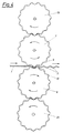
- FIG. 3 shows a detail of the rolling device for producing the corrugated plate
- FIG. 4 shows the entire rolling device in a schematic representation
- 5 shows a side view of the rolling device, partly in an axial central section
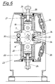
- FIG. 6 shows a cross section through the rolling device along the line VI-VI in FIG. 5.
- the plate 1 shown in Fig. 1 is made of stainless steel and is corrugated to increase its rigidity.
- the waves denoted by 2 in FIG. 1 run parallel to one another.
- the entire (cross-sectional profile 3 of a plate 1 is composed of a plurality of wave profiles 4, which adjoin one another to form wave crests and wave troughs.
- the cross-sectional profile 3 is curved in its entire course, the adjacent wave profiles 4 only via turning points 2, the wave profiles 4 are circular in shape in the exemplary embodiment according to Fig. 2.
- the straight line 6 shown in dash-dotted lines passes through the apexes of a wave crest and the adjacent wave trough as well as through the intermediate turning point 5, the curved course of the cross-sectional profile 3. It is also possible within the scope of the invention to deviate from the circular wave profile, which is also curved differently can be. It is only essential that flat surfaces are avoided in the course of the cross-sectional profile, because flat areas would favor a local deformation of the plate.
- the corrugated plates 1 must be made of hard, stainless steel so that they withstand the mechanical stresses acting on them and do not weather in the masonry itself.
- the materials that meet these requirements can be difficult to deform, especially because they are not stretchable.
- sheet metal panels made of such material are stretched, cracks and sores occur, which, when the panels are driven into the masonry, impair the bending stiffness and the tightness is no longer guaranteed after driving in.
- the rolling device shown schematically in Fig. 3 enables the production of corrugated sheet metal plates made of hard material without this being stretched over the entire deformation cross section.
- the rolling device according to FIG. 3 consists of two deformation rollers 7 and 8, which in cross section have a gear-shaped profile with deformation ribs 9 and 10.
- the two deformation rollers 7, 8 are rotatably arranged one above the other with parallel axes, their deformation ribs 9, 10 meshing like a gear.
- the center distance of the two deformation rollers 7, 8 is greater than the sum of the radii of the rolling circles 11 and 12 of the toothing of the rollers 7, 8, shown in dash-dot lines in FIG. 3. This creates a space between the interlocking deformation ribs 9, 10, between the successive ones Plates 1 are inserted to be provided with shafts 2.
- the interlocking deformation ribs 9, 10 are formed on their flanks 13 and 14 with an involute profile, to which the profile of the tip circle 15 and the root circle 16 adjoins.
- the deformation rollers 7, 8 are designed and arranged such that only one deformation rib 9 of the one deformation roller 7 engages with the deformation ribs 10 of the other deformation roller 8 stands.
- the deformation rollers 7, 8 are designed with a relatively small diameter compared to the tooth height 17 of the two deformation rollers 7, 8.
- the tooth height 17 is at least 15% of the radius of the pitch circle 11, 12 of the associated deformation roller 7.8.
- the plate 1 is inserted in the still flat state in FIG. 3 from the left between the two deformation rollers 7, 8, which are driven at the same speed and in opposite directions.
- the plate 1 is deformed and provided with the shafts 2 between the deformation ribs 9, 10 of the deformation rollers 7, 8.
- the plate 1 can slide in the direction of its plane, so that only its width is reduced.
- Fig. 4 shows schematically the entire Walzvorrichtnng with the deformation rollers 7, 8, the deformation ribs 9, 10 and with the sheet metal plate 1, which is provided with the shafts 2 when passing through the device in the direction of the arrows.
- the shaping rollers 7, 8 must, however, have a relatively small diameter in order to be able to deform the plates 1 without stretching.
- the relatively thin deformation rollers 7, 8 can therefore bend, in particular with a greater length, which results in irregular wave heights over their length and the plates are given a convex shape.
- FIG. 1 shows schematically the entire Walzvorrichtnng with the deformation rollers 7, 8, the deformation ribs 9, 10 and with the sheet metal plate 1, which is provided with the shafts 2 when passing through the device in the direction of the arrows.
- the two deformation rollers 7, 8 with support rollers 19 are therefore and 20, each of which act on the deformation point at diametrically opposite positions on the deformation rollers 7, 8 on the latter.
- the support rollers 19, 20 have the same gear profile as the deformation rollers 7, 8 and are in engagement with them, the toothings rolling directly onto one another.
- the distance between the support rollers is 19, 20 adjustable to the associated deformation rollers 7,8.
- the distance between the two deformation rollers 7 and 8 itself is expediently designed to be adjustable so that it can be adapted to the thickness of the plates 1 to be deformed and the height of the shafts 2 produced can be selected.
- the bearings of the deformation rollers 7, 8 can be used for this purpose be provided with wedge or spindle bearing adjustments not shown in the drawing.
- the deformation rollers 7 and 8 are each supported in a box-shaped housing 21 and 22, the two housings 21, 22 being arranged one above the other in a frame 23.
- the housings 21 and 22 have guide shafts 24 which are provided one behind the other above or below the deformation rollers 7, 8 in the longitudinal direction thereof and are intended for receiving the support rollers 19, 20.
- a support roller 19 is inserted in the middle guide shaft 24 above the deformation roller 7 and can be displaced with the aid of an adjusting screw 25 against the associated deformation roller 7.
- Such a deformation roller 19 together with the adjusting screw 25 could be inserted in all six guide shafts 24 shown in FIG. 5.
- the deformation rollers 7 and 8 are provided for synchronizing their rotational movement with gears 26 and 27 attached to them, which are in engagement with one another, as can be seen from FIG. 5.
- the deformation rollers 7, 8 are also driven in this exemplary embodiment by means of their own drive motors 28, 29.
- the on the frame 23 are anchored.
- Elastic couplings 30 and 31 are switched on in the drive connection.
- straightening rollers 32 are arranged on the inlet side of the deformation rollers 7,8 shown there on the left and straightening rollers 33 are arranged on the outlet side.
- the straightening rollers 32, 33 advantageously consist of cylindrical rollers coated with rubber or plastic and are adjustable transversely to the direction of travel of the plates, so that their distance can be matched to the thickness of the plates.
- the straightening rollers 33 are, as can be seen from FIG. 6, mounted on pivoting levers 34 and supported by means of adjusting spindles 35, so that they can be easily adjusted.
- the rolling device shown and described is relatively simple in construction and nevertheless enables the advantageous production of corrugated plates made of hard stainless steel without the plate material being stretched during the deformation.
Landscapes
- Architecture (AREA)
- Engineering & Computer Science (AREA)
- Civil Engineering (AREA)
- Structural Engineering (AREA)
- Physics & Mathematics (AREA)
- Electromagnetism (AREA)
- Shaping Of Tube Ends By Bending Or Straightening (AREA)
- Bending Of Plates, Rods, And Pipes (AREA)
- Metal Rolling (AREA)
- Press Drives And Press Lines (AREA)
- Lining And Supports For Tunnels (AREA)
- Moulds, Cores, Or Mandrels (AREA)
- Rolling Contact Bearings (AREA)
- Gears, Cams (AREA)
- Shaping Metal By Deep-Drawing, Or The Like (AREA)
- Devices For Post-Treatments, Processing, Supply, Discharge, And Other Processes (AREA)
Applications Claiming Priority (2)
| Application Number | Priority Date | Filing Date | Title |
|---|---|---|---|
| AT249/86 | 1986-02-03 | ||
| AT24986A AT395548B (de) | 1986-02-03 | 1986-02-03 | Walzvorrichtung zur herstellung von gewellten platten |
Publications (3)
| Publication Number | Publication Date |
|---|---|
| EP0233172A2 EP0233172A2 (de) | 1987-08-19 |
| EP0233172A3 EP0233172A3 (en) | 1989-12-13 |
| EP0233172B1 true EP0233172B1 (de) | 1992-04-15 |
Family
ID=3485518
Family Applications (1)
| Application Number | Title | Priority Date | Filing Date |
|---|---|---|---|
| EP19870890014 Expired - Lifetime EP0233172B1 (de) | 1986-02-03 | 1987-01-26 | Platte aus rostfreiem Stahl und Walzvorrichtung zur Herstellung von Platten |
Country Status (8)
| Country | Link |
|---|---|
| EP (1) | EP0233172B1 (da) |
| AT (1) | AT395548B (da) |
| CZ (1) | CZ278264B6 (da) |
| DE (4) | DE8618951U1 (da) |
| DK (1) | DK167777B1 (da) |
| ES (1) | ES2030445T3 (da) |
| HU (1) | HU199320B (da) |
| YU (1) | YU45816B (da) |
Families Citing this family (9)
| Publication number | Priority date | Publication date | Assignee | Title |
|---|---|---|---|---|
| DE3527210A1 (de) * | 1985-07-30 | 1987-02-12 | Georg Baumann | Profilwalzmaschine fuer bleche |
| DE3904175A1 (de) * | 1989-02-11 | 1990-08-16 | Handel & Mack Gmbh & Co Kg | Vorrichtung und verfahren zur feinwellung von blech sowie gewelltes blech |
| DE19957585A1 (de) * | 1999-09-13 | 2001-03-15 | Emitec Emissionstechnologie | Verfahren und Vorrichtung zur Herstellung eines eine Wellung aufweisenden Wellblechs |
| CN1373693A (zh) * | 1999-09-13 | 2002-10-09 | 排放技术有限公司 | 用于制造具有波纹的波纹板的方法和装置 |
| CN100425780C (zh) * | 2006-09-01 | 2008-10-15 | 戴伟强 | 弧形装饰板 |
| AT512173B1 (de) * | 2012-05-11 | 2013-06-15 | Haboeck Herwig | Walzvorrichtung zur Herstellung von gewellten Platten |
| CN103437490B (zh) * | 2013-07-18 | 2016-01-20 | 浙江中隧桥波形钢腹板有限公司 | 渐变型波形钢板及制造工艺 |
| PL424655A1 (pl) * | 2018-02-22 | 2019-08-26 | Rutkowski Jan Techwind | Winda kabinowa |
| DE102022133255A1 (de) | 2022-12-14 | 2023-10-05 | Schaeffler Technologies AG & Co. KG | Arbeitswalze für eine Walzvorrichtung zur Verformung eines Blechs sowie Walzvorrichtung zur Verformung eines Blechs |
Family Cites Families (7)
| Publication number | Priority date | Publication date | Assignee | Title |
|---|---|---|---|---|
| DE663812C (de) * | 1935-11-29 | 1938-08-16 | Josef Kaufung | Verfahren und Einrichtung zum nachtraeglichen Trockenlegen von feuchtem Mauerwerk durch Einbringen einer Metalleinlage |
| AT250144B (de) * | 1963-03-19 | 1966-10-25 | Voest Ag | Stahlblech, insbesondere zur Herstellung von Profilen, Rohren und Verbundkonstruktionen |
| DE2505199A1 (de) * | 1974-02-07 | 1975-08-21 | Johann Cieslik | Bauelement, insbesondere fuer lueftungskanaele, rohrverkleidungen u. dgl., sowie verfahren zu seiner herstellung |
| AT335689B (de) * | 1975-08-21 | 1977-03-25 | Haboeck Herwig | Verfahren zum trockenlegen feuchter mauern |
| US4179912A (en) * | 1978-03-28 | 1979-12-25 | William Culina | Apparatus and methods for forming panels having scalloped cross-sections |
| US4514998A (en) * | 1982-03-09 | 1985-05-07 | Jury Harold R | Metal forming machine |
| DD229268A3 (de) * | 1982-10-08 | 1985-10-30 | Metalleichtbaukomb Ingenieurbu | Einrichtung zum profilieren unterschiedlicher wellprofile durch einen profilierrollensatz |
-
1986
- 1986-02-03 AT AT24986A patent/AT395548B/de not_active IP Right Cessation
- 1986-02-19 DE DE19868618951 patent/DE8618951U1/de not_active Expired
- 1986-02-19 DE DE19868604364 patent/DE8604364U1/de not_active Expired
- 1986-02-19 DE DE19863605196 patent/DE3605196A1/de not_active Withdrawn
-
1987
- 1987-01-26 DE DE8787890014T patent/DE3778177D1/de not_active Expired - Lifetime
- 1987-01-26 EP EP19870890014 patent/EP0233172B1/de not_active Expired - Lifetime
- 1987-01-26 ES ES87890014T patent/ES2030445T3/es not_active Expired - Lifetime
- 1987-01-28 DK DK45187A patent/DK167777B1/da not_active IP Right Cessation
- 1987-02-02 HU HU34787A patent/HU199320B/hu not_active IP Right Cessation
- 1987-02-02 YU YU13487A patent/YU45816B/sh unknown
- 1987-02-03 CZ CS87669A patent/CZ278264B6/cs not_active IP Right Cessation
Also Published As
| Publication number | Publication date |
|---|---|
| ES2030445T3 (es) | 1992-11-01 |
| DE8618951U1 (de) | 1986-10-02 |
| EP0233172A2 (de) | 1987-08-19 |
| DK45187A (da) | 1987-08-04 |
| DK45187D0 (da) | 1987-01-28 |
| CZ66987A3 (en) | 1993-02-17 |
| DE3778177D1 (de) | 1992-05-21 |
| AT395548B (de) | 1993-01-25 |
| HUT42972A (en) | 1987-09-28 |
| DE3605196A1 (de) | 1987-08-06 |
| YU13487A (en) | 1989-06-30 |
| CZ278264B6 (en) | 1993-11-17 |
| YU45816B (sh) | 1992-07-20 |
| DK167777B1 (da) | 1993-12-13 |
| ATA24986A (de) | 1992-06-15 |
| DE8604364U1 (de) | 1986-08-21 |
| EP0233172A3 (en) | 1989-12-13 |
| HU199320B (en) | 1990-02-28 |
Similar Documents
| Publication | Publication Date | Title |
|---|---|---|
| DE60108239T2 (de) | Eine rollbiegemaschine, ein stossfänger, sowie ein verfahren zur dessen herstellung | |
| DE2438442A1 (de) | Verfahren und vorrichtung zur herstellung von geschlitzten und gestreckten blechen | |
| AT395548B (de) | Walzvorrichtung zur herstellung von gewellten platten | |
| EP0582905A2 (de) | Faser zur Bewehrung von Beton oder dergleichen aus Draht oder Flachband und Einrichtung zum Herstellen solcher Fasern | |
| EP4141191B1 (de) | Lamellendach mit verfahrbaren lamellen mit riemenantrieb | |
| EP0311850B2 (de) | Verbundprofil, insbes. für Fenster und Türen | |
| DE3930064C2 (da) | ||
| DE69204513T2 (de) | Profilschiene, ihre Herstellung und mit ihr verwendbares Befestigungselement. | |
| DE2305620C2 (de) | Vorrichtung und Verfahren zum Herstellen bogenförmiger Bauplatten | |
| DE3904175A1 (de) | Vorrichtung und verfahren zur feinwellung von blech sowie gewelltes blech | |
| DE3527210C2 (da) | ||
| EP0440177B1 (de) | Schalung für den Betonbau | |
| EP2653790B1 (de) | Vorrichtung für die Montage eines Rohres in einer Nut eines Wärmeleitprofils | |
| DE102022133255A1 (de) | Arbeitswalze für eine Walzvorrichtung zur Verformung eines Blechs sowie Walzvorrichtung zur Verformung eines Blechs | |
| EP0534281B1 (de) | Verfahren und Anordnung zur Herstellung von Blechprofilen | |
| DE3737416C2 (de) | Verfahren zum Herstellen einer biegsamen Dämmplatte aus Mineralfasern sowie biegsame Dämmplatte | |
| EP0545100B1 (de) | Vorrichtung zum Biegen von Trapezblechen | |
| DE3118179C2 (da) | ||
| AT395620B (de) | Platte aus rostfreiem stahl | |
| EP0681071A1 (de) | Armierungsgitter für Mauerwerkfugen und Anlage zu seiner Herstellung | |
| DE9210824U1 (de) | Faser zur Bewehrung von Beton o.dgl. aus Draht oder Flachband und Einrichtung zum Herstellen solcher Fasern | |
| AT512173B1 (de) | Walzvorrichtung zur Herstellung von gewellten Platten | |
| EP0038369B1 (de) | Biegsame Schnecke für ein Schneckengetriebe | |
| DE968841C (de) | Grubenausbau aus polygonal zusammensetzbaren, vorzugsweise staehlernen Ausbauelementen | |
| DE2058425C3 (de) | Vorrichtung zum Wellen der Wandung von Rohren |
Legal Events
| Date | Code | Title | Description |
|---|---|---|---|
| PUAI | Public reference made under article 153(3) epc to a published international application that has entered the european phase |
Free format text: ORIGINAL CODE: 0009012 |
|
| AK | Designated contracting states |
Kind code of ref document: A2 Designated state(s): BE DE ES FR GB IT NL SE |
|
| 17P | Request for examination filed |
Effective date: 19880215 |
|
| PUAL | Search report despatched |
Free format text: ORIGINAL CODE: 0009013 |
|
| AK | Designated contracting states |
Kind code of ref document: A3 Designated state(s): BE DE ES FR GB IT NL SE |
|
| 17Q | First examination report despatched |
Effective date: 19900704 |
|
| GRAA | (expected) grant |
Free format text: ORIGINAL CODE: 0009210 |
|
| AK | Designated contracting states |
Kind code of ref document: B1 Designated state(s): BE DE ES FR GB IT NL SE |
|
| PG25 | Lapsed in a contracting state [announced via postgrant information from national office to epo] |
Ref country code: SE Effective date: 19920415 Ref country code: NL Effective date: 19920415 Ref country code: GB Effective date: 19920415 Ref country code: BE Effective date: 19920415 |
|
| ITF | It: translation for a ep patent filed | ||
| REF | Corresponds to: |
Ref document number: 3778177 Country of ref document: DE Date of ref document: 19920521 |
|
| ET | Fr: translation filed | ||
| NLV1 | Nl: lapsed or annulled due to failure to fulfill the requirements of art. 29p and 29m of the patents act | ||
| GBV | Gb: ep patent (uk) treated as always having been void in accordance with gb section 77(7)/1977 [no translation filed] | ||
| REG | Reference to a national code |
Ref country code: ES Ref legal event code: FG2A Ref document number: 2030445 Country of ref document: ES Kind code of ref document: T3 |
|
| PGFP | Annual fee paid to national office [announced via postgrant information from national office to epo] |
Ref country code: FR Payment date: 19930129 Year of fee payment: 7 |
|
| PLBI | Opposition filed |
Free format text: ORIGINAL CODE: 0009260 |
|
| PLAB | Opposition data, opponent's data or that of the opponent's representative modified |
Free format text: ORIGINAL CODE: 0009299OPPO |
|
| 26 | Opposition filed |
Opponent name: GEORG BAUMANN Effective date: 19930113 |
|
| R26 | Opposition filed (corrected) |
Opponent name: GEORG BAUMANN Effective date: 19930113 |
|
| PGFP | Annual fee paid to national office [announced via postgrant information from national office to epo] |
Ref country code: ES Payment date: 19940124 Year of fee payment: 8 |
|
| PLBN | Opposition rejected |
Free format text: ORIGINAL CODE: 0009273 |
|
| STAA | Information on the status of an ep patent application or granted ep patent |
Free format text: STATUS: OPPOSITION REJECTED |
|
| 27O | Opposition rejected |
Effective date: 19940420 |
|
| PG25 | Lapsed in a contracting state [announced via postgrant information from national office to epo] |
Ref country code: FR Effective date: 19940930 |
|
| REG | Reference to a national code |
Ref country code: FR Ref legal event code: ST |
|
| PG25 | Lapsed in a contracting state [announced via postgrant information from national office to epo] |
Ref country code: ES Free format text: LAPSE BECAUSE OF NON-PAYMENT OF DUE FEES Effective date: 19950127 |
|
| REG | Reference to a national code |
Ref country code: ES Ref legal event code: FD2A Effective date: 19990405 |
|
| PGFP | Annual fee paid to national office [announced via postgrant information from national office to epo] |
Ref country code: DE Payment date: 20041229 Year of fee payment: 19 |
|
| PG25 | Lapsed in a contracting state [announced via postgrant information from national office to epo] |
Ref country code: IT Free format text: LAPSE BECAUSE OF NON-PAYMENT OF DUE FEES Effective date: 20050126 |
|
| PG25 | Lapsed in a contracting state [announced via postgrant information from national office to epo] |
Ref country code: DE Free format text: LAPSE BECAUSE OF NON-PAYMENT OF DUE FEES Effective date: 20060801 |
|
| PLAB | Opposition data, opponent's data or that of the opponent's representative modified |
Free format text: ORIGINAL CODE: 0009299OPPO |