EP0233748A2 - Fiberoptisches Verfahren und Vorrichtung zum Filtern und Analysieren von Spektren - Google Patents
Fiberoptisches Verfahren und Vorrichtung zum Filtern und Analysieren von Spektren Download PDFInfo
- Publication number
- EP0233748A2 EP0233748A2 EP87301134A EP87301134A EP0233748A2 EP 0233748 A2 EP0233748 A2 EP 0233748A2 EP 87301134 A EP87301134 A EP 87301134A EP 87301134 A EP87301134 A EP 87301134A EP 0233748 A2 EP0233748 A2 EP 0233748A2
- Authority
- EP
- European Patent Office
- Prior art keywords
- optical
- acoustic
- fiber
- wavelength
- signal
- Prior art date
- Legal status (The legal status is an assumption and is not a legal conclusion. Google has not performed a legal analysis and makes no representation as to the accuracy of the status listed.)
- Withdrawn
Links
Images



Classifications
-
- G—PHYSICS
- G02—OPTICS
- G02B—OPTICAL ELEMENTS, SYSTEMS OR APPARATUS
- G02B5/00—Optical elements other than lenses
- G02B5/20—Filters
-
- G—PHYSICS
- G02—OPTICS
- G02B—OPTICAL ELEMENTS, SYSTEMS OR APPARATUS
- G02B6/00—Light guides; Structural details of arrangements comprising light guides and other optical elements, e.g. couplings
- G02B6/24—Coupling light guides
- G02B6/26—Optical coupling means
- G02B6/28—Optical coupling means having data bus means, i.e. plural waveguides interconnected and providing an inherently bidirectional system by mixing and splitting signals
- G02B6/293—Optical coupling means having data bus means, i.e. plural waveguides interconnected and providing an inherently bidirectional system by mixing and splitting signals with wavelength selective means
- G02B6/29302—Optical coupling means having data bus means, i.e. plural waveguides interconnected and providing an inherently bidirectional system by mixing and splitting signals with wavelength selective means based on birefringence or polarisation, e.g. wavelength dependent birefringence, polarisation interferometers
-
- G—PHYSICS
- G01—MEASURING; TESTING
- G01J—MEASUREMENT OF INTENSITY, VELOCITY, SPECTRAL CONTENT, POLARISATION, PHASE OR PULSE CHARACTERISTICS OF INFRARED, VISIBLE OR ULTRAVIOLET LIGHT; COLORIMETRY; RADIATION PYROMETRY
- G01J3/00—Spectrometry; Spectrophotometry; Monochromators; Measuring colours
- G01J3/28—Investigating the spectrum
- G01J3/447—Polarisation spectrometry
-
- G—PHYSICS
- G01—MEASURING; TESTING
- G01J—MEASUREMENT OF INTENSITY, VELOCITY, SPECTRAL CONTENT, POLARISATION, PHASE OR PULSE CHARACTERISTICS OF INFRARED, VISIBLE OR ULTRAVIOLET LIGHT; COLORIMETRY; RADIATION PYROMETRY
- G01J9/00—Measuring optical phase difference; Determining degree of coherence; Measuring optical wavelength
-
- G—PHYSICS
- G02—OPTICS
- G02B—OPTICAL ELEMENTS, SYSTEMS OR APPARATUS
- G02B6/00—Light guides; Structural details of arrangements comprising light guides and other optical elements, e.g. couplings
- G02B6/10—Light guides; Structural details of arrangements comprising light guides and other optical elements, e.g. couplings of the optical waveguide type
- G02B6/105—Light guides; Structural details of arrangements comprising light guides and other optical elements, e.g. couplings of the optical waveguide type having optical polarisation effects
-
- G—PHYSICS
- G02—OPTICS
- G02F—OPTICAL DEVICES OR ARRANGEMENTS FOR THE CONTROL OF LIGHT BY MODIFICATION OF THE OPTICAL PROPERTIES OF THE MEDIA OF THE ELEMENTS INVOLVED THEREIN; NON-LINEAR OPTICS; FREQUENCY-CHANGING OF LIGHT; OPTICAL LOGIC ELEMENTS; OPTICAL ANALOGUE/DIGITAL CONVERTERS
- G02F1/00—Devices or arrangements for the control of the intensity, colour, phase, polarisation or direction of light arriving from an independent light source, e.g. switching, gating or modulating; Non-linear optics
- G02F1/01—Devices or arrangements for the control of the intensity, colour, phase, polarisation or direction of light arriving from an independent light source, e.g. switching, gating or modulating; Non-linear optics for the control of the intensity, phase, polarisation or colour
- G02F1/0128—Devices or arrangements for the control of the intensity, colour, phase, polarisation or direction of light arriving from an independent light source, e.g. switching, gating or modulating; Non-linear optics for the control of the intensity, phase, polarisation or colour based on electro-mechanical, magneto-mechanical, elasto-optic effects
- G02F1/0131—Devices or arrangements for the control of the intensity, colour, phase, polarisation or direction of light arriving from an independent light source, e.g. switching, gating or modulating; Non-linear optics for the control of the intensity, phase, polarisation or colour based on electro-mechanical, magneto-mechanical, elasto-optic effects based on photo-elastic effects, e.g. mechanically induced birefringence
- G02F1/0134—Devices or arrangements for the control of the intensity, colour, phase, polarisation or direction of light arriving from an independent light source, e.g. switching, gating or modulating; Non-linear optics for the control of the intensity, phase, polarisation or colour based on electro-mechanical, magneto-mechanical, elasto-optic effects based on photo-elastic effects, e.g. mechanically induced birefringence in optical waveguides
-
- G—PHYSICS
- G01—MEASURING; TESTING
- G01J—MEASUREMENT OF INTENSITY, VELOCITY, SPECTRAL CONTENT, POLARISATION, PHASE OR PULSE CHARACTERISTICS OF INFRARED, VISIBLE OR ULTRAVIOLET LIGHT; COLORIMETRY; RADIATION PYROMETRY
- G01J3/00—Spectrometry; Spectrophotometry; Monochromators; Measuring colours
- G01J3/12—Generating the spectrum; Monochromators
- G01J3/1256—Generating the spectrum; Monochromators using acousto-optic tunable filter
-
- G—PHYSICS
- G02—OPTICS
- G02B—OPTICAL ELEMENTS, SYSTEMS OR APPARATUS
- G02B6/00—Light guides; Structural details of arrangements comprising light guides and other optical elements, e.g. couplings
- G02B6/24—Coupling light guides
- G02B6/26—Optical coupling means
- G02B6/27—Optical coupling means with polarisation selective and adjusting means
- G02B6/2706—Optical coupling means with polarisation selective and adjusting means as bulk elements, i.e. free space arrangements external to a light guide, e.g. polarising beam splitters
- G02B6/2713—Optical coupling means with polarisation selective and adjusting means as bulk elements, i.e. free space arrangements external to a light guide, e.g. polarising beam splitters cascade of polarisation selective or adjusting operations
-
- G—PHYSICS
- G02—OPTICS
- G02B—OPTICAL ELEMENTS, SYSTEMS OR APPARATUS
- G02B6/00—Light guides; Structural details of arrangements comprising light guides and other optical elements, e.g. couplings
- G02B6/24—Coupling light guides
- G02B6/26—Optical coupling means
- G02B6/27—Optical coupling means with polarisation selective and adjusting means
- G02B6/2726—Optical coupling means with polarisation selective and adjusting means in or on light guides, e.g. polarisation means assembled in a light guide
- G02B6/274—Optical coupling means with polarisation selective and adjusting means in or on light guides, e.g. polarisation means assembled in a light guide based on light guide birefringence, e.g. due to coupling between light guides
-
- G—PHYSICS
- G02—OPTICS
- G02B—OPTICAL ELEMENTS, SYSTEMS OR APPARATUS
- G02B6/00—Light guides; Structural details of arrangements comprising light guides and other optical elements, e.g. couplings
- G02B6/24—Coupling light guides
- G02B6/26—Optical coupling means
- G02B6/27—Optical coupling means with polarisation selective and adjusting means
- G02B6/2753—Optical coupling means with polarisation selective and adjusting means characterised by their function or use, i.e. of the complete device
- G02B6/2766—Manipulating the plane of polarisation from one input polarisation to another output polarisation, e.g. polarisation rotators, linear to circular polarisation converters
Definitions
- the present invention relates to optical fiber systems and, more particularly, to an apparatus and method for determining the optical wavelengths of optical signals in a fiber optic system and for tunably filtering such signals.
- the present invention comprises an all fiber optic device for spectrum analysis and tunable filtering which includes an optical fiber having first and second propagation modes and having a beat length for the propagation modes.
- the beat length varies in accordance with the wavelength of light propagating through the fiber.
- the optical fiber has an input portion for receiving an input optical signal in the first optical propagation mode and an output portion for transmitting an output optical signal in the second propagation mode.
- a transducer generates an acoustic wave and an acoustic medium propagates the acoustic wave longitudinally along the fiber between the input portion and the output portion.
- the acoustic wave causes at least a portion of the optical energy of the input optical signal in the first optical propagation mode to be coupled to the second optical propagation mode to form the output signal.
- a source of electrical energy having a selectively variable frequency drives the transducer so that the wavelength of the acoustic wave varies through a range of wavelengths which includes a wavelength equal to the beat length of the fiber for the input optical signal so that the intensity of the output signal varies in accordance with the wavelength of the acoustic wave, thereby allowing the spectrum analysis and tunable filtering of the input signal.
- the invention also includes a method of spectrum analysis and filtering which includes the steps of inputting an optical signal into an optical fiber having two propagation modes and applying a periodic stress to the fiber to cause coupling of light between the two modes.
- the periodicity of the periodic stress is varied and the coupling of light between the two modes is measured as the periodicity of the periodic stress is varied.
- the first and second propagation modes are the orthogonal polarization modes of a single mode birefringent optical fiber.
- the optical fiber has an input end portion for receiving light.
- the apparatus utilizes the acoustic medium to apply an acoustic wave to the fiber to propagate along a length of the fiber.
- the acoustic wave stresses the fiber to cause optical coupling between the propagation modes for a particular optical wavelength or band of optical wavelengths.
- the amount of the optical coupling between the modes for the optical wavelength is dependent on the degree to which the wavelength of the acoustic wave is phase matched to the beat length of the optical wavelength.
- the apparatus utilizes the source of electrical energy to drive the transducer to vary the wavelength of the acoustic wave through a range of wavelengths.
- the device is adapted for spectrum analysis, in which case, the range of acoustic wavelengths is selected so that it corresponds to the desired range of input optical wavelengths to be analyzed.
- the spectrum analysis apparatus further includes a device for measuring the optical coupling between the propagation modes as the acoustic wavelength is varied through the range of acoustic wavelengths so that the actual wavelength or wavelengths of an unknown optical signal can be determined.
- the acoustic medium has a surface for propagating the acoustic wave.
- the electrical source preferably comprises a variable frequency signal generator for driving the transducer to generate the acoustic wave within the range of acoustic wavelengths.
- the substrate includes an acoustic waveguide for confining the acoustic energy of the acoustic wave to a region proximate to the fiber so that a substantial portion of the acoustic energy applied to the substrate causes stress to the fiber.
- the acoustic waveguide advantageously includes a thin film of a metallic material, such as gold, deposited on the surface of a fused quartz block.
- the thin gold film has a width that defines a narrow acoustic channel that confines the acoustic wave to a small width on either side of the fiber.
- the spectrum analysis apparatus of the preferred embodiment advantageously operates with plural optical signals having unknown wavelengths.
- Each of the optical wavelengths is detectable by measuring the intensity of the optical energy in the coupled propagation mode as the acoustic wavelength is varied and correlating the measured peak intensities to the acoustic wavelength to determine the optical wavelength.
- the light having the unknown optical wavelength is input into the input end of the fiber in a first polarization mode.
- the measuring device comprises a polarizer disposed at an output end of the fiber for blocking light propagating in the first polarization mode and for passing light in the second polarization mode.
- the measuring device further includes a detector for detecting light passed by the polarizer in the second polarization mode.
- the intensity of the light detected by the detector represents the amount of coupling from the first polarization mode.
- the intensity has a maximum magnitude when the optical beat length corresponds to the acoustic wavelength.
- the acoustic wave stresses the fiber over an interaction length sufficient to cause substantially 100% coupling of light from the first polarization mode to the second polarization mode when the beat length of the input optical signal is substantially equal to the acoustic wavelength.
- the present invention is also advantageously usable as a tunable narrow band optical filter.
- the acoustic wavelength is tuned to correspond to the beat length of a selected optical wavelength so that substantially all of the optical energy in one propagation mode of an optical signal at the selected wavelength is coupled to the other propagation mode.
- the beat length of the optical signal is not phase matched with the acoustic wavelength and substantially less coupling occurs.
- the optical energy in the coupled propagation mode is separated from the optical energy in the uncoupled propagation mode so that only the optical energy in the coupled propagation mode is transmitted. Thus, only an optical signal having a wavelength at or near the selected wavelength is transmitted.
- the optical bandwidth i.e., the range of optical wavelengths which are transmitted
- the optical bandwidth can be selected to be very narrow ⁇ (e.g., in one exemplary embodiment, the optical bandwidth can be 4 nanometers at a center wavelength of 600 nanometers).
- a method of determining the wavelength content of an optical signal having an unknown wavelength content comprises the step of inputting the optical signal having the unknown wavelength content into one end portion of an optical fiber having two propagation modes.
- a periodic stress is applied to the fiber to cause coupling of light between the two propagation modes.
- the periodicity of the periodic stress is varied and the light coupled from one propagation mode to the other propagation mode is measured as the periodicity of the periodic stresses vary.
- the periodic stress is preferably produced by launching a surface acoustic wave in a surface and placing the optical fiber in contact with the surface to expose the fiber to the acoustic wave.
- the two propagation modes are the two orthogonal polarization modes of a single mode birefringent optical fiber.
- Light propagating in the optical fiber has a beat length between the two polarization modes which varies in accordance with the wavelength of the light.
- the measuring step includes separating the light in the first polarization mode from the light in the second polarization mode and detecting the intensity of the light in the second polarization mode.
- the magnitude of the intensity is continuously measured to determine the acoustic wavelength which corresponds to the maximum measured optical intensity.
- the optical wavelength at which this maximum intensity occurs can be calculated from the acoustic wavelength which caused the maximum intensity.
- a birefringent single mode optical fiber is used.
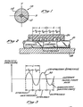
- a cross-section of an exemplary birefringent single mode optical fiber 10 is illustrated in Figure 1.
- the optical fiber 10 has an elliptical central core 12 having a relatively high index of refraction and has a surrounding cladding 14 which has a relatively low index of refraction.
- a birefringent optical fiber has two orthogonal principal axes of birefringence, each of which corresponds to a polarization mode or optical propagation path through the fiber 10. These axes are labeled X and Y in Figure 1. Each axis has a different effective refractive index.
- the two polarization modes of birefringent single mode optical fiber propagate light at slightly different velocities because of the differences in the refractive indices. Therefore, the phase of light propagating in the X-axis polarization mode will change relative to that in the Y-axis polarization mode as the light propagates down the fiber.
- the distance, measured longitudinally along the fiber, required for light in one mode to separate in phase by 360 degrees (2x radians) relative to the light in the other mode is commonly referred to as the "beat length" of the fiber.
- the beat length may be defined as follows: where Lg is the beat length, k is the free-space wavelength of the light, and An is the difference in the indices of refraction for the two polarization modes.
- the beat length is inversely proportional to the difference in the indices of refraction of the two optical propagation paths corresponding to the two polarization modes.
- the beat length is inversely proportional to the birefringence of the fiber 10. Consequently, a fiber having a relatively high birefringence has a shorter beat length than a fiber having a relatively low birefringence.
- One common technique for fabricating a high birefringence fiber is to draw the fiber such that the core has an elliptical shape, as illustrated by the core 12 in Figure 1.
- an elliptical core fiber manufactured by Andrew Corporation has a Y-axis measuring approximately one micrometer and has an X-axis measuring approximately two micrometers.
- the birefringence of the two axes of the core is approximately 3.72 x 10- 4 which provides a beat length of 1.7 millimeters at an optical wavelength of 633 nanometers.
- the outer diameter of the cladding of the fiber is approximately 50 micrometers.
- High birefringence fibers are advantageous in that the polarization modes are well-defined, and thus, the polarization of the applied light will be maintained over relatively long lengths of fiber, without significant coupling of light between the polarization modes.
- the polarization modes of a high birefringence fiber may be viewed as independent optical paths through the fiber, which are normally uncoupled such that light is not transferred between them.
- selective coupling of light between the polarization modes of a birefringent single mode fiber may be achieved by applying a force to the birefringent fiber at an angle of about 45° relevant to the principal axes of birefringence.
- Such force may be applied by squeezing the fiber between two plates on opposing sides of the fiber.
- Application of such force perturb the axes of birefringence at the point of force, and causes the axes of birefringence to be rotated through a small angle. Consequently, when light launched in one linearly polarized mode reaches the localized perturbation, the light will decompose into a superposition of modes linearly polarized along the perturbed axes of birefringence, effectively coupling light from one polarization mode to the other.
- the coupled light is not frequency shifted because the stresses in the fiber are static and do not travel down the fiber.
- FIG. 2 schematically depicts a ridge structure 20 comprising plural ridges 22, 24, 26 at spaced intervals.
- the fiber 10 is disposed between the ridges 22, 24, 26 and a base block 28, so that the fiber 10 may be squeezed therebetween.
- Application of force to the ridge structure 20 in a direction normal to the longitudinal axis of the fiber 10 perturbs the axes of birefringence at each of the ridges 22, 24, 26 and provides alternate stressed and unstressed regions along the fiber 10 which cause coupling between the two polarization modes of the fiber 10.
- the alternate stressed and unstressed regions provided by the ridge structure 20 of Figure 2 may be alternatively provided by an actual traveling acoustic wave, such as the acoustic wave 30 of Figure 3, which is launched to propagate longitudinally along the central axis of the fiber 10.
- the periodicity of the traveling acoustic wave 30 provides alternating regions of compression and rarefaction so as to provide corresponding alternating stressed and unstressed regions in the fiber, and thus, cause coupling between the polarization modes of the fiber.
- the wavelength of the acoustic wave 30 be selected such that it is equal to the beat length of the fiber 10.
- each of the alternating regions of compression and rarefaction will then be one-half beat length in length, and thus, each of the alternating stressed and unstressed regions will also be one-half beat length in length.
- the acoustic wave 30 of Figure 3 by providing alternating half beat length stressed and unstressed regions along the fiber 10, cumulatively couples light between the polarization modes of the fiber in much the same manner as the half beat length ridges 22, 24, 26 of Figure 2.
- cumulative coupling will also occur if the wavelength is an odd multiple of beat lengths.
- the fiber stress pattern produced by the traveling acoustic wave 30 of Figure 3 travels down the fiber 10.
- Such travel of the stress pattern causes the light coupled from one polarization mode to the other to be shifted in frequency much as light from a moving source is Doppler shifted.
- the optical carrier wave and the acoustic wave are heterodyned such that the acoustic frequency and the optical carrier frequency combine either additively or subtractively to provide a side band at either the sum or the difference frequency.
- the acoustic wave propagates in the same direction as the light, light coupled from the faster polarization mode to the slower polarization mode is upshifted in frequency, while light propagating from the slower polarization mode to the faster polarization mode is downshifted in frequency. If the acoustic wave propagates in a direction opposite to that of the optical carrier, these relationships are reversed, so that light coupled from the faster mode to the slower mode is downshifted, while light coupled from the slower mode to the faster mode is upshifted.
- Frequency shifted coupling requires that the acoustic wave be properly phased matched to the beat pattern of the optical modes in the fiber.
- phase matching occurs when the acoustic wavelength, as measured along the axis of the fiber 10 is equal to the beat length of the fiber.
- the propagation constant k 1 of the faster mode (lower effective refractive index), the propagation constant k 2 of the slower mode (higher effective refractive index), and the propagation constant k a of the acoustic wave should satisfy the following relationship:
- the acoustic propagation constant k a is the component of the acoustic propagation constant that is aligned with the optical propagation axis of the fiber.
- the frequency shifted coupling of light between the polarization modes may be examined mathematically by representing the light in the fast optical mode as cos ( ⁇ 1 t - k 1 z), where ⁇ 1 is the angular frequency of the light, t is time, and z is the distance along the fiber axis.
- the acoustic wave may be represented as cos( ⁇ a t - k a z), where w a is the angular frequency of the acoustic wave.
- the second term of Expression 3 does not satisfy the phase matching condition of Equation 2, and thus, it is expected that the signal represented by this term will die away.
- the first term is phase matched to the slow mode, in accordance with expression (2), and explicitly indicates that the slow mode is upshifted.
- a similar analysis shows that if the slow mode interacts with the acoustic wave, the expression for the resulting interaction is:
- the second term of Expression 4 like the second term of Expression 3, is not phased matched, however, the first term is phased matched to the fast mode in accordance with equation (2) and explicitly describes a downshifted wave.
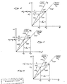
- the horizontal axis of the graph represents the magnitude of the propagation constant of the optical signal in the optical fiber 10.
- the vertical axis represents the magnitude of the frequency of the optical signal in the optical fiber 10.
- the relationship between the propagation constant and the frequency of an optical signal is dependent upon the propagation velocity in accordance with the following equations: where v 1 and v 2 are the propagation velocities of the optical signals in the fast propagation mode_and the slow propagation mode, respectively; ⁇ 1 and ⁇ 2 are the frequencies of the optical signals in the fast propagation mode and slow propagation mode, respectively; and k i and k 2 are the propagation constants of the optical signals in the fast propagation mode and slow propagation mode, respectively.
- a phantom line 100 representing the velocity v 1 of the optical signal in the fast propagation mode, has a greater slope (i.e., ⁇ / ⁇ k) than the slope of a phantom line 102, representing the velocity v 2 of the slow propagation mode.
- a vector 110 superimposed on the velocity line 100, has a length determined by the frequency ⁇ 1 and propagation constant k 1 of the optical signal input into the fiber 10 in the fast propagation mode.
- a vector 112 represents the acoustic wave 30 and has a slope, representing the velocity v a of the acoustic wave 30, in accordance with the following equation: The length of the vector 112 is determined by the frequency w a and is thus determined by the propagation constant k a .
- the vector 112 is added to the vector 110 to obtain a resulting vector 114 having a length on the k-axis equal to the sum of the optical propagation constant k 1 plus the acoustic propagation constant k a (i.e., k 2 - k 1 + k a ); and having a length along the w-axis equal to the sum of the input optical frequency w 1 plus the acoustic frequency ⁇ a (i.e., ⁇ 2 ⁇ 1 + ⁇ a ).
- the resulting vector has a slope equal to the velocity v 2 of the slow propagation mode so that the vector satisfies the phase matching condition for propagation along the optical path provided by the slow propagation mode.
- Figure 5 illustrates the phase-matching condition of Expression 4.
- a vector 120 represents the input optical signal in the slow propagation mode having a velocity v 2 , a frequency w 2 and a propagation constant k 2 .
- the resulting vector has a slope of ⁇ 1 /k 1 which corresponds to the slope of the graph 100 of the velocity v, for the fast propagation mode.
- the vector 124 represents an optical signal satisfying the phase-matching conditions for propagation in the fast optical propagation mode.
- Figure 6 graphically illustrates the result of using a higher frequency acoustic signal (e.g., an acoustic signal having a frequency ⁇ a ') such that the phase matching conditions are not met.
- a vector 130 represents the input optical signal in the fast propagation having a frequency ⁇ 1 and a propagation constant k 1 , corresponding to the velocity v 1 .
- a vector 132 represents the acoustic signal having a frequency wa and a propagation constant k a '. Assuming that the propagation velocity v a of the acoustic wave is the same as before, the acoustic vector 132 is necessarily longer than the corresponding acoustic vector 112 in Figure 4.
- a vector 134 representing the sum of the vector 130 and the vector 132 has a magnitude along the ⁇ -axis of ⁇ 2 ' - w 1 + ⁇ a' and a magnitude along the k-axis of k 2 ' - k 1 + k a '.
- the vector 132 does not have a slope corresponding to the slope of the velocity graph 102 for the slow propagation mode.
- the frequency-shifted optical signal is not properly phase-matched for propagation in the slow propagation mode and will not be supported in that propagation mode.
- phase matching requirements indicate that, for an acoustic wave propagating longitudinally down the fiber with the wave fronts normal to the fiber axis (i.e., an acoustic wave that propagates colinearly with the direction of propagation of the optical signals in the fiber), the acoustic wave frequency should be such that its wavelength is equal to the fiber beat length for the optical signal.
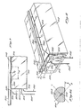
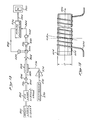
- FIG. 7 illustrates a preferred embodiment of the present invention.
- the present invention includes an optical fiber 300 which has an input end portion 302, an output end portion 304, and an interaction portion 306 lying between the input end portion 302 and the output end portion 304.
- the optical fiber 300 is placed in contact with the top surface 310 of a medium 312 for propagating a periodic traveling stress.
- the medium 312 is a bar of fused quartz having a generally rectangular cross section.
- the medium 312 has an end 314 which is preferably perpendicular to the top surface 310.
- An acoustic transducer 316 is mounted to the end 314 by bonding or other conventional means.
- the transducer 316 comprises a rectangular slab 320 of a piezoelectric materiaL, such as PZT (lead-zirconate-titanate).
- the transducer 316 further comprises a first electrode 322 which is mounted to the end 314 of the medium 312.
- the electrode 322 advantageously comprises Cr-Au, or another suitable material.
- the piezoelectric material 320 has a flat planar side surface (not shown) which is bonded to the first electrode 322.
- the piezoelectric material 320 has a second flat planar side surface 324, parallel to the first planar side surface, onto which a second electrode 326 is mounted, as shown.
- the piezoelectric material 320 has a top surface 330 that is substantially coplanar with the top surface 310 of the medium 312.
- the second electrode 326 is mounted on the second aide 324 such that it is positioned near the top surface 330.
- a first electrical interconnection line 332 and a second electrical interconnection line 334 are electrically connected to the first electrode -322 and the second electrode 326, respectively.
- the first and second lines 332 and 334 are connected to the output of a variable frequency voltage generator 336 that generates a time-varying voltage having a periodicity that can be varied.
- the time-varying voltage is applied to the first electrode 322 and the second electrode 326 to produce an electric field that causes the piezoelectric material 320 to vibrate.
- the piezoelectric material 320 operates in the shear mode to vibrate in the directions indicated by a double-headed arrow 338.
- the second electrode 326 has a vertical height, shown as H t in Figure 8, that is relatively short compared to the vertical height of the transducer so that the electric field is concentrated near the top of the transducer 316.
- H t the vertical height of the transducer
- substantially all of the vibration is concentrated near the top of the transducer 316.
- the piezoelectric material 320, the first electrode 322 and the end 314 of the medium 312 are bonded together so that the vibration of the piezoelectric material 320 induces vibrations in the top surface 310 of the medium 312.
- the surface acoustic wave 342 propagates away from the transducer 316 as a traveling surface acoustic wave which interacts with the fiber 300 in the interaction region 306, through a length referred to herein as the interaction length.
- the traveling surface acoustic wave causes undulations in the top surface 310 of the medium 312 which cause a periodic traveling stress to the optical fiber 300.
- an optical signal propagating in the fiber 300 in one propagation mode will be coupled to the other propagation mode over the interaction length of the interaction portion 306.
- the amount of coupling is dependent upon the degree of phase-matching (i.e., it depends upon how close the optical beat length of the optical signal within the fiber is matched to the acoustic wavelength of the traveling acoustic wave 342).
- the amount of coupling also depends upon the interaction length (i.e., the length of the portion 306) over which the traveling acoustic wave 342 interacts with the optical fiber 300, and upon the intensity of the traveling acoustic wave 342.
- the present invention advantageously includes a means 350 for channeling the surface acoustic wave 342 along an area in the immediate proximity of the optical fiber 300.
- the channeling means is illustrated in detail in Figures 7 and 8 as an acoustic propagation waveguide or channel 350 for the preferred embodiment.
- the acoustic propagation channel 350 comprises a thin metallic film 350, such as a thin film 350 of gold.
- the thin gold film 350 is evaporation deposited on the top surface 310 of the medium 312.
- the thin film 350 has a thickness of approximately 5 microns between the optical fiber 300 and the top surface 310. The thickness is shown as the dimension T c in Figure 9.
- the thickness of the thin gold film 350 is exaggerated in Figures 8 and 9.
- the deposition of the thin metallic film 350 onto the surface 310 of the fused quartz medium 312 produces an acoustic channel which confines the surface acoustic wave 342 ( Figure 9) to the area of the thin film 350.
- the etfect of the thin gold film 350 on the surface 3-10 of the fused quartz 312 is to cause a slower propagation velocity for that portion of the surface 310 covered by the gold film 350.
- the acoustic wave 342 propagating along the top surface 310 is well confined by the area defined by the thin gold film 350.
- the velocity of the acoustic wave 342 in the acoustic propagation channel 350 will be referred to hereinafter as v a .
- the thin gold film 350 advantageously has a width W c ( Figure 8) which is selected to be approximately 10 to 25 times the diameter of the optical fiber 300.
- an exemplary optical fiber 300 has a diameter of approximately 40 microns.
- the width of the channel is advantageously between 0.4 millimeters and 1.0 millimeters.
- the width W . is selected to optimize the channeling of the acoustic wave for a selected range of frequencies.
- the width W c is chosen to be sufficiently narrow to ensure that the acoustic waveguide formed by the channel 350 supports only a single acoustic mode, but not so narrow that the single acoustic mode is not well guided.
- the channel 350 preferably has an enlarged end portion 352 proximate to the end 314 of the medium 312.
- the enlarged portion 352 has a width proximate to the end 314 which is approximately the same width as the transducer 316.
- ⁇ the width of the enlarged portion 352 proximate to the end 314 is slightly larger than-the width of the transducer 316.
- the width of the enlarged portion 352 tapers gradually to the width W c , as illustrated.
- the enlarged portion 352 of the acoustic channel 350 serves as an acoustic horn which funnels the acoustic waves generated by the transducer 316 down to the width W c .
- the acoustic transducer 316 can advantageously have a width larger than the main portion of the acoustic channel 350 so that more acoustic power can be generated by the transducer 316.
- the acoustic horn formed by the enlargd portion 352 guides the acoustic waves 342 generated by the transducer 316 and causes them to be concentrated in the acoustic channel defined by the gold film 350.
- the channel 350 has a length, shown as L . in Figure 7, that is approximately 150 millimeters.
- L c of 150 millimeters corresponds to approximately 120 beat lengths (i.e., 120 L B ).
- the length of the interaction portion 306 is approximately equal to the length L . of the channel 350.
- the present invention is constructed so that the interaction length is equal to a large number of beat lengths (e.g., greater than about 100) to provide a very narrow range of optical frequencies (i.e., a very narrow optical bandwidth) over which the coupling between propagation modes is substantial. It has been found that for a frequency shifter having an acoustic wavelength matched with a selected center optical wavelength ⁇ 0 , such that the maximum coupling between the polarization modes occurs for the optical wavelength ⁇ 0, that the 3-dB bandwidth is approximately equal to 0.8 ⁇ 0/N, where N is the number of beat lengths over which the optical signal and the acoustic waves interact.
- the bandwidth (referred to as the full width at half maximum, i.e., FWHM) is approximately 48 nanometers.
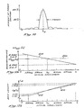
- the interaction length of 120 beat lengths provides an optical bandwidth at 600 nanometers of approximately 4 nanometers (i.e., FWHM - 4nm). This is illustrated in Figure 10 which is a graph of coupled output power versus wavelength.
- the present invention is particularly well-suited for use as a tunable optical filter.
- the present invention operates as a tunable filter as follows.
- An optical signal is introduced into the end portion 302 of the optical fiber 300 and is caused to propagate through the intermediate portion 306 of the optical fiber.
- the variable frequency source 340 is adjusted to generate an electrical signal that can be varied over a range of frequencies.
- the wavelength of the acoustic wave 342 generated by the transducer 310 will also vary in accordance with the frequency of the voltage applied across the electrodes 322 and 326 from the variable frequency voltage source 340.
- the acoustic channel formed by the thin gold film 350 and the fused quartz of the medium 312 has an acoustic propagation velocity of approximately 3345 meters per second.
- the acoustic wavelength h a is approximately 1.239 millimeters.
- an optical signal having a wavelength of approximately 603 nanometers and a birefringence An eff at 603 nanometers of approximately 4.866 x 10- 4 will have a beat length between the two polarization modes of approximately 1.239 millimeters.
- an optical signal introduced into the first end portion 302 of the optical fiber 300 in one polarization mode at an optical wavelength of 603 nanometers will have a substantial portion of the optical energy coupled from the input polarization mode to the other polarization mode as it propagates through the intermediate portion 306 of the optical fiber 300 and will exit through the second end portion 304 in the second polarization mode.
- An optical signal having a wavelength less than or greater than 603 nanometers will have a smaller percentage of the optical power coupled from the first polarization mode to the second polarization mode.
- the optical wavelength for which the maximum coupling between the polarization modes occurs can be selected by varying the frequency of the output voltage provided by the variable frequency voltage source 340.
- the apparatus illustrated in Figure 7 operates as a tunable optical filter. For example, at an acoustic frequency of 2.6 MHz, corresponding to an acoustic wavelength of 1.287 millimeters, the present invention will pass a small band of wavelengths centered around an optical wavelength of approximately 625 nanometers.
- the present invention is particularly advantageous for use in determining the wavelength content of an optical signal comprising one or more unknown optical wavelengths.
- the present invention can be used as an optical spectrum analyzer.
- the input polarizer 360 is advantageously constructed in accordance with U.S. Patent No. 4,386,822.
- the input polarizer 360 has an input end 362 and an input end 364.
- the input end 362 is positioned to receive an input optical signal, shown as W IN , and represented by an arrow 366.
- the output end 364 is optically connected to the input end portion 302 of the fiber 300.
- the polarizer 360 is positioned and adjusted so that it transmits only light that is polarized along one of the two orthogonal polarization axes of the fiber 300. That polarization axis will be referred to hereinafter as the first polarization axis.
- the first polarization axis will be referred to hereinafter as the first polarization axis.
- the present invention further includes an output polarizer 370 having an input end 372 connected to the output end portion 304 of the fiber 300 and having an output end 374.
- the output polarizer 370 is adjusted so that it is aligned with the second polarization axis of the fiber 300 so that only light that has been coupled to the second polarization mode is transmitted by the output polarizer 370.
- an optical signal transmitted by the input polarizer 360 and entering the end portion 302 of the optical fiber 300 in the first polarization mode and continuing through the optical fiber 300 in the first polarization mode will not be transmitted by the polarizer 370.
- the output polarizer 370 will transmit only that optical energy which has been coupled from the first polarization mode to the second polarization mode as a result of the stresses caused by the traveling acoustic wave 342 ( Figure 9).
- the output signal from the polarizer 370 is shown as an arrow 380 and is labelled WOUT .
- the output signal W OUT is directed at a photodetector 382.
- the photodetector 382 generates an electrical output signal having a magnitude proportional to the intensity of the optical output signal W OUT .
- the output signal from the photodetector 382 is a voltage having a magnitude proportional to the optical intensity in the optical output signal W OUT .
- the output of the photodetector 382 is applied through a line 384 to one input of an electronic measuring device 390, which, in the embodiment shown, is an oscilloscope.
- the line 384 is connected to the vertical input of the oscilloscope (V) so that the magnitude of the voltage on the line 384 controls the vertical deflection of the oscilloscope as displayed on a display screen 392.
- the horizontal input (H) of the oscilloscope is connected via a line 394 to an output from the variable frequency voltage source 336 that is proportional to the periodicity of the signal generated by the voltage source.
- the voltage on the line 394 can be advantageously calibrated to be equal to zero volts for a minimum acoustic wavelength and equal to a voltage corresponding the maximum horizontal deflection for the maximum acoustic wavelength.
- variable frequency voltage source is repetitively varied between a frequency corresponding to the minimum acoustic wavelength and a frequency corresponding to the maximum acoustic wavelength so that the voltage on the line 394 provides a repeating horizontal sweep for the oscilloscope.
- the acoustic wavelength of the acoustic wave 342 generated by the transducer 316 varies between its minimum and maximum wavelength.
- the acoustic wavelength corresponds to the beat length of an optical component of the input optical signal W IN , a substantial portion of the input optical energy at that wavelength will be coupled from the input polarization mode to the orthogonal polarization mode and will be transmitted by the output polarizer 370 and detected by the detector 382.
- the detector 382 will generate a voltage on the line 384 which is proportional to the power in the detected signal. -
- a relatively large vertical deflection on the display 392 of the oscilloscope 390 will occur when the acoustic wavelength matches the optical beat length. Since the relationship between the acoustic wavelength and the optical beat length, and thus the relationship between the acoustic wavelength and the optical wavelength, can be calculated, as will be described in detail below, the horizontal deflection of the oscilloscope can be calibrated in increments of optical wavelength.
- the display 392 on the oscilloscope 390 will display the wavelengths of the spectral components of the input optical signal W IN as peaks in the vertical deflection.
- the present invention provides a means of determining the spectral content of the input optical signal W I N.
- an optical fiber 400 having a D-shaped cross-section, as illustrated in Figure 8b is advantageously used.
- the D-shaped fiber 400 is manufactured by Andrew Corporation, 10500 West 153rd Street, Orland Park, Illinois 60462.
- the D-shaped fiber 400 has an elliptical core 402 and an outer cladding 404.
- the cladding 404 is generally circular but has a flat surface 406 on one side thereof.
- the elliptical core 402 is oriented with respect to the flat surface 406 such that the major axis X is at an angle + with respect to the flat surface 406.
- the angle # is substantially equal to 45°.
- the flat surface 406 greatly facilitates the orientation of the two orthogonal axes with the upper surface 310 of the medium 312.
- a description of a D-shaped fiber having a core with the principle axis parallel to the flat surface can be found in R.B. Dyott, et al., "Self-Locating Elliptically Cored Fiber with an Accessible Guiding Region,” ELECTRONICS LETTERS, Vol. 18, No. 22, October 28, 1982, pp. 980-981.
- the same techniques described therein can be used to construct the D-shaped fiber with the principle axis at an angle to the flat surface.
- Figures 11a, 11b, 11c and 11d illustrate,the above- described operation of the present invention as an optical analyzer.
- Figure 11a is a graph of the acoustic wavelength with respect to time.
- the voltage source 340 ( Figure 7) is adjusted so that the acoustic wavelength varies between a first acoustic wavelength ⁇ a1 and a second acoustic wavelength ⁇ a2.
- the acoustic wavelength varies substantially linearly between the first and second wavelengths.
- the acoustic wavelength reaches the second acoustic wavelength ⁇ a2 it is returned relatively rapidly to the first wavelength and again increases linearly to the second wavelength.
- This process is repeated continuously, with a periodicity of T, so as to generate a bright trace on the oscilloscope display 392 responsive to the horizontal sweep generated by the output voltage from the voltage source 340 on the line 394.
- the oscilloscope can be replaced with an active recording device, for example, a digital-to-analog converter and a microprocessor (not shown), so that it is only necessary to sweep through the acoustic wavelengths a single time.
- an active recording device for example, a digital-to-analog converter and a microprocessor (not shown)
- Figure 11b is a graph of the optical center wavelength ⁇ 0 with respect to time.
- the optical center wavelength ⁇ 0 is the wavelength having a beat length L B substantially equal to the acoustic wavelength ⁇ a
- the optical center wavelength ⁇ 0 varies in accordance with the acoustic wavelength ⁇ a.
- an optical center wavelength ⁇ 01 corresponds to the optical wavelength having a beat length that is substantially equal to the wavelength ⁇ a1.
- the optical center wavelength ⁇ g2 has a beat length which is substantially equal to the acoustic wavelength ⁇ a2 .
- the change in optical center wavelength from the first optical center wavelength ⁇ 01 to the second optical center wavelength ⁇ 02 is illustrated as a linear increase in optical wavelengths; however, as will be explained below, the optical center frequency is not necessarily a linear function of the acoustic wavelength.
- Figure 11c is a graph of the acoustic frequency with f a with respect to time that corresponds to the acoustic wavelengths in Figure 11a.
- the acoustic frequency f a is a non-linearly decreasing function with respect to time since the acoustic frequency is equal to va/ ⁇ a. It can be shown that the acoustic frequency required to cause a linear scan of acoustic wavelengths from the first acoustic wavelength ⁇ a1 to the second acoustic wavelength ⁇ a2 over a period of time labelled as T, varies according to the relation:
- Figure 11d illustrates an exemplary oscilloscope trace of output intensity versus time when an input optical signal has an optical wavelength ⁇ 0 that is approximately half way between the optical wavelength ⁇ 01 and the optical wavelength ⁇ 02. It should be understood that the vertical scale in Figure 11d corresponds to the vertical deflection on the oscilloscope screen. Thus, Figure 11d is the superposition of the traces which occur during each repetition period T.
- the line 402 can be represented mathematically as follows: wherein ⁇ 0 is a selected center frequency, ⁇ n eff ( ⁇ ) is the effective birefringence as a function of wavelength, ⁇ n eff ( ⁇ 0 ) is the effective birefringence at the selected center frequency ⁇ 0 , and ⁇ is a variance which can be determined for each optical fiber.
- the center wavelength, ⁇ 0 was 602.91 nm
- ⁇ was -0.228
- An eff ( ⁇ 0 ) was 4.8661 x 10- 4 .
- the negative variance ⁇ causes the change in birefringence to be a decreasing function of the wavelength.
- the effective refractive index varies from 4.9082 x 10- 4 at 580 nm to 4.8162 x 10- 4 at 630 nm.
- the beat length L B is a function of the optical wavelength and the birefringence (i.e., L B -[ ⁇ / ⁇ n eff ( ⁇ ]), the beat length L B is not a linear function of optical wavelength as was assumed in the foregoing discussion. Rather, the optical beat length L B increases non-linearly with respect to wavelength. This is illustrated more clearly in Figure 12b which is a graph of optical beat length L B versus optical wavelength X (i.e., a graph of L B (X)).
- the optical beat length L B at the center frequency ⁇ 0 is 1.239 nm. If the birefringence were constant over the frequency range, the optical beat length at 580 nm would be 1.191 nm and the beat length at 630 nm would be approximately 1.295 mm. This relationship is illustrated by a straight line 410, shown in phantom. A better approximation to the change in beat length L B with respect to the optical wavelength X is represented by a curved line 412.
- the optical beat length L B is equal to 580 nm/4.9082 x 10 -4 or 1.182 mm, which is less than the predicted wavelength for the linear model.
- the optical beat length L B is approximately equal to 1.308 mm which is greater than the corresponding beat length for the linear model.
- the non-linear graph 412 passes through the linear graph 410 at the selected center wavelength ⁇ 0 .
- the graph 412 in Figure 12b appears to be a straight line, one skilled in the art will realize that it is a non-linear function of the wavelength ⁇ .
- the mathematical expression for the graph 412 can be derived as follows: where L B ( ⁇ 0 ) is the beat length at the selected center frequency ⁇ 0.
- FIG. 13 An experimental embodiment for testing the present invention is illustrated in Figure 13.
- an argon laser 500 operating at a wavelength of approximately 514.5 nm, generates an output signal which is provided as an input to a tunable dye laser 502.
- the dye laser was tunable over a range of 570 nm to 630 nm.
- the output of dye laser is directed through a polarizer 504.
- the polarizer 504 passes light having a single linear polarization, hereinafter the first polarization.
- the output of polarizer 504 is passed through a lens 506, which is focused onto the input of a birefringent fiber 520.
- the birefringent fiber 520 is part of a narrow band tunable filter 522 that is constructed in accordance with Figures 7, 8 and 9.
- the output of the tunable filter 522 is directed at an output lens 524 which directs the light towards a beam splitter 530.
- Approximately 50X of the light entering the beam splitter 530 is directed towards an output polarizer 540.
- the output polarizer 540 is adjusted to pass only that light which is linearly polarized orthogonal to the first polarization.
- the output of the output polarizer 540 is directed onto a detector 542 which is responsive to the intensity of the light passing through polarizer 540 and generates an electrical output signal on a line 544 which is connected to one input of an analog ratiometer 546.
- approximately half of the optical energy incident on the beam splitter 530 is directed towards a second detector 550.
- the second detector 550 produces an output signal on a line 552 that is responsive to the intensity of the light incident on the detector 550.
- the line 552 is connected to a second input of the ratiometer 546.
- the analog ratiometer 546 operates in a known manner to generate an output signal on a line 554 which is proportional to the ratio of the input voltage on the line 544 to the input voltage on the line 552.
- the output on the line 554 has a magnitude which is proportional to the percentage of the input optical energy which is coupled to the second orthogonal polarization mode.
- the analog ratiometer 546 is used in the experimental set-up because the dye laser 502 does not generate a constant magnitude output over the entire wavelength range. Thus, the ratiometer 546 generates an output signal proportional to the percentage of coupling to the second polarization rather than to the absolute power coupled to the second polarization. -If a tunable laser having a constant magnitude output over the wavelength range is used, the output of the first detector 542 can be used directly as the output signal.
- the signal output of the analog ratiometer 546 on the line 554 is provided as an input to an analog recording device 560, such as recording oscillograph.
- the recording device 560 records the output signal as a function of time.
- the output wavelength of the dye laser 502 is varied linearly with respect to time so that the time seale on the recording device is proportional to the optical wavelength.
- the experimental embodiment further includes a frequency synthesizer 570 which provides a variable frequency output signal on a line 572 to the input of an amplifier 574.
- the ampiifier 574 provides an output on a line 576 which is provided an electrical input signal to the transducer of the tunable filter 522.
- the synthesizer operates in a conventional manner to generate an electrical output signal which varies in frequency over a selectable range.
- the frequency generated by the aynthesizer was varied in 0.05 MHz increments between 2.55 MHz and 2.85 MHz to verify the tunability of the tunable filter 522.
- the experimental results are illustrated in Figures 14a, 14b, 14c, 14d, 14e, 14f and 14g.
- the acoustic was held constant at each of the steps and the optical input signal frequency was waried by varying the output of the dye laser 502.
- the acoustic frequency generated by the synthesizer was set at 2.55 MHz.
- the recording oscillograph recorded a maximum amplitude of the output signal on the line 544 at a time corresponding to an optical wavelength of approximately 630 nm.
- the synthesizer was adjusted to provide an output signal at 2.60 MHz.
- the peak magnitude of the output 554 occurred at approximately 622 nm.
- the output on the line 544 had a peak magnitude at approximately 612 nm as illustrated in Figure 14c.
- the output signal on the line 554 had a peak magnitude at approximately 603 nm, as illustrated in Figure 14d.
- the output on the line 554 had a peak magnitude at approximately 594 nm, as illustrated in Figure 14e.
- the output signal on the line 554 had a peak magnitude at an optical wavelength of approximately 585 nm, as illustrated in Figure 14f.
- the output signal on the line 554 had a peak magnitude at an optical wavelength of approximately 575 nm, as illustrated in Figure 14g.
- an optical fiber 600 is wound around a cylindrical acoustic substrate 602 having a diameter D.
- a transducer 604 positioned at one end of the substrate 602 causes a surface acoustic wave to propagate through the acoustic substrate 602 and periodically stress the fiber 600.
- the fiber 600 is wound with a constant pitch angle e which is selected so that the acoustic wavelength in the direction of the longitudinal axis of the optical fiber 600 is equal to the beat length of the optical signal in the fiber 600.
- a large interaction length can be provided by wrapping the fiber 600 around the acoustic substrate 602.
- This embodiment can be advantageous in applications wherein a shorter acoustic propagation length is desired for the equivalent interaction length.
- higher acoustic frequencies can be used in this embodiment.
- the embodiment described in Figure 15 is described more fully in connection with its use in a frequency shifter in United States Patent Application Serial No. 699,666, entitled “Acousto-Optic Frequency Shifter Utilizing Multi-Turn Optical Fiber", filed on February 8, 1985, and assigned to the assignee of the present invention.
- the patent application is incorporated herein by reference.
Landscapes
- Physics & Mathematics (AREA)
- General Physics & Mathematics (AREA)
- Spectroscopy & Molecular Physics (AREA)
- Optics & Photonics (AREA)
- Nonlinear Science (AREA)
- Optical Modulation, Optical Deflection, Nonlinear Optics, Optical Demodulation, Optical Logic Elements (AREA)
- Spectrometry And Color Measurement (AREA)
- Agricultural Chemicals And Associated Chemicals (AREA)
Applications Claiming Priority (2)
| Application Number | Priority Date | Filing Date | Title |
|---|---|---|---|
| US83045786A | 1986-02-18 | 1986-02-18 | |
| US830457 | 1986-02-18 |
Publications (2)
| Publication Number | Publication Date |
|---|---|
| EP0233748A2 true EP0233748A2 (de) | 1987-08-26 |
| EP0233748A3 EP0233748A3 (de) | 1990-01-03 |
Family
ID=25257038
Family Applications (1)
| Application Number | Title | Priority Date | Filing Date |
|---|---|---|---|
| EP87301134A Withdrawn EP0233748A3 (de) | 1986-02-18 | 1987-02-10 | Fiberoptisches Verfahren und Vorrichtung zum Filtern und Analysieren von Spektren |
Country Status (7)
| Country | Link |
|---|---|
| US (1) | US4781425A (de) |
| EP (1) | EP0233748A3 (de) |
| JP (1) | JPS62254020A (de) |
| KR (1) | KR870008199A (de) |
| AU (1) | AU6885887A (de) |
| IL (1) | IL81506A0 (de) |
| NO (1) | NO870608L (de) |
Cited By (3)
| Publication number | Priority date | Publication date | Assignee | Title |
|---|---|---|---|---|
| GB2197067A (en) * | 1986-09-19 | 1988-05-11 | Nat Res Dev | Optical fibres |
| WO1991010935A1 (en) * | 1990-01-16 | 1991-07-25 | British Telecommunications Public Limited Company | Optical attenuator |
| CN103180698A (zh) * | 2010-10-28 | 2013-06-26 | 英派尔科技开发有限公司 | 光声传感器 |
Families Citing this family (22)
| Publication number | Priority date | Publication date | Assignee | Title |
|---|---|---|---|---|
| JPH0718964B2 (ja) * | 1987-06-29 | 1995-03-06 | 日本電信電話株式会社 | 集積光デバイスおよびその製造方法 |
| US4929050A (en) * | 1988-10-31 | 1990-05-29 | Unisys Corporation | Traveling wave fiber optic interferometric sensor and method of polarization poling fiber optic |
| US5400171A (en) * | 1993-10-01 | 1995-03-21 | Bell Communications Research, Inc. | Acousto-optic filter with near-ideal bandpass characteristics |
| US5452314A (en) * | 1994-08-01 | 1995-09-19 | Hewlett-Packard Company | Controllable-birefringence, acousto-optic tunable filter and a laser tuned by the same |
| US5680495A (en) * | 1996-07-12 | 1997-10-21 | Bloom; Cary | Fiber optic device sealed by compressed metal seals and method for making the same |
| US5828802A (en) * | 1997-02-19 | 1998-10-27 | Lucent Technologies, Inc. | Self-tuning optical waveguide filter |
| US6801686B2 (en) * | 1997-06-06 | 2004-10-05 | Novera Optics, Inc. | Methods and apparatus for measuring the power spectrum of optical signals |
| US6539148B1 (en) | 1997-06-06 | 2003-03-25 | Novera Optics, Inc. | Channel equalizer with acousto-optic variable attenuators |
| US6510261B2 (en) | 1997-06-06 | 2003-01-21 | Novera Optics, Inc. | Acousto-optic variable attenuator with active cancellation of back reflections |
| US6266462B1 (en) * | 1998-02-12 | 2001-07-24 | Ultraband Fiber Optics | Acousto-optic filter |
| US6640027B2 (en) | 1997-06-06 | 2003-10-28 | Novera Optics, Inc. | Gain flattening tunable filter |
| US6850655B2 (en) | 1997-06-16 | 2005-02-01 | Novera Optics, Inc. | Optical apparatus with faraday rotator, static gain flattening filter and variable optical attenuator |
| US6357913B1 (en) * | 1998-02-12 | 2002-03-19 | Novera Optics, Inc. | Add/drop acousto-optic filter |
| US6535665B1 (en) * | 1998-02-12 | 2003-03-18 | Novera Optics, Inc. | Acousto-optic devices utilizing longitudinal acoustic waves |
| US6343165B1 (en) * | 1998-02-12 | 2002-01-29 | Novera Optics, Inc. | Optical add drop multiplexer |
| US6728026B2 (en) | 1998-07-14 | 2004-04-27 | Novera Optics, Inc. | Dynamically tunable optical amplifier and fiber optic light source |
| US6776536B1 (en) * | 2000-03-03 | 2004-08-17 | Axsun Technologies, Inc. | Integrated optical system monitoring system |
| US6904188B1 (en) | 2001-03-16 | 2005-06-07 | Novera Optics, Inc. | Acousto-optic tunable filter having improved wave-damping capability |
| US6826327B1 (en) | 2001-12-18 | 2004-11-30 | Novera Optics, Inc. | Tunable narrow band optical filter |
| US6700113B1 (en) | 2002-01-28 | 2004-03-02 | Novera Optics, Inc. | Method, apparatus, and system for reducing intensity modulation |
| US8309045B2 (en) | 2011-02-11 | 2012-11-13 | General Electric Company | System and method for controlling emissions in a combustion system |
| JP7287008B2 (ja) * | 2019-03-04 | 2023-06-06 | 日本電信電話株式会社 | 音響モード伝搬速度測定方法及び音響モード伝搬速度測定装置 |
Family Cites Families (17)
| Publication number | Priority date | Publication date | Assignee | Title |
|---|---|---|---|---|
| US3409848A (en) * | 1967-10-30 | 1968-11-05 | Bell Telephone Labor Inc | Elastic surface waveguide |
| US3625589A (en) * | 1969-08-19 | 1971-12-07 | American Optical Corp | Apparatus for controlling the propagation characteristics of coherent light within an optical fiber |
| US3645603A (en) * | 1969-09-24 | 1972-02-29 | Luther W Smith | Light modulation in optic fiber |
| US3931518A (en) * | 1974-11-11 | 1976-01-06 | Bell Telephone Laboratories, Incorporated | Optical fiber power taps employing mode coupling means |
| JPS5241541A (en) * | 1975-09-29 | 1977-03-31 | Nippon Telegr & Teleph Corp <Ntt> | Input-output equipment for optical fibers |
| US4018506A (en) * | 1975-11-12 | 1977-04-19 | Rca Corporation | Fiber-optic to planar-waveguide optical coupler |
| JPS5267345A (en) * | 1975-12-01 | 1977-06-03 | Nippon Telegr & Teleph Corp <Ntt> | Mixing device for optical fiber modes |
| US4086484A (en) * | 1976-07-14 | 1978-04-25 | International Telephone And Telegraph Corporation | Optical amplitude modulation modulator |
| US4319186A (en) * | 1978-05-05 | 1982-03-09 | National Research Development Corporation | Signal sensors |
| US4236786A (en) * | 1978-12-13 | 1980-12-02 | Corning Glass Works | Method of effecting coupling of selected modes in an optical waveguide |
| DE3006102A1 (de) * | 1979-02-19 | 1980-08-28 | Ricoh Kk | Optische steuereinrichtung |
| JPS55155324A (en) * | 1979-05-23 | 1980-12-03 | Ricoh Co Ltd | Optical fiber device |
| US4268116A (en) * | 1979-10-26 | 1981-05-19 | Optelecom Incorporated | Method and apparatus for radiant energy modulation in optical fibers |
| JPS57158616A (en) * | 1981-03-25 | 1982-09-30 | Ricoh Co Ltd | Optical coupler |
| JPS58140715A (ja) * | 1982-02-15 | 1983-08-20 | Nippon Telegr & Teleph Corp <Ntt> | 光波長変換素子 |
| US4684215A (en) * | 1983-11-30 | 1987-08-04 | The Board Of Trustees Of The Leland Stanford Junior University | Single mode fiber optic single sideband modulator and method of frequency |
| US4735485A (en) * | 1984-02-17 | 1988-04-05 | The Board Of Trustees Of The Leland Stanford Junior University | Acousto-optic frequency shifter using optical fiber and method of manufacturing same |
-
1966
- 1966-02-18 US US06/830,457 patent/US4781425A/en not_active Expired - Fee Related
-
1987
- 1987-02-09 IL IL81506A patent/IL81506A0/xx unknown
- 1987-02-10 EP EP87301134A patent/EP0233748A3/de not_active Withdrawn
- 1987-02-17 JP JP62034377A patent/JPS62254020A/ja active Pending
- 1987-02-17 AU AU68858/87A patent/AU6885887A/en not_active Abandoned
- 1987-02-17 NO NO870608A patent/NO870608L/no unknown
- 1987-02-18 KR KR870001320A patent/KR870008199A/ko not_active Withdrawn
Cited By (4)
| Publication number | Priority date | Publication date | Assignee | Title |
|---|---|---|---|---|
| GB2197067A (en) * | 1986-09-19 | 1988-05-11 | Nat Res Dev | Optical fibres |
| WO1991010935A1 (en) * | 1990-01-16 | 1991-07-25 | British Telecommunications Public Limited Company | Optical attenuator |
| CN103180698A (zh) * | 2010-10-28 | 2013-06-26 | 英派尔科技开发有限公司 | 光声传感器 |
| CN103180698B (zh) * | 2010-10-28 | 2015-07-29 | 英派尔科技开发有限公司 | 光声传感器 |
Also Published As
| Publication number | Publication date |
|---|---|
| AU6885887A (en) | 1987-08-20 |
| NO870608L (no) | 1987-08-19 |
| US4781425A (en) | 1988-11-01 |
| KR870008199A (ko) | 1987-09-25 |
| JPS62254020A (ja) | 1987-11-05 |
| IL81506A0 (en) | 1987-09-16 |
| NO870608D0 (no) | 1987-02-17 |
| EP0233748A3 (de) | 1990-01-03 |
Similar Documents
| Publication | Publication Date | Title |
|---|---|---|
| US4781425A (en) | Fiber optic apparatus and method for spectrum analysis and filtering | |
| EP0144190B1 (de) | Einseitenband-Modulator mit einer optischen Monomode-Faser | |
| US4991923A (en) | Acousto-optic modulator for optical fibers using Hertzian contact with a grooved transducer substrate | |
| KR870001580B1 (ko) | 수동 간섭계식 감지기 어레이 | |
| US4515430A (en) | Integrated optical transducers | |
| EP1826545B1 (de) | Schadensdetektionssystem mit faseroptischen Sensoren | |
| US4735485A (en) | Acousto-optic frequency shifter using optical fiber and method of manufacturing same | |
| US4102579A (en) | Optical apparatus | |
| EP2470885B1 (de) | Photoakustischer sensor sowie verfahren zu seiner herstellung und verwendung | |
| US4793676A (en) | Optical fiber acousto-optic amplitude modulator | |
| US4792207A (en) | Single mode fiber optic single sideband modulator and method of frequency shifting using same | |
| US4801189A (en) | Birefringent fiber narrowband polarization coupler and method of coupling using same | |
| EP0190923B1 (de) | Optische Faser mit mehreren Windungen als akustooptischer Frequenzschieber | |
| DE4000800A1 (de) | Vorrichtung und verfahren zur verarbeitung von faseroptikrotationsfuehlersignalen | |
| DE3929340C2 (de) | ||
| Gu et al. | High-precision magnetic field sensor via optoelectronic oscillator having taper-based in-line modal interferometer | |
| EP0233749B1 (de) | Akusto-optischer, faser-optischer Frequenzumsetzer, der auf periodischem Kontakt mit einer akustischen Oberflächenwelle beruht | |
| EP0143583B1 (de) | Faseroptischer Modenkoppler | |
| US6647159B1 (en) | Tension-tuned acousto-optic bandpass filter | |
| US6556729B2 (en) | Acousto-optic bandpass filter | |
| EP0190922A2 (de) | Vorrichtung und Verfahren zur Bestimmung der Orientierung von Doppelbrechungsachsen in einer optischen Faser | |
| JPH0670656B2 (ja) | スペクトルアナライザ | |
| NO874794L (no) | Verktoey for avisolering av en elektrisk kabel. | |
| EP0183420A2 (de) | Akustooptischer Amplitudenmodulator mit einer optischen Faser | |
| JP2991261B2 (ja) | 光導波路型光周波数変換器 |
Legal Events
| Date | Code | Title | Description |
|---|---|---|---|
| PUAI | Public reference made under article 153(3) epc to a published international application that has entered the european phase |
Free format text: ORIGINAL CODE: 0009012 |
|
| AK | Designated contracting states |
Kind code of ref document: A2 Designated state(s): DE FR GB IT NL SE |
|
| PUAL | Search report despatched |
Free format text: ORIGINAL CODE: 0009013 |
|
| AK | Designated contracting states |
Kind code of ref document: A3 Designated state(s): DE FR GB IT NL SE |
|
| RHK1 | Main classification (correction) |
Ipc: G02F 1/01 |
|
| STAA | Information on the status of an ep patent application or granted ep patent |
Free format text: STATUS: THE APPLICATION IS DEEMED TO BE WITHDRAWN |
|
| 18D | Application deemed to be withdrawn |
Effective date: 19900704 |
|
| RIN1 | Information on inventor provided before grant (corrected) |
Inventor name: KINO, GORDON S. Inventor name: RISK, WILLIAM P. |