EP0234251A2 - Verfahren und Vorrichtung zum Nachweis von brennbaren Gasen - Google Patents
Verfahren und Vorrichtung zum Nachweis von brennbaren Gasen Download PDFInfo
- Publication number
- EP0234251A2 EP0234251A2 EP87100641A EP87100641A EP0234251A2 EP 0234251 A2 EP0234251 A2 EP 0234251A2 EP 87100641 A EP87100641 A EP 87100641A EP 87100641 A EP87100641 A EP 87100641A EP 0234251 A2 EP0234251 A2 EP 0234251A2
- Authority
- EP
- European Patent Office
- Prior art keywords
- measurement
- sensor
- reference value
- temperature
- heat
- Prior art date
- Legal status (The legal status is an assumption and is not a legal conclusion. Google has not performed a legal analysis and makes no representation as to the accuracy of the status listed.)
- Granted
Links
- 238000000034 method Methods 0.000 title claims abstract description 32
- 238000005259 measurement Methods 0.000 claims abstract description 94
- 239000007789 gas Substances 0.000 claims abstract description 46
- 239000000203 mixture Substances 0.000 claims abstract description 11
- 238000001514 detection method Methods 0.000 claims abstract description 6
- VNWKTOKETHGBQD-UHFFFAOYSA-N methane Chemical compound C VNWKTOKETHGBQD-UHFFFAOYSA-N 0.000 claims description 12
- 238000004880 explosion Methods 0.000 claims description 11
- 238000009529 body temperature measurement Methods 0.000 claims 1
- 230000006378 damage Effects 0.000 abstract description 5
- 238000005265 energy consumption Methods 0.000 abstract description 3
- 238000012544 monitoring process Methods 0.000 abstract 1
- 239000003054 catalyst Substances 0.000 description 3
- 238000007084 catalytic combustion reaction Methods 0.000 description 3
- QVGXLLKOCUKJST-UHFFFAOYSA-N atomic oxygen Chemical compound [O] QVGXLLKOCUKJST-UHFFFAOYSA-N 0.000 description 2
- 230000003197 catalytic effect Effects 0.000 description 2
- 238000002485 combustion reaction Methods 0.000 description 2
- 238000010586 diagram Methods 0.000 description 2
- 238000010438 heat treatment Methods 0.000 description 2
- 238000000691 measurement method Methods 0.000 description 2
- 239000001301 oxygen Substances 0.000 description 2
- 229910052760 oxygen Inorganic materials 0.000 description 2
- 230000005855 radiation Effects 0.000 description 2
- 230000000694 effects Effects 0.000 description 1
- 239000003344 environmental pollutant Substances 0.000 description 1
- 238000012423 maintenance Methods 0.000 description 1
- 238000012986 modification Methods 0.000 description 1
- 230000004048 modification Effects 0.000 description 1
- 230000007935 neutral effect Effects 0.000 description 1
- 238000011017 operating method Methods 0.000 description 1
- 231100000719 pollutant Toxicity 0.000 description 1
- 238000004321 preservation Methods 0.000 description 1
- 230000000717 retained effect Effects 0.000 description 1
Images

Classifications
-
- G—PHYSICS
- G01—MEASURING; TESTING
- G01N—INVESTIGATING OR ANALYSING MATERIALS BY DETERMINING THEIR CHEMICAL OR PHYSICAL PROPERTIES
- G01N33/00—Investigating or analysing materials by specific methods not covered by groups G01N1/00 - G01N31/00
- G01N33/0004—Gaseous mixtures, e.g. polluted air
- G01N33/0009—General constructional details of gas analysers, e.g. portable test equipment
- G01N33/0062—General constructional details of gas analysers, e.g. portable test equipment concerning the measuring method or the display, e.g. intermittent measurement or digital display
-
- G—PHYSICS
- G01—MEASURING; TESTING
- G01N—INVESTIGATING OR ANALYSING MATERIALS BY DETERMINING THEIR CHEMICAL OR PHYSICAL PROPERTIES
- G01N27/00—Investigating or analysing materials by the use of electric, electrochemical, or magnetic means
- G01N27/02—Investigating or analysing materials by the use of electric, electrochemical, or magnetic means by investigating impedance
- G01N27/04—Investigating or analysing materials by the use of electric, electrochemical, or magnetic means by investigating impedance by investigating resistance
- G01N27/14—Investigating or analysing materials by the use of electric, electrochemical, or magnetic means by investigating impedance by investigating resistance of an electrically-heated body in dependence upon change of temperature
-
- Y—GENERAL TAGGING OF NEW TECHNOLOGICAL DEVELOPMENTS; GENERAL TAGGING OF CROSS-SECTIONAL TECHNOLOGIES SPANNING OVER SEVERAL SECTIONS OF THE IPC; TECHNICAL SUBJECTS COVERED BY FORMER USPC CROSS-REFERENCE ART COLLECTIONS [XRACs] AND DIGESTS
- Y10—TECHNICAL SUBJECTS COVERED BY FORMER USPC
- Y10T—TECHNICAL SUBJECTS COVERED BY FORMER US CLASSIFICATION
- Y10T436/00—Chemistry: analytical and immunological testing
- Y10T436/21—Hydrocarbon
- Y10T436/214—Acyclic [e.g., methane, octane, isoparaffin, etc.]
-
- Y—GENERAL TAGGING OF NEW TECHNOLOGICAL DEVELOPMENTS; GENERAL TAGGING OF CROSS-SECTIONAL TECHNOLOGIES SPANNING OVER SEVERAL SECTIONS OF THE IPC; TECHNICAL SUBJECTS COVERED BY FORMER USPC CROSS-REFERENCE ART COLLECTIONS [XRACs] AND DIGESTS
- Y10—TECHNICAL SUBJECTS COVERED BY FORMER USPC
- Y10T—TECHNICAL SUBJECTS COVERED BY FORMER US CLASSIFICATION
- Y10T436/00—Chemistry: analytical and immunological testing
- Y10T436/21—Hydrocarbon
- Y10T436/218—Total hydrocarbon, flammability, combustibility [e.g., air-fuel mixture, etc.]
Definitions
- the invention relates to a method for the detection of the proportion of combustible gases in an air mixture with the aid of a measuring device equipped with a display unit, which works according to both the heat toning and the heat conduction method and a display according to the heat toning method only below a predefinable reference value for the measurement signal delivers.
- a measuring device for carrying out the method is specified.
- gas sensors are preferably used which contain a catalyst and are heated to a certain temperature (for example 500 ° C.), as a result of which the combustible gases burn catalytically on the sensor surface using part of the oxygen present in the measuring gas and raise the sensor temperature.
- a certain temperature for example 500 ° C.
- the heat that occurs during the combustion reaction is evaluated and displayed by means of the sensor temperature increase as a measurement signal for the concentration of the combustible gas in the air mixture to be examined.
- an active (detector) and a passive (compensator) sensor are usually arranged in a bridge half branch as the measuring device. This bridge is fed with either constant current or constant voltage.
- Such a measuring device works satisfactorily up to concentrations of 100% LEL (lower explosion limit) of the combustible gas in air.
- this limit is, for example, 5% by volume.
- this value result in increasing Measurements of temperature increase of the detector, residual activity of the compensator as well as oxygen depletion and thermal conductivity change of the gas mixture to a non-linear measurement signal with regard to the gas concentration.
- the output signal of the bridge is no longer clear, ie two gas concentrations are found for each value of the output voltage.
- the existing measuring bridge is supplemented by another branch, for example.
- a first sensor in the thermal bridge measuring bridge is kept at an operating temperature of approximately 500 ° C and another sensor in the thermal conductivity bridge at an operating temperature of, for example, 200 ° C.
- the sensor in the heat-measuring bridge provides a clear signal.
- the measuring device in the zero branch of the thermal radiation measuring bridge becomes full deflection switched, but the current or voltage supply of the thermal tone sensor is retained.
- the heat of combustion on the surface of the catalytic heat tone sensor increases in such a way that thermal destruction of the catalyst layer, or at least a considerable restriction of the usability of the sensor for further measurements, can result. Switching off the heating current then no longer helps to lower the operating temperature of the sensor, since the catalytic combustion continues at such high concentrations and continues until either the gas concentration drops or the catalyst is poisoned or the sensor is destroyed.
- both measuring bridges must be continuously supplied with electrical energy at the same time, in particular both sensors in the measuring bridges must remain heated to 200 ° C. or 500 ° C. in order to ensure constant readiness for measurement.
- this increased energy requirement requires a coordinated energy supply which, for example in the case of a portable measuring device, makes it necessary to carry large and heavy, and thus also cumbersome, batteries.
- the present invention has for its object to improve a method for the detection of flammable gases of the known type so that a clear measurement of the flammable gas in air in the entire concentration range from 0 to 100 vol .-% is possible with the lowest possible energy consumption.
- the measuring accuracy should be particularly high in the lower measuring range up to about the lower explosion limit.
- a measuring device which can be operated with such an improved method should have a smaller volume, be lighter and simpler for maintenance purposes and consist of fewer parts.
- the service life of the detection element should be increased.
- the object is achieved by a method which is characterized by the use of a single sensor element which is catalytically active at higher temperatures, the sensor being kept constant at the start of the measurement at a first temperature T 1 sufficient for the thermal conductivity measurement, the resulting measurement signal having a reference value R1 compared and if it falls below the reference value R1, the temperature of the sensor to a second temperature T2 enabling the tone measurement is increased and kept constant and the measurement signal emitted by the sensor is compared with a gas concentration corresponding to a higher concentration than R1 and its temperature lowered to the temperature T 1 and kept constant as soon as the measurement signal exceeds the limit value G.
- the heat tone measurement can be carried out more precisely than the thermal conductivity measurement, and the concentration of the combustible gas in the air mixture is displayed more precisely.
- the reference value R1 can thus be regarded as a threshold value, which marks the presence of combustible gases and switches the sensor early, at least before the lower explosion limit of the gas mixture is reached, at such low concentrations of combustible gas to the more accurate measurement of the heat tone, which damages the sensor cannot evoke. If the sensor is in the operating mode of the heat tone measurement, the measurement signal emitted by it is compared with a load limit value G. As long as the measurement signal falls below the limit value G, the sensor remains in the operating mode of the toning measurement. Is z. B. reached with increasing gas concentration this limit value G, the sensor is switched to the operating mode of thermal conductivity measurement and the lower operating temperature T1.
- the measurement is then carried out when the gas concentrations continue to rise, the measured values being able to be unambiguously assigned to the corresponding gas concentrations.
- the limit value G it is achieved that the Um circuit to the lower temperature T1 already takes place before self-preservation of the catalytic combustion can occur even without any electrical energy supply and could damage or destroy the sensor.
- the sensor is kept constant at the temperature T 2 required for this, without an uncontrolled heating being possible in the presence of combustible gases. Switching to the thermal conductivity measurement mode at an early stage protects the sensor from the destruction of its catalytic surface, which is necessary for the measurement of the heat, at increased concentrations of combustible gas. This increases the life of the sensor and limits the power consumption to what is necessary to maintain the operating temperature.
- the toning measurement is only carried out when the measurement signal is within a window between the reference values R1 and R2.
- a lower threshold value can be defined, below which the energy-saving thermal conductivity measurement is carried out and only when the reference value R2 is exceeded, the sensor is switched to the more accurate, but more energy-consuming, heat tone measurement.
- This method is particularly advantageous if there is an occurrence of combustible gases in substantial concentrations, ie. H. above the reference value R2 accordingly, is not expected.
- the reference value R1 or the exposure limit value G can be around 100 - 140% of the lower explosion limit (LEL), the second reference value R2 is in the range between 2% and 5% LEL.
- the method is used to advantageously monitor the concentration range below the lower explosion limit at significant concentrations with the precise measurement method of the tone measurement at elevated operating temperature T2 of the sensor and, as soon as the lower explosion limit is reached, the sensor according to the measurement method of thermal conductivity measurement at a lower operating temperature T1 to operate the sensor. As soon as the concentration of the combustible gas drops below the lower explosion limit, the sensor is automatically switched back to the measurement process of the heat tone measurement.
- An alarm system can also be activated if the second limit value is exceeded.
- a measuring device suitable for carrying out the method consists of a single sensor which is kept at a predetermined temperature by means of a controllable current source, which is constantly measured, monitored and compensated for with respect to the ambient temperature.
- An arithmetic unit compares the sensor signal with predetermined reference values R1, R2 or the load limit value G and decides, depending on the size of the measurement signal, whether the sensor is to be operated in the mode of heat tone measurement or in the mode of thermal conductivity measurement. A corresponding signal is sent to the power source. It is thus possible to carry out both operating modes for measuring the concentration of a combustible gas with a measuring circuit which can be used for both operating modes with only one sensor.
- the sensor 1 suitable for measuring thermal conductivity and toning is connected to a controllable current source 2 and a load resistor 3.
- the sensor resistance is measured above the sensor 1 with the aid of the amplifier 4 and processed in a computing unit 5, 6 as its temperature value.
- the measuring signal of the sensor is given via a measuring line 7 to the positive input of a measuring amplifier 8, the output of which is connected via the signal line 9 to a computing unit 5.
- the computing unit 5 continuously queries the reference lines R 1 and R 2 or the load limit G in the comparator 6 via the query lines 10, 11.
- the comparator 6 controls the current source 2 via a feedback l2 in such a way that it either maintains the temperature of the sensor l or for switching between the operating temperatures of the thermal conductivity measurement and the heat tone measurement, the current intensity which is output to the sensor l.
- the setpoint is corrected depending on the ambient temperature using a temperature sensor.
- the measured value determined by the computing unit 5 is displayed on a display unit l3. If the measurement signal from the signal line 9 is exceeded via the load limit value G, an alarm device 14 is activated in order to indicate acoustically or optically that the limit value has been exceeded.
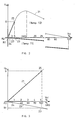
- the first measurement curve 2l shows the course of the measurement signal U s as a function of the concentration of the combustible gas in the air mixture in volume percent. It applies to the operating mode of the sensor 1 for the measurement of the heat tone. Their intersections lie with the abscissa at the point of origin and at 100% by volume. In between, it runs through a maximum.
- the second measurement curve 22 shows the linear signal curve of the measurement signal of the sensor 1 for the operating mode of the thermal conductivity measurement. It begins at the origin of the coordinate system and has a monotonous negative slope.
- the reference values R 1, R 2 and the limit value G are entered on the ordinate. Their intersections with the corresponding measurement curves are at 23 and 24 and 25 respectively.
- the sensor 1 When the measuring device is started up, the sensor 1 is first set by the current source 2 to the operating temperature T 1 suitable for the thermal conductivity measurement. Its measured values lie on the measurement curve 22. If measured values are detected by the arithmetic unit 5 which are below the limit value R 1, the arithmetic unit 5, 6 recognizes that combustible gas is present in a low concentration, and the sensor is switched to an operating temperature which enables the mode of heat tone measurement Brought T2. All measurements now taking place will lie on the measurement curve 2l due to the heat tone measurement. As long as the measurement signal U s is below the limit value G, the sensor 1 remains in the operating mode of the heat tone measurement.
- the arithmetic unit 5, 6 determines that concentrations of combustible gas above, for example, 5% by volume have been reached, and now causes the current source 2 to set the operating temperature of the sensor 1 to that for the operating mode of the Lowering the thermal conductivity measurement necessary lower operating temperature T1. With a further increase in the concentration of the combustible gas, the measurement is now carried out along the measurement curve 22 on the sub-area marked thick.
- the sensor 1 If the concentration of the combustible gas drops below 5% by volume, the sensor 1 is switched back to the mode of heat measurement and the further measurement takes place again along the thick section of the measurement curve 2l. In this way, depending on the level of the combustible gas, there is an alternating switching from one operating mode to another.
- the comparator 6 checks whether the resulting measurement signals are within a window between R1 and R2.
Landscapes
- Chemical & Material Sciences (AREA)
- Health & Medical Sciences (AREA)
- Life Sciences & Earth Sciences (AREA)
- Analytical Chemistry (AREA)
- General Health & Medical Sciences (AREA)
- Pathology (AREA)
- Immunology (AREA)
- Physics & Mathematics (AREA)
- Engineering & Computer Science (AREA)
- Biochemistry (AREA)
- General Physics & Mathematics (AREA)
- Combustion & Propulsion (AREA)
- Medicinal Chemistry (AREA)
- Food Science & Technology (AREA)
- Chemical Kinetics & Catalysis (AREA)
- Electrochemistry (AREA)
- Investigating Or Analyzing Materials By The Use Of Electric Means (AREA)
Abstract
Description
- Die Erfindung betrifft ein Verfahren zum Nachweis des Anteils von brennbaren Gasen in einem Luftgemisch mit Hilfe einer mit einer Anzeigeeinheit ausgestatteten Meßeinrichtung, die sowohl nach dem Wärmetönungs- als auch nach dem Wärmeleitungsverfahren arbeitet und eine Anzeige nach dem Wärmetönungsverfahren nur unterhalb eines vorgebbaren Referenzwertes für das Meßsignal abgibt. Außerdem wird eine Meßeinrichtung zur Durchführung des Verfahrens angegeben.
- Zum Nachweis und zur Messung von brennbaren Gasen werden bevorzugt Gassensoren eingesetzt, welche einen Katalysator enthalten und auf eine bestimmte Temperatur (beispielsweise 500 °C) erhitzt werden, wodurch die brennbaren Gase unter Verbrauch eines Teiles des in dem Meßgas vorhandenen Sauerstoffs an der Sensoroberfläche katalytisch verbrennen und die Sensortemperatur erhöhen. Die bei der Verbrennungsreaktion auftretende Wärmetönung wird vermittels der Sensortemperaturerhöhung als Meßsignal für die Konzentration des brennbaren Gases in dem zu untersuchenden Luftgemisch ausgewertet und angezeigt. Als Meßeinrichtung wird dazu üblicherweise ein aktiver (Detektor) und ein passiver (Kompensator) Sensor in einem Brückenhalbzweig angeordnet. Diese Brücke wird entweder mit Konstantstrom oder Konstantspannung gespeist. Eine solche Meßeinrichtung arbeitet zufriedenstellend bis zu Konzentrationen von l00 % UEG (Untere Explosionsgrenze) des brennbaren Gases in Luft. Diese Grenze beträgt für Methan beispielsweise 5 Vol.-%. Oberhalb dieses Wertes führen in zunehmendem Maße Temperaturerhöhung des Detektors, Rest-Aktivität des Kompensators sowie Sauerstoffverarmung und thermische Leitfähigkeitsveränderung des Gasgemisches zu einem nichtlinearen Meßsignal bezüglich der Gaskonzentration. Bei Gaskonzentrationen in einem Bereich oberhalb von l00 % UEG ist das Ausgangssignal der Brücke nicht mehr eindeutig, d. h. man findet pro Wert der Ausgangsspannung zwei Gaskonzentrationen. Um eindeutige Messungen von Konzentrationen über l00 % UEG zu erreichen, wird beispielsweise die vorhandene Meßbrücke um einen weiteren Zweig ergänzt. Dieser mißt dann ebenfalls in einer Brückenanordnung bei einer reduzierten Arbeitstemperatur von beispielsweise 200 °C nur die Änderung der thermischen Leitfähigkeit des den Sensor umgebenden Gasgemisches. Bei Erreichen eines bestimmten Schwellwertes für die thermische Leitfähigkeit, welcher im Bereich von l00 % UEG liegen kann, wird über ein geeignetes Schaltelement das im Nullzweig der Wärmetönungsmeßbrücke angeschlossene Anzeigeelement automatisch auf Vollausschlag umgeschaltet. Dadurch wird angezeigt, daß die Gasprobe eine Konzentration an brennbaren Gasen von über l00 % UEG enthält.
- Eine derartige Meßeinrichtung und das Verfahren zur Umschaltung zwischen Wärmeleitfähigkeits- und Wärmetönungsmessung ist in der DE-OS l6 73 306 beschrieben.
- Bei der bekannten Meßeinrichtung wird beispielsweise zur Methanmessung in Luft ein erster Sensor in der Wärmetönungsmeßbrücke auf einer Betriebstemperatur von etwa 500 °C und ein weiterer Sensor in der Wärmeleitungsmeßbrücke auf einer Betriebstemperatur von beispielsweise 200 °C gehalten. Im Meßbereich bis zu l00 % UEG liefert der Sensor in der Wärmetönungsmeßbrücke ein eindeutiges Signal. Oberhalb der Grenze von l00 % UEG wird zwar das Meßgerät im Nullzweig der Wärmetönungsmeßbrücke auf Voll ausschlag geschaltet, die Strom- bzw. Spannungsversorgung des Wärmetönungssensors bleibt jedoch erhalten. Bei weiterer Erhöhung des Methangehaltes in dem Luftgemisch über l00 % UEG hinaus erhöht sich die Verbrennungswärme an der Oberfläche des katalytischen Wärmetönungssensors derart, daß eine thermische Zerstörung der Katalysatorschicht, mindestens jedoch eine erhebliche Einschränkung der Brauchbarkeit des Sensors für weitere Messungen die Folge sein kann. Hier hilft dann auch kein Abschalten des Heizstromes mehr, um die Betriebstemperatur des Sensors zu senken, da die katalytische Verbrennung bei solch hohen Konzentrationen von selbst weiterläuft und so lange anhält, bis entweder die Gaskonzentration absinkt oder der Katalysator vergiftet bzw. der Sensor zerstört ist.
- Nach dem Umschalten des im Nullzweig der Wärmetönungsmeßbrücke befindlichen Anzeigegerätes auf Vollausschlag ist eine Messung der Konzentration des tatsächlich im Luftgemisch vorhandenen nachzuweisenden Schadstoffes nicht mehr möglich.
- Bei der bekannten Meßeinrichtung müssen zwei Meßbrücken zur gleichen Zeit kontinuierlich mit elektrischer Energie versorgt werden, insbesondere müssen beide in den Meßbrücken befindliche Sensoren auf 200 °C bzw. 500 °C angewärmt bleiben, um eine ständige Meßbereitschaft zu gewährleisten. Dies bedeutet einen erhöhten Energieverbrauch, da beide Sensoren gleichzeitig auf ihrer jeweiligen Betriebstemperatur gehalten werden müssen, obwohl nur einer von beiden für die tatsächliche Messung bzw. für die Bestimmung des Zeitpunktes für die Umschaltung des Meßgerätes auf Vollauschlag erforderlich wäre. Dieser erhöhte Energiebedarf verlangt bei entsprechender Einsatzdauer eines Meßgerätes eine darauf abgestimmte Energieversorgung, die beispielsweise bei einem tragbaren Meßgerät das Mitführen von geräumigen und schweren, und damit auch hinderlichen, Batterien notwendig macht.
- Der vorliegenden Erfindung liegt die Aufgabe zugrunde, ein Verfahren zum Nachweis von brennbaren Gasen der bekannten Art so zu verbessern, daß eine eindeutige Messung des brennbaren Gases in Luft im gesamten Konzentrationsbereich von 0 bis l00 Vol.-% bei geringstmöglichem Energieverbrauch möglich ist. Dabei soll die Meßgenauigkeit im unteren Meßbereich bis etwa zur Unteren Explosionsgrenze besonders hoch sein. Ein Meßgerät, welches mit einem derartigen verbesserten Verfahren betrieben werden kann, soll ein kleineres Volumen besitzen, leichter und zum Zwecke der Wartung einfacher sein und aus weniger Teilen bestehen. Die Lebensdauer des Nachweiselementes soll erhöht werden.
- Die Lösung der Aufgabe erfolgt durch ein Verfahren, welches durch die Verwendung eines einzigen, bei höheren Temperaturen katalytisch aktiven Sensorelementes gekennzeichnet ist, wobei der Sensor zu Beginn der Messung auf einer für die Wärmeleitfähigkeitsmessung ausreichenden ersten Temperatur T₁ konstant gehalten, das resultierende Meßsignal mit einem Referenzwert R₁ verglichen und wenn es den Referenzwert R₁ unterschreitet, die Temperatur des Sensors auf eine die Wärmetönungsmessung ermöglichende zweite Temperatur T₂ erhöht und auf dieser konstant gehalten wird und das vom Sensor abgegebene Meßsignal mit einem,einer höheren Gaskonzentration als R₁ entsprechenden Belastungsgrenzwert G verglichen und seine Temperatur auf die Temperatur T₁ abgesenkt und konstant gehalten wird, sobald das Meßsignal den Grenzwert G überschreitet.
- Wird der Sensor in Betrieb genommen, erfolgt im ersten Verfahrensschritt eine Überprüfung, ob überhaupt brennbares Gas vorhanden ist. Dies kann dadurch erfolgen, daß der Sensor bei einer niedrigen, wenig elektrische Leistung verbrauchenden Betriebstemperatur T₁ zur Wärmeleitfähigkeitsmessung eingesetzt wird. Wird durch das resultierende Meßsignal angezeigt, daß brennbares Gas in Konzentrationen kleiner als dem Wert von R₁ entsprechend vorhanden ist, wird die Betriebsart des Sensors auf die Wärmetönungsmessung umgeschaltet und seine Betriebstemperatur auf T₂ erhöht. Die Wärmetönungsmessung kann genauer ausgeführt werden als die Wärmeleitfähigkeitsmessung, und die Konzentration des brennbaren Gases im Luftgemisch wird genauer angezeigt. Der Referenzwert R₁ kann somit als Schwellwert angesehen werden, welcher das Vorhandensein von brennbaren Gasen markiert und den Sensor schon frühzeitig, jedenfalls vor Erreichen der unteren Explosionsgrenze des Gasgemisches, bei solch geringen Konzentrationen an brennbarem Gas auf die genauere Wärmetönungsmessung umschaltet, die eine Schädigung des Sensors nicht hervorrufen können. Wenn sich der Sensor in der Betriebsart der Wärmetönungsmessung befindet, wird das von ihm abgegebene Meßsignal mit einem Belastungsgrenzwert G verglichen. Solange das Meßsignal den Grenzwert G unterschreitet, bleibt der Sensor in der Betriebsart der Wärmetönungsmessung. Wird z. B. bei steigender Gaskonzentration dieser Grenzwert G erreicht, wird der Sensor auf die Betriebsart der Wärmeleitfähigkeitsmessung und die dazu niedrigere Betriebstemperatur T₁ umgeschaltet. In dieser Betriebsart wird dann die Messung bei weiter ansteigenden Gaskonzentrationen durchgeführt, wobei die Meßwerte in eindeutiger Weise den entsprechenden Gaskonzentrationen zugeordnet werden können. Durch die Festlegung des Grenzwertes G wird erreicht, daß bei ansteigender Gaskonzentration die Um schaltung auf die niedrigere Temperatur T₁ schon erfolgt, bevor eine Selbsterhaltung der katalytischen Verbrennung auch ohne jede elektrische Energiezufuhr eintreten und den Sensor beschädigen oder zerstören könnte. Im genaueren Meßbetrieb der Wärmetönungsmessung wird der Sensor auf der dazu notwendigen Temperatur T₂ konstant gehalten, ohne daß ein unkontrolliertes Aufheizen beim Vorhandensein von brennbaren Gasen möglich ist. Das frühzeitige Umschalten in die Betriebsart der Wärmeleitfähigkeitsmessung schützt den Sensor bei erhöhten Konzentrationen von brennbarem Gas vor der Zerstörung seiner zur Wärmetönungsmessung notwendigen katalytischen Oberfläche. Dadurch wird die Lebensdauer des Sensors erhöht und der Leistungsverbrauch auf das zur Aufrechterhaltung der Betriebstemperatur notwendige Maß begrenzt.
- Es ist zweckmäßig, die Lage der Referenzwerte R₁ und G in den Bereich zwischen l00 % UEG und l40 % UEG zu legen. Somit werden alle unterhalb dieses Bereiches liegenden Meßwerte nach dem Verfahren der Wärmetönungsmessung erfaßt.
- In einem abgewandelten Verfahren kann vorgesehen sein, daß die Wärmetönungsmessung erst dann durchgeführt wird, wenn das Meßsignal innerhalb eines Fensters zwischen den Referenzwerten R₁ und R₂ liegt. Somit kann ein unterer Schwellwert festgelegt werden, unterhalb dessen die energiesparende Wärmeleitfähigkeitsmessung durchgeführt wird und erst bei Überschreiten des Referenzwertes R₂ der Sensor in die genauere, jedoch mehr Energie verbrauchende Wärmetönungsmessung umgeschaltet wird.
- Dieses Verfahren ist insbesondere dann vorteilhaft, wenn über längere Zeiträume hinweg ein Auftreten von brennbaren Gasen in wesentlichen Konzentrationen, d. h. oberhalb dem Referenzwert R₂ entsprechend, nicht erwartet wird.
- Der Referenzwert R₁ bzw. der Belastungsgrenzwert G können etwa bei l00 - l40 % der Unteren Explosionsgrenze (UEG), der zweite Referenzwert R₂ im Bereich zwischen 2 % und 5 % UEG liegen. Somit wird das Verfahren dazu eingesetzt, vorteilhafterweise den Konzentrationsbereich unterhalb der Unteren Explosionsgrenze bei wesentlichen Konzentrationen mit dem genauen Meßverfahren der Wärmetönungsmessung bei erhöhter Betriebstemperatur T₂ des Sensors zu überwachen und, sobald die Untere Explosionsgrenze erreicht wird, den Sensor nach dem Meßverfahren der Wärmeleitfähigkeitsmessung bei niedrigerer Betriebstemperatur T₁ des Sensors zu betreiben. Sobald die Konzentration des brennbaren Gases unter die Untere Explosionsgrenze sinkt, wird der Sensor automatisch auf das Meßverfahren der Wärmetönungsmessung zurückgeschaltet. Somit wird verhindert, daß der Sensor bei erhöhten Konzentrationen oberhalb der unteren Explosionsgrenze im Betriebsverfahren der Wärmetönungsmessung durch die katalytische Verbrennung beschädigt oder gar zerstört wird, da seine Betriebstemperatur frühzeitig auf die niedrigere Stufe der Wärmeleitfähigkeitsmessung umgeschaltet wurde. Deshalb ist er auch in der Lage, nach Abklingen der hohen Konzentration an brennbaren Gasen erneut nach der Betriebsart der Wärmetönungsmessung genaue Meßwerte zu liefern.
- Es kann wünschenswert sein, im oberen Meßbereich lediglich einen Vollausschlag des Anzeigeinstrumentes auszulösen, um die vorhandene Gefahr zu kennzeichnen.
- Darüber hinaus kann bei Überschreiten des zweiten Grenzwertes eine Alarmanlage angesteuert werden.
- Eine zur Durchführung des Verfahrens geeignete Meßeinrichtung besteht aus einem einzigen Sensor, welcher mittels einer steuerbaren Stromquelle auf einer vorgegebenen Temperatur gehalten ist, welche ständig gemessen, überwacht und bezüglich der Umgebungstemperatur kompensiert wird. Ein Rechenwerk vergleicht das Sensorsignal mit vorgegebenen Referenzwerten R₁, R₂ bzw. dem Belastungsgrenzwert G und entscheidet je nach Größe des Meßsignals, ob der Sensor in der Betriebsart der Wärmetönungsmessung oder in der Betriebsart der Wärmeleitfähigkeitsmessung betrieben werden soll. Ein entsprechendes Signal wird an die Stromquelle abgegeben. Somit ist es möglich, nur mit einem einzigen Sensor beide Betriebsarten zur Messung der Konzentration eines brennbaren Gases mit einem für beide Betriebsarten brauchbaren Meßkreis durchzuführen.
- Ein Ausführungsbeispiel der Erfindung wird anhand der Zeichnung dargestellt und im folgenden näher beschrieben.
- Es zeigen:
- Figur l ein Blockschaltbild der Meßeinrichtung zur Durchführung des Verfahrens,
- Figur 2 ein Kennliniendiagramm der Wärmetönungs- und Wärmeleitfähigkeitsmessung,
- Figur 3 den Bereich um den Ursprungspunkt aus Figur 2 in vergrößerter Darstellung.
- In Figur l ist der für die Wärmeleitfähigkeits- und Wärmetönungsmessung geeignete Sensor l an eine steuerbare Stromquelle 2 und einen Arbeitswiderstand 3 angeschlossen. Über dem Sensor l wird mit Hilfe des Verstärkers 4 der Sensorwiderstand gemessen und in einem Rechenwerk 5, 6 als dessen Temperaturwert verarbeitet. Das Meßsignal des Sensors wird über eine Meßleitung 7 an den positiven Eingang eines Meßverstärkers 8 gegeben, dessen Ausgang über die Signalleitung 9 an eine Recheneinheit 5 angeschlossen ist. Die Recheneinheit 5 fragt über die Abfrageleitungen l0, ll ständig die Referenzwerte R₁ und R₂ bzw. den Belastungsgrenzwert G in dem Vergleicher 6 ab. Je nach Höhe der Temperatur des Sensors l und je nach Lage des Meßwertes in bezug auf die Referenzwerte R₁ und R₂ bzw. G wird von dem Vergleicher 6 über eine Rückkopplung l2 die Stromquelle 2 derart angesteuert, daß sie entweder eine zur Konstanthaltung der Temperatur des Sensors l oder zur Umschaltung zwischen den Betriebstemperaturen der Wärmeleitfähigkeitsmessung und Wärmetönungsmessung notwendige Stromstärke an den Sensor l abgibt. Der Sollwert wird in Abhängigkeit von der Umgebungstemperatur über einen Temperaturfühler korrigiert. Der von der Recheneinheit 5 ermittelte Meßwert wird über eine Anzeigeeinheit l3 angezeigt. Bei Überschreiten des Meßsignals aus der Signalleitung 9 über den Belastungsgrenzwert G wird eine Alarmeinrichtung l4 angesteuert, um ein Überschreiten des Grenzwertes akustisch oder optisch anzuzeigen.
- In Figur 2 und als vergrößerter Ausschnitt in Figur 3 sind zwei Meßkurven einer Methanmessung des Sensors l aufgezeichnet. Die erste Meßkurve 2l zeigt den Verlauf des Meßsignals Us in Abhängigkeit von der Konzentration des brennbaren Gases im Luftgemisch in Volumenprozent an. Sie gilt für die Betriebsart des Sensors l für die Wärmetönungsmessung. Ihre Schnittpunkte mit der Abszisse liegen im Ursprungspunkt und bei l00 Vol.-%. Dazwischen durchläuft sie ein Maximum. Die zweite Meßkurve 22 zeigt den linearen Signalverlauf des Meßsignals des Sensors l für die Betriebsart der Wärmeleitfähigkeitsmessung. Sie beginnt im Ursprung des Koordinatensystems und besitzt eine monotone negative Steigung. Auf der Ordinate sind die Referenzwerte R₁, R₂ und der Grenzwert G eingetragen. Ihre Schnittpunkte mit den entsprechenden Meßkurven liegen bei 23 und 24 bzw. 25.
- Bei Inbetriebnahme der Meßeinrichtung wird der Sensor l von der Stromquelle 2 zunächst auf die für die Wärmeleitfähigkeitsmessung geeignete Betriebstemperatur T₁ eingestellt. Seine Meßwerte liegen auf der Meßkurve 22. Werden Meßwerte von der Recheneinheit 5 erfaßt, die unterhalb des Grenzwertes R₁ liegen, erkennt das Rechenwerk 5, 6, daß brennbares Gas in niedriger Konzentration vorliegt, und der Sensor wird auf eine die Betriebsart der Wärmetönungsmessung ermöglichende Betriebstemperatur T₂ gebracht. Alle nun erfolgenden Messungen werden aufgrund der Wärmetönungsmessung auf der Meßkurve 2l liegen. Solange das Meßsignal Us unterhalb des Grenzwertes G liegt, bleibt der Sensor l in der Betriebsart der Wärmetönungsmessung. Sobald jedoch das Meßsignal den Grenzwert G überschreitet, stellt das Rechenwerk 5, 6 fest, daß Konzentrationen von brennbarem Gas oberhalb beispielsweise 5 Vol.-% erreicht wurden, und veranlaßt nun die Stromquelle 2, die Betriebstemperatur des Sensors l auf die für die Betriebsart der Wärmeleitfähigkeitsmessung notwendige niedrigere Betriebstemperatur T₁ abzusenken. Bei weiterer Erhöhung der Konzentration des brennbaren Gases erfolgt nun die Messung entlang der Meßkurve 22 auf dem dick gekennzeichneten Teilbereich.
- Sinkt die Konzentration des brennbaren Gases unterhalb 5 Vol.-% ab, wird der Sensor l wieder auf die Betriebsart der Wärmetönungsmessung umgeschaltet, und die weitere Messung erfolgt wieder entlang der dick ausgezogenen Teilstrecke der Meßkurve 2l. Auf diese Weise erfolgt je nach Höhe der Konzentration des brennbaren Gases ein abwechselndes Umschalten von einer Betriebsart zur anderen.
- Soll die Meßeinrichtung in Abwandlung des Betriebsverfahrens erst bei Überschreiten eines weiteren Referenzwertes R₂ auf die Betriebsart der Wärmetönungsmessung umgeschaltet werden, überprüft der Vergleicher 6, ob die resultierenden Meßsignale innerhalb eines Fensters zwischen R₁ und R₂ liegen.
- In Figur 2 wurde in nicht maßstäblicher Darstellung das Beispiel einer Methanmessung dargestellt, bei der die Konzentration von 5 Vol.-% der l00 % Unteren Explosionsgrenze entspricht. Zur Information ist, ebenfalls nicht maßstäblich, die Grenzlinie der Oberen Explosionsgrenze (OEG) dargestellt. In ganz analoger Weise erfolgt die Messung anderer brennbarer Gase.
Claims (7)
Applications Claiming Priority (2)
| Application Number | Priority Date | Filing Date | Title |
|---|---|---|---|
| GB8601388A GB2185577B (en) | 1986-01-21 | 1986-01-21 | Method and apparatus for detection of combustible gases |
| GB8601388 | 1986-01-21 |
Publications (3)
| Publication Number | Publication Date |
|---|---|
| EP0234251A2 true EP0234251A2 (de) | 1987-09-02 |
| EP0234251A3 EP0234251A3 (en) | 1989-06-21 |
| EP0234251B1 EP0234251B1 (de) | 1992-04-01 |
Family
ID=10591696
Family Applications (1)
| Application Number | Title | Priority Date | Filing Date |
|---|---|---|---|
| EP87100641A Expired - Lifetime EP0234251B1 (de) | 1986-01-21 | 1987-01-19 | Verfahren und Vorrichtung zum Nachweis von brennbaren Gasen |
Country Status (4)
| Country | Link |
|---|---|
| US (1) | US4804632A (de) |
| EP (1) | EP0234251B1 (de) |
| DE (2) | DE3635513A1 (de) |
| GB (1) | GB2185577B (de) |
Cited By (6)
| Publication number | Priority date | Publication date | Assignee | Title |
|---|---|---|---|---|
| EP0440906A1 (de) * | 1990-02-03 | 1991-08-14 | Auergesellschaft Gmbh | Schaltungsanordnung für ein Gasmessgerät |
| EP0382414A3 (de) * | 1989-02-06 | 1991-10-09 | Alcan International Limited | Verfahren und Vorrichtung zur Messung der Wärmeleitfähigkeit von Gasen |
| EP0675357A1 (de) * | 1994-03-31 | 1995-10-04 | L'institut National De L'environnement Industriel Et Des Risques | Verfahren zur Charakterisierung einer Gasmischung durch katalytische Oxidation |
| RU2279668C1 (ru) * | 2004-11-26 | 2006-07-10 | Антоненко Владимир Иванович | Способ определения концентрации каталитически окисляемого газа в воздухе |
| US7287414B2 (en) | 2005-05-27 | 2007-10-30 | Dräger Safety AG & Co. KGaA | Process for measuring the concentration of gases |
| DE102006033160A1 (de) * | 2006-07-18 | 2008-01-24 | Appliedsensor Gmbh | Sensoranordnung zur Detektion von Gasen |
Families Citing this family (28)
| Publication number | Priority date | Publication date | Assignee | Title |
|---|---|---|---|---|
| DE3720684A1 (de) * | 1987-06-23 | 1989-01-05 | Bosch Gmbh Robert | Verfahren und vorrichtung zum ueberwachen des schadstoffgehaltes von abgasen bei brennkraftmaschinen |
| DE3722608A1 (de) * | 1987-07-09 | 1989-02-02 | Gyulai Maria Dobosne | Anordnung und verfahren zur erfassung und anzeige der konzentrationen von zigaretten-, zigarren-, pfeifen- und autoabgasrauch |
| DE4014930A1 (de) * | 1990-05-10 | 1991-11-14 | Draegerwerk Ag | Verfahren fuer den betrieb einer messanordnung zum nachweis des anteils von brennbaren gasen |
| DE4112500A1 (de) * | 1991-04-17 | 1992-10-22 | Sewerin Hermann Gmbh | Verfahren zum nachweis von gaskonzentrationen in einem gas-luft-gemisch |
| DE4115288C2 (de) * | 1991-05-10 | 1995-05-04 | Bosch Gmbh Robert | Einrichtung zum Abgleich von Exemplarstreuung und Temperatureinflüssen mindestens eines Sensors |
| US5401470A (en) * | 1992-04-24 | 1995-03-28 | Mine Safety Appliances Company | Combustible gas sensor |
| DE4311605C1 (de) * | 1993-04-08 | 1994-12-01 | Draegerwerk Ag | Verfahren zur Bestimmung des Anteils brennbarer Gase in einem Gasgemisch sowie ihre Klassifizierung nach Gasklassenfaktoren |
| GB2329716B (en) * | 1994-09-30 | 1999-05-12 | Mine Safety Appliances Co | Method of determining concentration of combustible gas |
| DE9417289U1 (de) * | 1994-10-27 | 1995-01-26 | Meinke, Peter, Prof. Dr.-Ing., 82319 Starnberg | Detektoreinrichtung, Detektorsystem und Immunosensor zum Erkennen von Bränden |
| US5918260A (en) * | 1997-06-11 | 1999-06-29 | Cts Corporation | Gas sensor with multi-level sensitivity circuitry |
| DE19745039C2 (de) * | 1997-10-11 | 2000-09-07 | Heraeus Electro Nite Int | Verfahren zur Überwachung der Funktionsfähigkeit eines Katalysators |
| RU2130178C1 (ru) * | 1998-02-11 | 1999-05-10 | Московский государственный университет леса | Электронный газовый сепаратор |
| RU2156972C1 (ru) * | 1999-09-09 | 2000-09-27 | Савельев Владимир Алексеевич | Способ определения концентрации горючих газов в кислородосодержащей среде |
| WO2000050881A1 (fr) * | 1999-02-26 | 2000-08-31 | Vladimir Alexeevich Saveliev | Procede permettant de determiner la concentration en gaz brulants d'un milieu contenant de l'oxygene |
| RU2142624C1 (ru) * | 1999-02-26 | 1999-12-10 | Савельев Владимир Алексеевич | Способ определения концентрации горючих газов в кислородосодержащей среде |
| GB9909217D0 (en) * | 1999-04-22 | 1999-06-16 | British Gas Plc | Measurement of fluid concentrations |
| CA2344842C (en) | 2001-04-23 | 2007-08-21 | Pason Systems Corp. | Combustible gas measurement apparatus and method |
| US6742382B2 (en) * | 2002-02-28 | 2004-06-01 | Industrial Scientific Corporation | Combustible gas detector and method for its operation |
| US6916664B2 (en) * | 2002-06-14 | 2005-07-12 | Honeywell International Inc. | Flammable vapor sensor |
| DE102006059566B4 (de) * | 2006-12-16 | 2008-12-11 | Woelke Industrieelektronik Gmbh | Verfahren zum Betrieb eines Gasmessgerätes sowie zugehöriges Gasmessgerät |
| SI2240269T1 (sl) | 2007-12-27 | 2019-08-30 | Elcon Recycling Center (2003) Ltd. | Varna predelava tekočine z nadzorovanjem in zmanjševanjem eksplozivnosti parno-plinskih vrst, tvorjenih iz nje ali vsebovanih v njej |
| US20110079074A1 (en) * | 2009-05-28 | 2011-04-07 | Saroj Kumar Sahu | Hydrogen chlorine level detector |
| CN102460811B (zh) * | 2009-05-28 | 2015-11-25 | 艾默吉电力系统股份有限公司 | 氧化还原流通单元电池再平衡 |
| US9121773B2 (en) | 2013-03-13 | 2015-09-01 | Bascom-Turner Instruments | Gas sensors and methods of calibrating same |
| DE102013219294A1 (de) | 2013-09-25 | 2015-03-26 | Areva Gmbh | Verfahren zur quantitativen Analyse der Zusammensetzung eines Gasgemischs und zugehörige Messvorrichtung |
| US20160054788A1 (en) * | 2014-08-22 | 2016-02-25 | Apple Inc. | Parameter-Based Sensor Selection |
| CN110988049A (zh) * | 2019-12-10 | 2020-04-10 | 武汉微纳传感技术有限公司 | 一种催化燃烧式mems气体传感器及其工作方法 |
| CN117074623B (zh) * | 2023-08-21 | 2026-03-06 | 中国电力科学研究院有限公司 | 电池储能系统中可燃气体报警阈值计算方法和系统 |
Citations (2)
| Publication number | Priority date | Publication date | Assignee | Title |
|---|---|---|---|---|
| JPS56168543A (en) | 1980-05-30 | 1981-12-24 | Shibaura Denshi Seisakusho:Kk | Method for constituting bridge circuit for gas detection |
| SU1187051A1 (ru) | 1983-01-21 | 1985-10-23 | Специальное Конструкторское Бюро Автоматизированных Газоаналитических Систем Смоленского Производственного Объединения "Аналитприбор" | Способ защиты датчика термохимического сигнализатора |
Family Cites Families (7)
| Publication number | Priority date | Publication date | Assignee | Title |
|---|---|---|---|---|
| US2010995A (en) * | 1930-12-17 | 1935-08-13 | Mine Safety Appliances Co | Gas testing |
| US2720108A (en) * | 1953-07-28 | 1955-10-11 | Johnson Williams Inc | Gas analysis apparatus |
| DE1673306A1 (de) * | 1966-01-05 | 1971-06-16 | Westfaelische Berggewerkschaft | Einrichtung zur Messung brennbarer Bestandteile von Gasproben vorzugsweise solcher von Grubenwettern |
| ZA766200B (en) * | 1975-10-28 | 1978-05-30 | Consolidation Coal Co | Electrical circuitry for detecting a combustible mixture of gas in a mine atmosphere |
| DE2714040C3 (de) * | 1977-03-30 | 1979-10-04 | Auergesellschaft Gmbh, 1000 Berlin | Gasmeßgerät |
| US4258002A (en) * | 1978-03-27 | 1981-03-24 | Barr Thomas A | Explosive gas detector |
| FR2517062A1 (fr) * | 1981-11-20 | 1983-05-27 | Charbonnages De France | Procede d'interrogation d'un detecteur de teneur en gaz combustible, dispositif pour sa mise en oeuvre et application a la detection de la teneur en methane |
-
1986
- 1986-01-21 GB GB8601388A patent/GB2185577B/en not_active Expired
- 1986-10-18 DE DE19863635513 patent/DE3635513A1/de active Granted
-
1987
- 1987-01-19 EP EP87100641A patent/EP0234251B1/de not_active Expired - Lifetime
- 1987-01-19 DE DE8787100641T patent/DE3777854D1/de not_active Expired - Fee Related
- 1987-01-21 US US07/006,695 patent/US4804632A/en not_active Expired - Fee Related
Patent Citations (2)
| Publication number | Priority date | Publication date | Assignee | Title |
|---|---|---|---|---|
| JPS56168543A (en) | 1980-05-30 | 1981-12-24 | Shibaura Denshi Seisakusho:Kk | Method for constituting bridge circuit for gas detection |
| SU1187051A1 (ru) | 1983-01-21 | 1985-10-23 | Специальное Конструкторское Бюро Автоматизированных Газоаналитических Систем Смоленского Производственного Объединения "Аналитприбор" | Способ защиты датчика термохимического сигнализатора |
Cited By (8)
| Publication number | Priority date | Publication date | Assignee | Title |
|---|---|---|---|---|
| EP0382414A3 (de) * | 1989-02-06 | 1991-10-09 | Alcan International Limited | Verfahren und Vorrichtung zur Messung der Wärmeleitfähigkeit von Gasen |
| EP0440906A1 (de) * | 1990-02-03 | 1991-08-14 | Auergesellschaft Gmbh | Schaltungsanordnung für ein Gasmessgerät |
| EP0675357A1 (de) * | 1994-03-31 | 1995-10-04 | L'institut National De L'environnement Industriel Et Des Risques | Verfahren zur Charakterisierung einer Gasmischung durch katalytische Oxidation |
| FR2718240A1 (fr) * | 1994-03-31 | 1995-10-06 | Inst Nat Environnement Ind | Procédé de caractérisation d'un mélange gazeux par oxydation catalytique. |
| US5709792A (en) * | 1994-03-31 | 1998-01-20 | Institut National De L' Environnement Industriel Et Des Risques | Method of characterizing a gas mixture by catalytic oxidation |
| RU2279668C1 (ru) * | 2004-11-26 | 2006-07-10 | Антоненко Владимир Иванович | Способ определения концентрации каталитически окисляемого газа в воздухе |
| US7287414B2 (en) | 2005-05-27 | 2007-10-30 | Dräger Safety AG & Co. KGaA | Process for measuring the concentration of gases |
| DE102006033160A1 (de) * | 2006-07-18 | 2008-01-24 | Appliedsensor Gmbh | Sensoranordnung zur Detektion von Gasen |
Also Published As
| Publication number | Publication date |
|---|---|
| DE3635513C2 (de) | 1988-10-27 |
| DE3777854D1 (de) | 1992-05-07 |
| EP0234251A3 (en) | 1989-06-21 |
| GB2185577A (en) | 1987-07-22 |
| GB2185577B (en) | 1989-11-29 |
| EP0234251B1 (de) | 1992-04-01 |
| DE3635513A1 (de) | 1987-07-23 |
| GB8601388D0 (en) | 1986-02-26 |
| US4804632A (en) | 1989-02-14 |
Similar Documents
| Publication | Publication Date | Title |
|---|---|---|
| EP0234251B1 (de) | Verfahren und Vorrichtung zum Nachweis von brennbaren Gasen | |
| DE19781050B4 (de) | Diagnoseverfahren und -vorrichtung für Trockenelektrolyt-Gasanalysator | |
| DE10223963B4 (de) | Leistungszuführungssteuerungssystem für eine in einem Gassensor verwendete Heizeinrichtung | |
| DE1810459A1 (de) | Vorrichtung zur Messung sauerstoffhaltiger Gasgemische | |
| DE20380265U1 (de) | Meßgerät für brennbares Gas | |
| DE3877518T2 (de) | Detektor fuer brennbare gase mit temperaturstabilisierung. | |
| DE19962654A1 (de) | Luft-Kraftstoff-Verhältniserfassungsvorrichtung und -verfahren | |
| DE10248842A1 (de) | Vorrichtung und Verfahren zur Bestimmung des Alterungszustands eines Abgaskatalysators | |
| DE69613757T2 (de) | Verfahren und Vorrichtung zum Feststellen der Verschlechterung eines Abgaskatalysators | |
| DE69518019T2 (de) | Funktionsprüfung von photoelektrischen Rauchmeldern | |
| WO1988007430A1 (fr) | Procede et dispositif pour la regulation du processus de soudage electrique par resistance ou a l'arc | |
| DE3140875C2 (de) | ||
| DE4130099C2 (de) | Verfahren und eine Vorrichtung zum Feststellen des Vorliegens eines durch eine Meßkammer eines Gasmeßgerätes geförderten Meßgasstromes | |
| DE19625899C2 (de) | Verfahren zum Betreiben einer Sauerstoffsonde | |
| DE69212394T2 (de) | Verfahren und Vorrichtung zur Überwachung eines unter variablen Bedingungen laufenden Apparates | |
| EP0421100B1 (de) | Verfahren und Vorrichtung zum Erkennen von Gefahrenzuständen in einem Raum | |
| DE4033667C2 (de) | ||
| DE3132297C2 (de) | Schaltungsanordnung für ein Gerät zur Messung und Anzeige der Konzentration von in Luft enthaltenen brennbaren Gasen und Dämpfen | |
| DE69619432T2 (de) | Verbrennungsmotor | |
| DE4428953A1 (de) | Verfahren zur Regelung und Überwachung | |
| DE2457650A1 (de) | Einrichtung zur ueberpruefung von gasen | |
| EP0440906B1 (de) | Schaltungsanordnung für ein Gasmessgerät | |
| DE3542132C2 (de) | ||
| DE3873003T2 (de) | Analyse des sauerstoffgehaltes von gasen in industriellen prozessen. | |
| EP1191620B1 (de) | Verfahren zum Betreiben einer Brennstoffzellenbatterie |
Legal Events
| Date | Code | Title | Description |
|---|---|---|---|
| PUAI | Public reference made under article 153(3) epc to a published international application that has entered the european phase |
Free format text: ORIGINAL CODE: 0009012 |
|
| 17P | Request for examination filed |
Effective date: 19870202 |
|
| AK | Designated contracting states |
Kind code of ref document: A2 Designated state(s): DE FR NL |
|
| PUAL | Search report despatched |
Free format text: ORIGINAL CODE: 0009013 |
|
| AK | Designated contracting states |
Kind code of ref document: A3 Designated state(s): DE FR NL |
|
| 17Q | First examination report despatched |
Effective date: 19910214 |
|
| GRAA | (expected) grant |
Free format text: ORIGINAL CODE: 0009210 |
|
| AK | Designated contracting states |
Kind code of ref document: B1 Designated state(s): DE FR NL |
|
| REF | Corresponds to: |
Ref document number: 3777854 Country of ref document: DE Date of ref document: 19920507 |
|
| ET | Fr: translation filed | ||
| PLBI | Opposition filed |
Free format text: ORIGINAL CODE: 0009260 |
|
| 26 | Opposition filed |
Opponent name: GESELLSCHAFT FUER GERAETEBAU MIT BESCHRAENKTER HAF Effective date: 19930104 |
|
| NLR1 | Nl: opposition has been filed with the epo |
Opponent name: GESELLSCHAFT FUER GERAETEBAU M.B.H. |
|
| APAC | Appeal dossier modified |
Free format text: ORIGINAL CODE: EPIDOS NOAPO |
|
| PLBO | Opposition rejected |
Free format text: ORIGINAL CODE: EPIDOS REJO |
|
| PLBN | Opposition rejected |
Free format text: ORIGINAL CODE: 0009273 |
|
| STAA | Information on the status of an ep patent application or granted ep patent |
Free format text: STATUS: OPPOSITION REJECTED |
|
| 27O | Opposition rejected |
Effective date: 19970313 |
|
| NLR2 | Nl: decision of opposition | ||
| PGFP | Annual fee paid to national office [announced via postgrant information from national office to epo] |
Ref country code: FR Payment date: 19990118 Year of fee payment: 13 |
|
| PGFP | Annual fee paid to national office [announced via postgrant information from national office to epo] |
Ref country code: NL Payment date: 19990131 Year of fee payment: 13 |
|
| PGFP | Annual fee paid to national office [announced via postgrant information from national office to epo] |
Ref country code: DE Payment date: 19990212 Year of fee payment: 13 |
|
| PG25 | Lapsed in a contracting state [announced via postgrant information from national office to epo] |
Ref country code: NL Free format text: LAPSE BECAUSE OF NON-PAYMENT OF DUE FEES Effective date: 20000801 |
|
| PG25 | Lapsed in a contracting state [announced via postgrant information from national office to epo] |
Ref country code: FR Free format text: LAPSE BECAUSE OF NON-PAYMENT OF DUE FEES Effective date: 20000929 |
|
| NLV4 | Nl: lapsed or anulled due to non-payment of the annual fee |
Effective date: 20000801 |
|
| PG25 | Lapsed in a contracting state [announced via postgrant information from national office to epo] |
Ref country code: DE Free format text: LAPSE BECAUSE OF NON-PAYMENT OF DUE FEES Effective date: 20001101 |
|
| REG | Reference to a national code |
Ref country code: FR Ref legal event code: ST |
|
| APAH | Appeal reference modified |
Free format text: ORIGINAL CODE: EPIDOSCREFNO |