EP0234765A2 - Vanne de recirculation des gaz d'échappement - Google Patents
Vanne de recirculation des gaz d'échappement Download PDFInfo
- Publication number
- EP0234765A2 EP0234765A2 EP87300894A EP87300894A EP0234765A2 EP 0234765 A2 EP0234765 A2 EP 0234765A2 EP 87300894 A EP87300894 A EP 87300894A EP 87300894 A EP87300894 A EP 87300894A EP 0234765 A2 EP0234765 A2 EP 0234765A2
- Authority
- EP
- European Patent Office
- Prior art keywords
- valve
- seal
- valve stem
- bracket
- exhaust gas
- Prior art date
- Legal status (The legal status is an assumption and is not a legal conclusion. Google has not performed a legal analysis and makes no representation as to the accuracy of the status listed.)
- Granted
Links
Images

Classifications
-
- F—MECHANICAL ENGINEERING; LIGHTING; HEATING; WEAPONS; BLASTING
- F01—MACHINES OR ENGINES IN GENERAL; ENGINE PLANTS IN GENERAL; STEAM ENGINES
- F01N—GAS-FLOW SILENCERS OR EXHAUST APPARATUS FOR MACHINES OR ENGINES IN GENERAL; GAS-FLOW SILENCERS OR EXHAUST APPARATUS FOR INTERNAL-COMBUSTION ENGINES
- F01N9/00—Electrical control of exhaust gas treating apparatus
-
- F—MECHANICAL ENGINEERING; LIGHTING; HEATING; WEAPONS; BLASTING
- F02—COMBUSTION ENGINES; HOT-GAS OR COMBUSTION-PRODUCT ENGINE PLANTS
- F02M—SUPPLYING COMBUSTION ENGINES IN GENERAL WITH COMBUSTIBLE MIXTURES OR CONSTITUENTS THEREOF
- F02M26/00—Engine-pertinent apparatus for adding exhaust gases to combustion-air, main fuel or fuel-air mixture, e.g. by exhaust gas recirculation [EGR] systems
- F02M26/65—Constructional details of EGR valves
- F02M26/66—Lift valves, e.g. poppet valves
- F02M26/69—Lift valves, e.g. poppet valves having two or more valve-closing members
-
- F—MECHANICAL ENGINEERING; LIGHTING; HEATING; WEAPONS; BLASTING
- F02—COMBUSTION ENGINES; HOT-GAS OR COMBUSTION-PRODUCT ENGINE PLANTS
- F02M—SUPPLYING COMBUSTION ENGINES IN GENERAL WITH COMBUSTIBLE MIXTURES OR CONSTITUENTS THEREOF
- F02M25/00—Engine-pertinent apparatus for adding non-fuel substances or small quantities of secondary fuel to combustion-air, main fuel or fuel-air mixture
- F02M25/06—Engine-pertinent apparatus for adding non-fuel substances or small quantities of secondary fuel to combustion-air, main fuel or fuel-air mixture adding lubricant vapours
-
- F—MECHANICAL ENGINEERING; LIGHTING; HEATING; WEAPONS; BLASTING
- F02—COMBUSTION ENGINES; HOT-GAS OR COMBUSTION-PRODUCT ENGINE PLANTS
- F02M—SUPPLYING COMBUSTION ENGINES IN GENERAL WITH COMBUSTIBLE MIXTURES OR CONSTITUENTS THEREOF
- F02M26/00—Engine-pertinent apparatus for adding exhaust gases to combustion-air, main fuel or fuel-air mixture, e.g. by exhaust gas recirculation [EGR] systems
- F02M26/13—Arrangement or layout of EGR passages, e.g. in relation to specific engine parts or for incorporation of accessories
- F02M26/38—Arrangement or layout of EGR passages, e.g. in relation to specific engine parts or for incorporation of accessories with two or more EGR valves disposed in parallel
-
- F—MECHANICAL ENGINEERING; LIGHTING; HEATING; WEAPONS; BLASTING
- F02—COMBUSTION ENGINES; HOT-GAS OR COMBUSTION-PRODUCT ENGINE PLANTS
- F02M—SUPPLYING COMBUSTION ENGINES IN GENERAL WITH COMBUSTIBLE MIXTURES OR CONSTITUENTS THEREOF
- F02M26/00—Engine-pertinent apparatus for adding exhaust gases to combustion-air, main fuel or fuel-air mixture, e.g. by exhaust gas recirculation [EGR] systems
- F02M26/52—Systems for actuating EGR valves
- F02M26/53—Systems for actuating EGR valves using electric actuators, e.g. solenoids
-
- F—MECHANICAL ENGINEERING; LIGHTING; HEATING; WEAPONS; BLASTING
- F02—COMBUSTION ENGINES; HOT-GAS OR COMBUSTION-PRODUCT ENGINE PLANTS
- F02M—SUPPLYING COMBUSTION ENGINES IN GENERAL WITH COMBUSTIBLE MIXTURES OR CONSTITUENTS THEREOF
- F02M26/00—Engine-pertinent apparatus for adding exhaust gases to combustion-air, main fuel or fuel-air mixture, e.g. by exhaust gas recirculation [EGR] systems
- F02M26/65—Constructional details of EGR valves
- F02M26/66—Lift valves, e.g. poppet valves
- F02M26/67—Pintles; Spindles; Springs; Bearings; Sealings; Connections to actuators
-
- Y—GENERAL TAGGING OF NEW TECHNOLOGICAL DEVELOPMENTS; GENERAL TAGGING OF CROSS-SECTIONAL TECHNOLOGIES SPANNING OVER SEVERAL SECTIONS OF THE IPC; TECHNICAL SUBJECTS COVERED BY FORMER USPC CROSS-REFERENCE ART COLLECTIONS [XRACs] AND DIGESTS
- Y10—TECHNICAL SUBJECTS COVERED BY FORMER USPC
- Y10T—TECHNICAL SUBJECTS COVERED BY FORMER US CLASSIFICATION
- Y10T137/00—Fluid handling
- Y10T137/8593—Systems
- Y10T137/877—With flow control means for branched passages
- Y10T137/87877—Single inlet with multiple distinctly valved outlets
Definitions
- This invention relates to a valve assembly for controlling recirculation of exhaust gases in an internal combustion engine.
- This invention provides a practical electrically-actuated exhaust gas recirculation valve assembly in which the actuator is isolated from the exhaust gases to assure proper operation.
- a valve member controls the flow of exhaust gases from an exhaust gas chamber through a calibrated valve seat.
- a solenoid coil is located outside the chamber, and the valve member has a valve stem extending to a solenoid armature surrounded by the coil.
- the valve stem is surrounded by a pair of spring-biased seals that seal the openings around the valve stem into the solenoid coil and the chamber, and the armature-valve member-seal sub-assembly floats laterally to compensate for potential misalignment between the solenoid coil and the outlet.
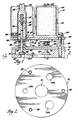
- an exhaust gas recirculation valve assembly l0 includes a base l2 having an inlet l4 for receiving exhaust gas from the engine.
- a cover l6 overlies base l2 to enclose an exhaust gas chamber l8, and base l2 has three calibrated outlets 20a, 20b, 20c each surrounded by a valve seat 22.
- a solenoid coil 24 is mounted on a bracket 26 over each valve seat 22.
- Each coil 24 surrounds an armature 28, and a valve stem 30 extends from each armature 28 to a valve member 32 disposed in chamber l8.
- a pair of seals 34 and 36 surround each valve stem 30.
- Each upper, or bracket seal 34 has a central disk portion 38 embracing valve stem 30 and a peripheral lip 40 biased by a spring 42 to engage bracket 26.
- Bracket seals 34 seal the openings 44 through bracket 26 about valve stems 30 and armatures 28.
- Each lower, cover seal 36 has a hub 46 embracing valve stem 30 and a peripheral flange portion 48 biased by spring 42 to engage cover l6.
- Cover seals 36 seal the openings 50 through cover l6 about valve stems 30.
- Seals 34 and 36 are formed of sintered graphite bronze, stainless steel, or other material selected to provide the desired lubricity and wear resistance.
- the bore 52 through the hub 46 of lower seal 36 may be chamfered at top and bottom to allow valve stem 30 to slide easily through seal 36. Chamfers are not required on the bore 54 through the thin central disk portion 38 of upper seal 34.
- valve assembly l0 To construct valve assembly l0, three solenoid coils 24 are secured on bracket 26 and the coil-bracket sub-assembly is inverted. Three armature-valve member-seal sub-assemblies 55 are made by placing lower seal 36, spring 42 and upper seal 34 on valve stem 30, placing armature 28 on valve stem 30, and upsetting tip 56 of valve stem 30 to secure the armature-valve member-seal sub-assembly. Springs 57 are inserted in each solenoid coil 24, and armatures 28 are then inserted through bracket openings 44 into solenoid coils 24. Cover l6 is secured to base l2 by fasteners 58, and the cover-base sub-assembly is inverted, assembled with valve members 32 extending through openings 50 to engage valve seats 22, and secured to bracket 26 with fasteners 60.
- each spring 57 biases the respective armature 28 and valve stem 30 to engage the respective valve member 32 with the associated valve seat 22.
- a solenoid coil 24 When a solenoid coil 24 is energized, the respective armature 28 and valve stem 30 are lifted against the bias of the respective spring 57 and the respective valve member 32 is raised away from the associated valve seat 22 to allow recirculation of exhaust gases.
- the areas of outlets 20a, 20b, 20c are calibrated as a binary series with the area of outlet 20b twice that of outlet 20a and the area of outlet 20c twice that of outlet 20b; in some applications, however, other combinations of outlet areas may be used.
- Recirculation of exhaust gases is metered by energizing the appropriate solenoid coil or coils 24 to raise the appropriate valve member or members 32 away from the associated valve seat or seats 22 and thus allow recirculation of exhaust gases through one or more of the calibrated outlets 20a, 20b, 20c.
- Each solenoid coil 24 has a pole piece 62 threaded into a yoke 64. Adjustment of pole piece 62 in yoke 64 determines the preload that the associated spring 57 exerts on the corresponding armature-valve stem-valve member, the air gap between the corresponding armature 20 and the respective pole piece 62 when the corresponding coil 24 is not energized, and the travel of the corresponding armature-valve stem-valve member when the corresponding coil 24 is energized.
- assembly l0 is shown here as having a circular base l2, it is clear that other configurations could be adopted within the space limitations of the particular engine application.
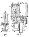
- an exhaust gas recirculation valve assembly ll0 includes a base ll2 having an inlet ll4 for receiving exhaust gas from the engine.
- a cover ll6 overlies base ll2 to enclose an exhaust gas chamber ll8, and base ll2 has three calibrated outlets l20 (only one being shown) each surrounded by a valve seat l22.
- a solenoid coil l24 is mounted on a bracket l26 over each valve seat l22.
- Each coil l24 surrounds an armature l28, and a valve stem l30 extends from each armature l28 to a valve member l32 disposed in chamber ll8.
- a pair of seals l34 and l36 surround each valve stem l30.
- Each upper, bracket seal l34 embraces valve stem l30 and is biased by a spring l42 to engage bracket l26.
- Bracket seals l34 seal openings l44 through bracket l26 about valve stems l30 and armatures l28.
- Each lower, cover seal l36 has a hub l46 embracing valve stem l30 and a peripheral flange portion l48 biased by spring l42 to engage cover ll6.
- Cover seals l36 seal openings l50 through cover ll6 about valve stems l30.
- Seals l34 and l36 are formed of sintered graphite bronze, stainless steel, or other material selected to provide the desired lubricity and wear resistance.
- the base ll2 of assembly ll0 has a discharge chamber l37 to route exhaust gases metered through outlets l20 to a common discharge opening l39.
- an exhaust gas recirculation valve assembly 2l0 includes a base 2l2 having an inlet 2l4 for receiving exhaust gas from the engine.
- a cover 2l6 overlies base 2l2 to enclose an exhaust gas chamber 2l8, and base 2l2 has three calibrated outlets 220 (only one being shown) each surrounded by a valve seat 222.
- a solenoid coil 224 is mounted on a bracket 226 over each valve seat 222.
- Each coil 224 surrounds an armature 228, and a valve stem 230 extends from each armature 228 to a valve member 232 disposed in chamber 2l8.
- a pair of seals 234 and 236 surround each valve stem 230.
- Each upper, bracket seal 234 has a central disk portion 238 embracing valve stem 230 and a peripheral lip 240 biased by a spring 242 to engage bracket 226.
- Bracket seals 234 seal openings 244 through bracket 226 about valve stems 230 and armatures 228.
- Each lower, cover seal 236 has a central disk portion 246 embracing valve stem 230 and a peripheral rim 248 biased by spring 242 to engage cover 2l6.
- Cover seals 236 seal openings 250 through cover 2l6 about valve stems 230.
- Seals 234 and 236 are formed of a material such as sintered graphite bronze selected to provide the desired lubricity and wear resistance.
- the central disk portion 246 of lower seal 236 scrapes valve stem 230 to prevent any accumulation of deposits on stem 230.
- valve assembly 2l0 To construct valve assembly 2l0, three solenoid coils 224 are secured on brackets 226, and three armature-valve member-seal sub-assemblies 255 are made by placing valve member 232, lower seal 236, spring seat 255a and return spring 255b, seal spring 242 and upper seal 234 on valve stem 230, placing armature 228 on valve stem 230, and upsetting tip 256 of valve stem 230 to secure the armature-valve member-seal sub-assembly.
- Armatures 228 are then inserted through bracket openings 244 into solenoid coils 224, the cover 2l6 and base 2l2 is assembled with valve members 232 extending through openings 250 to engage valve seats 222, and fasteners 260 are inserted through bracket 226 and cover 2l6 and threaded into base 2l2.
- Springs 242 react between the central disk portion 238 of upper seal 234 and the central disk portion 248 of lower seal 236 to engage seal 234 with bracket 226 and seal 236 with cover 2l6.
- each spring 255b biases the respective armature 228 and valve stem 230 to engage the corresponding valve member 232 with the associated valve seat 222.
- a solenoid coil 224 When a solenoid coil 224 is energized, the respective armature 228 and valve stem 230 are lifted against the bias of the corresponding spring 255b and the corresponding valve member 232 is raised away from the associated valve seat 222 to allow recirculation of exhaust gases.
- Each solenoid coil 224 has a pole piece 262 threaded into a yoke 264. Adjustment of pole piece 262 in yoke 264 determines the air gap and travel of the corresponding of its armature-valve stem-valve member. After adjusting pole piece 262 in yoke 264, yoke 264 is crimped laterally to prevent changes in the adjustment.
- Each valve member 232 swivels on a ball 266 formed at the end of the corresponding valve stem 230 to assure proper alignment of the valve member 232 on the corresponding valve seat 222.
- each orifice 220 has the narrowest opening at the top and a wider region 268 below. With this construction, any deposits that tend to accumulate in the orifice 220 would be pushed by the valve member 232 in the direction of flow through the orifice 220 into the wider region 268, thereby reducing the potential for any plugging of orifice 220.
- exhaust gas recirculation also could be metered with these assemblies by operating one or more solenoids as linear solenoids that vary the extent to which the respective valve member may be lifted away from the corresponding valve seat and thus vary the flow area between the valve member and the corresponding valve seat.
- one or more solenoids could be operated as pulse width-modulated or frequency-modulated solenoids that vary the time during which the respective valve member is lifted away from the corresponding valve seat and thus vary the flow past the valve member.
- a solenoid coil 24, l24, 224 might not be precisely aligned over a valve seat 22, l22, 222.
- the valve stem 30, l30, 230 is not constrained by a fixed seal in the cover opening 50, l50, 250.
- the armature-valve member-seal sub-assemblies 55, l55, 255 float laterally to compensate for potential misalignment of the solenoid coils 24, l24, 224 while still assuring that bracket openings 44, l44, 244 and cover openings 50, l50, 250 are sealed.
- central disk portions 246 of lower or cover seals 236 are slightly convex to assist in centering within openings 250 during assembly but still allow seals 236 to float laterally as indicated above.
Landscapes
- Engineering & Computer Science (AREA)
- Chemical & Material Sciences (AREA)
- Combustion & Propulsion (AREA)
- Mechanical Engineering (AREA)
- General Engineering & Computer Science (AREA)
- Magnetically Actuated Valves (AREA)
Applications Claiming Priority (4)
| Application Number | Priority Date | Filing Date | Title |
|---|---|---|---|
| US83380386A | 1986-02-28 | 1986-02-28 | |
| US833803 | 1986-02-28 | ||
| US06/918,359 US4725040A (en) | 1986-02-28 | 1986-10-14 | Exhaust gas recirculation valve assembly |
| US918359 | 1986-10-14 |
Publications (3)
| Publication Number | Publication Date |
|---|---|
| EP0234765A2 true EP0234765A2 (fr) | 1987-09-02 |
| EP0234765A3 EP0234765A3 (en) | 1988-01-13 |
| EP0234765B1 EP0234765B1 (fr) | 1990-02-07 |
Family
ID=27125658
Family Applications (1)
| Application Number | Title | Priority Date | Filing Date |
|---|---|---|---|
| EP19870300894 Expired - Lifetime EP0234765B1 (fr) | 1986-02-28 | 1987-02-02 | Vanne de recirculation des gaz d'échappement |
Country Status (7)
| Country | Link |
|---|---|
| US (1) | US4725040A (fr) |
| EP (1) | EP0234765B1 (fr) |
| KR (1) | KR900001391B1 (fr) |
| AU (1) | AU587681B2 (fr) |
| BR (1) | BR8700930A (fr) |
| CA (1) | CA1286559C (fr) |
| DE (1) | DE3761686D1 (fr) |
Cited By (8)
| Publication number | Priority date | Publication date | Assignee | Title |
|---|---|---|---|---|
| GB2207222A (en) * | 1987-07-20 | 1989-01-25 | Bosch Siemens Hausgeraete | Electromagnetic valve |
| FR2649465A1 (fr) * | 1989-07-06 | 1991-01-11 | Fichtel & Sachs Ag | Ensemble pour le passage de fluide |
| EP0428274A1 (fr) * | 1989-11-13 | 1991-05-22 | General Motors Corporation | Vanne de recirculation des gaz d'échappement |
| EP0461688A1 (fr) * | 1990-06-13 | 1991-12-18 | General Motors Corporation | Ensemble de soupape de recirculation de gaz d'échappement |
| US5180039A (en) * | 1989-07-06 | 1993-01-19 | Fichtel & Sachs Ag | Fluid passage unit |
| EP0816732A3 (fr) * | 1996-07-01 | 1998-04-15 | Firma Carl Freudenberg | Soupape électromagnétique |
| WO1999011921A1 (fr) * | 1997-09-03 | 1999-03-11 | Siemens Canada Limited | Soupape de recyclage des gaz d'echappement actionnee par un dispositif electromagnetique |
| ITBA20090039A1 (it) * | 2009-09-30 | 2011-04-01 | Ind Plants Consultants Srl | Valvola di regolazione industriale a tecnologia digitale. |
Families Citing this family (25)
| Publication number | Priority date | Publication date | Assignee | Title |
|---|---|---|---|---|
| US4997014A (en) * | 1989-09-14 | 1991-03-05 | Automatic Liquid Packaging, Inc. | Fill nozzle assembly |
| US5022431A (en) * | 1989-09-27 | 1991-06-11 | General Motors Corporation | Exhaust gas recirculation valve assembly |
| US5188073A (en) * | 1990-04-06 | 1993-02-23 | Hitachi Ltd. | Fluid control valve, valve support member therefor and idling air amount control apparatus for automobile using the fluid control valve |
| US5129623A (en) * | 1991-12-06 | 1992-07-14 | General Motors Corporation | Linear EGR tri-bearing |
| US5238224A (en) * | 1992-08-20 | 1993-08-24 | Siemens Automotive L.P. | Dry coil |
| US5289811A (en) * | 1993-05-10 | 1994-03-01 | General Motors Corporation | Purge control device |
| US5605318A (en) * | 1994-04-14 | 1997-02-25 | Eaton Corporation | Electric expansion valve |
| JP3479353B2 (ja) * | 1994-10-17 | 2003-12-15 | 株式会社ケーヒン | 排気ガス再循環バルブ |
| US5626327A (en) * | 1995-04-27 | 1997-05-06 | Borg-Warner Automotive, Inc. | Solenoid-driven valve having a roller bearing |
| JP3683643B2 (ja) * | 1996-05-09 | 2005-08-17 | 矢崎総業株式会社 | ソレノイドユニット |
| EP1155421A1 (fr) * | 1999-02-22 | 2001-11-21 | Mannesmann Rexroth GmbH | Electro-aimant et soupape hydraulique dotee d'un tel electro-aimant |
| US6382587B1 (en) | 1999-05-17 | 2002-05-07 | Bld Products, Ltd. | Fluid control valve |
| US6497226B2 (en) * | 2000-02-18 | 2002-12-24 | Delphi Technologies, Inc. | Modular, compliant, sealing bearing assembly |
| US6467754B2 (en) * | 2000-02-24 | 2002-10-22 | Delphi Technologies, Inc. | Adaptable gas and moisture shield for a gas management valve |
| US6604542B1 (en) | 2000-02-24 | 2003-08-12 | Delphi Technologies, Inc. | Modular exhaust gas recirculation valve |
| US6453934B1 (en) * | 2001-02-07 | 2002-09-24 | Delphi Technologies, Inc. | Shaft brush for preventing coking in a gas management valve |
| DE10108043B4 (de) * | 2001-02-20 | 2005-09-01 | Robert Bosch Gmbh | Selbstreinigende Ventile im Zuluft- oder Abgassystem bei Verbrennungskraftmaschinen |
| US7104523B2 (en) * | 2004-06-12 | 2006-09-12 | Borgwarner Inc. | Valve having contamination counter-measures |
| KR20070108948A (ko) | 2005-03-08 | 2007-11-13 | 보르그워너 인코퍼레이티드 | 대기 위치를 갖는 egr 밸브 |
| US7886387B2 (en) * | 2007-01-26 | 2011-02-15 | Rapid Air Llc | Multiple configuration air mattress pump system |
| US20110265898A1 (en) * | 2007-01-26 | 2011-11-03 | Rapid Air Llc (A Wisconsin Limited Liability Company) | Sealed Manifold For Air Pump System |
| US7743757B2 (en) * | 2007-07-19 | 2010-06-29 | Ford Global Technologies, Llc | System and method for exhaust gas recirculation |
| KR101233477B1 (ko) * | 2008-08-13 | 2013-02-14 | 미쓰비시덴키 가부시키가이샤 | 배기 가스 순환 밸브 장치 |
| US9645585B2 (en) * | 2009-01-15 | 2017-05-09 | Robertshaw Controls Company | Variable flow digital gas valve |
| CA2966857C (fr) | 2014-11-07 | 2021-02-23 | Swagelok Company | Joint de soupape a alignement automatique |
Family Cites Families (20)
| Publication number | Priority date | Publication date | Assignee | Title |
|---|---|---|---|---|
| US2889904A (en) * | 1956-08-24 | 1959-06-09 | Martinoli Sante Tino | Apparatus for increasing efficiency of internal combustion engines |
| US2929405A (en) * | 1957-07-09 | 1960-03-22 | Leslie W Beebe | Pedal actuated mixing valve |
| AT233326B (de) * | 1962-07-12 | 1964-05-11 | Michael Guillermo Dipl Ing May | Verfahren und Einrichtung zur Verminderung der Anteile der unverbrannten und teilverbrannten Bestandteile in den Abgasen von fremdgezündeten Viertakt-Verbrennungskraftmaschinen |
| US3520312A (en) * | 1968-04-19 | 1970-07-14 | Gen Motors Corp | Flow process including viscosity control |
| GB1270516A (en) * | 1969-01-20 | 1972-04-12 | Nissan Motor | Induction system for motor vehicles |
| US3625474A (en) * | 1969-11-21 | 1971-12-07 | Julius R Juede | Solenoid-actuated high-temperature fluid valves |
| US3980063A (en) * | 1970-06-12 | 1976-09-14 | Regie Nationale Des Usines Renault | Devices for recirculating exhaust gases in internal combustion engines |
| DE2105583A1 (de) * | 1971-02-06 | 1972-08-10 | Robert Bosch Gmbh, 7000 Stuttgart | Magnetventil zur Abgasrückführung bei Brennkraftmaschinen |
| DE2137694A1 (de) * | 1971-07-28 | 1973-02-08 | Bosch Gmbh Robert | Magnetventil zur abgasrueckfuehrung bei brennkraftmaschinen |
| US3762384A (en) * | 1972-01-24 | 1973-10-02 | Gen Motors Corp | Exhaust gas recirculation valve |
| US3799133A (en) * | 1972-06-22 | 1974-03-26 | Gen Motors Corp | Solenoid valve control for exhaust gas recirculation |
| JPS5122990Y2 (fr) * | 1972-09-26 | 1976-06-14 | ||
| JPS529472Y2 (fr) * | 1972-09-30 | 1977-02-28 | ||
| US3901202A (en) * | 1973-05-25 | 1975-08-26 | Gen Motors Corp | Vacuum bias regulator assembly |
| DE2504443C3 (de) * | 1975-02-04 | 1978-06-29 | Danfoss A/S, Nordborg (Daenemark) | Ventil mit Spreizmanschetten-Dichtung |
| JPS52102929A (en) * | 1976-02-24 | 1977-08-29 | Toyota Motor Corp | Exhaust-gas-circulation control valve system for automobile |
| US4100234A (en) * | 1977-02-11 | 1978-07-11 | Acf Industries, Inc. | Air metering apparatus |
| DE2815849C2 (de) * | 1978-04-12 | 1984-08-23 | Linde Ag, 6200 Wiesbaden | Elektromagnetisch betätigte Gaswechselventile für Kolbenmaschinen |
| DE3048308C2 (de) * | 1980-12-20 | 1986-02-13 | Theodor Heimeier Metallwerk Gmbh, 4782 Erwitte | Heizungsventil |
| AU3248784A (en) * | 1983-09-28 | 1985-04-04 | Canadian Fram Limited | Electromechanically controlled egr valve and method |
-
1986
- 1986-10-14 US US06/918,359 patent/US4725040A/en not_active Expired - Lifetime
-
1987
- 1987-02-02 DE DE8787300894T patent/DE3761686D1/de not_active Expired - Lifetime
- 1987-02-02 EP EP19870300894 patent/EP0234765B1/fr not_active Expired - Lifetime
- 1987-02-04 CA CA 528933 patent/CA1286559C/fr not_active Expired - Lifetime
- 1987-02-13 AU AU68763/87A patent/AU587681B2/en not_active Ceased
- 1987-02-23 KR KR1019870001525A patent/KR900001391B1/ko not_active Expired
- 1987-02-26 BR BR8700930A patent/BR8700930A/pt not_active IP Right Cessation
Cited By (10)
| Publication number | Priority date | Publication date | Assignee | Title |
|---|---|---|---|---|
| GB2207222A (en) * | 1987-07-20 | 1989-01-25 | Bosch Siemens Hausgeraete | Electromagnetic valve |
| FR2649465A1 (fr) * | 1989-07-06 | 1991-01-11 | Fichtel & Sachs Ag | Ensemble pour le passage de fluide |
| GB2234041A (en) * | 1989-07-06 | 1991-01-23 | Fichtel & Sachs Ag | An electro-magnetically operated valve for a fluid damper |
| US5180039A (en) * | 1989-07-06 | 1993-01-19 | Fichtel & Sachs Ag | Fluid passage unit |
| GB2234041B (en) * | 1989-07-06 | 1993-04-21 | Fichtel & Sachs Ag | A fluid passage means |
| EP0428274A1 (fr) * | 1989-11-13 | 1991-05-22 | General Motors Corporation | Vanne de recirculation des gaz d'échappement |
| EP0461688A1 (fr) * | 1990-06-13 | 1991-12-18 | General Motors Corporation | Ensemble de soupape de recirculation de gaz d'échappement |
| EP0816732A3 (fr) * | 1996-07-01 | 1998-04-15 | Firma Carl Freudenberg | Soupape électromagnétique |
| WO1999011921A1 (fr) * | 1997-09-03 | 1999-03-11 | Siemens Canada Limited | Soupape de recyclage des gaz d'echappement actionnee par un dispositif electromagnetique |
| ITBA20090039A1 (it) * | 2009-09-30 | 2011-04-01 | Ind Plants Consultants Srl | Valvola di regolazione industriale a tecnologia digitale. |
Also Published As
| Publication number | Publication date |
|---|---|
| AU587681B2 (en) | 1989-08-24 |
| EP0234765B1 (fr) | 1990-02-07 |
| CA1286559C (fr) | 1991-07-23 |
| KR870008101A (ko) | 1987-09-24 |
| AU6876387A (en) | 1987-09-03 |
| US4725040A (en) | 1988-02-16 |
| DE3761686D1 (de) | 1990-03-15 |
| EP0234765A3 (en) | 1988-01-13 |
| BR8700930A (pt) | 1987-12-22 |
| KR900001391B1 (ko) | 1990-03-09 |
Similar Documents
| Publication | Publication Date | Title |
|---|---|---|
| EP0234765A2 (fr) | Vanne de recirculation des gaz d'échappement | |
| EP0701055B1 (fr) | Actionneur pour soupape de recirculation de gaz d'échappement | |
| DE60002627T2 (de) | Elektromagnetisch betätigtes Abgasrückführungsventil | |
| AU616231B2 (en) | Pico fuel injector valve | |
| EP0717186B1 (fr) | Clapet électromagnétique à faible bruit | |
| EP0701054A2 (fr) | Actionneur à déplacement linéaire à solenoide pour une soupape de recirculations de gaz d'échappement | |
| EP0565292A1 (fr) | Soupape proportionnelle commandé par solénoide | |
| CN102720878A (zh) | 电磁操纵流体控制阀 | |
| WO1998008014A1 (fr) | Soupape d'injection de carburant et moteur equipe de cette soupape | |
| US5626327A (en) | Solenoid-driven valve having a roller bearing | |
| US6886597B2 (en) | Proportional electrovalve for motor cooling liquid circuit | |
| JP2020529570A (ja) | ガス状媒体を制御するための比例弁 | |
| CA1314784C (fr) | Robinet electromagnetique de commande, a haute pression equilibree et a reponse instantanee | |
| KR960010293B1 (ko) | 경사아마츄어를 구비한 전자식 연료분사기 | |
| US6851657B2 (en) | High pressure gaseous fuel solenoid valve | |
| EP0480609A1 (fr) | Injecteur de combustible pour moteur à combustion interne | |
| EP1300578B1 (fr) | Soupape de commande des émissions et actionnée électromagnétiquement ayant un pièce de pôle biconique | |
| EP1300577B1 (fr) | Soupape EGR linéaire et électrique ayant un amortisseur de mouvement | |
| US6123275A (en) | Dual gap fuel injector | |
| AU737153B2 (en) | Electrically actuated reed valve | |
| US6910466B2 (en) | Elastomeric vapor flow control actuator with improved mechanical advantage | |
| EP0160120B1 (fr) | Vanne à commande électromagnétique | |
| EP3467299A1 (fr) | Ensemble de soupape pour soupape d'injection et soupape d'injection | |
| EP1752625A1 (fr) | Soupape à commande électromagnétique | |
| JPH07145873A (ja) | 電磁弁 |
Legal Events
| Date | Code | Title | Description |
|---|---|---|---|
| PUAI | Public reference made under article 153(3) epc to a published international application that has entered the european phase |
Free format text: ORIGINAL CODE: 0009012 |
|
| 17P | Request for examination filed |
Effective date: 19870209 |
|
| AK | Designated contracting states |
Kind code of ref document: A2 Designated state(s): DE FR GB IT SE |
|
| PUAL | Search report despatched |
Free format text: ORIGINAL CODE: 0009013 |
|
| AK | Designated contracting states |
Kind code of ref document: A3 Designated state(s): DE FR GB IT SE |
|
| 17Q | First examination report despatched |
Effective date: 19890623 |
|
| ITF | It: translation for a ep patent filed | ||
| GRAA | (expected) grant |
Free format text: ORIGINAL CODE: 0009210 |
|
| AK | Designated contracting states |
Kind code of ref document: B1 Designated state(s): DE FR GB IT SE |
|
| REF | Corresponds to: |
Ref document number: 3761686 Country of ref document: DE Date of ref document: 19900315 |
|
| ET | Fr: translation filed | ||
| PLBE | No opposition filed within time limit |
Free format text: ORIGINAL CODE: 0009261 |
|
| STAA | Information on the status of an ep patent application or granted ep patent |
Free format text: STATUS: NO OPPOSITION FILED WITHIN TIME LIMIT |
|
| 26N | No opposition filed | ||
| PGFP | Annual fee paid to national office [announced via postgrant information from national office to epo] |
Ref country code: GB Payment date: 19940131 Year of fee payment: 8 |
|
| PGFP | Annual fee paid to national office [announced via postgrant information from national office to epo] |
Ref country code: SE Payment date: 19940222 Year of fee payment: 8 |
|
| PGFP | Annual fee paid to national office [announced via postgrant information from national office to epo] |
Ref country code: FR Payment date: 19940225 Year of fee payment: 8 |
|
| ITTA | It: last paid annual fee | ||
| EAL | Se: european patent in force in sweden |
Ref document number: 87300894.0 |
|
| PG25 | Lapsed in a contracting state [announced via postgrant information from national office to epo] |
Ref country code: GB Effective date: 19950202 |
|
| PG25 | Lapsed in a contracting state [announced via postgrant information from national office to epo] |
Ref country code: SE Effective date: 19950203 |
|
| GBPC | Gb: european patent ceased through non-payment of renewal fee |
Effective date: 19950202 |
|
| PG25 | Lapsed in a contracting state [announced via postgrant information from national office to epo] |
Ref country code: FR Effective date: 19951031 |
|
| EUG | Se: european patent has lapsed |
Ref document number: 87300894.0 |
|
| REG | Reference to a national code |
Ref country code: FR Ref legal event code: ST |
|
| PG25 | Lapsed in a contracting state [announced via postgrant information from national office to epo] |
Ref country code: IT Free format text: LAPSE BECAUSE OF NON-PAYMENT OF DUE FEES;WARNING: LAPSES OF ITALIAN PATENTS WITH EFFECTIVE DATE BEFORE 2007 MAY HAVE OCCURRED AT ANY TIME BEFORE 2007. THE CORRECT EFFECTIVE DATE MAY BE DIFFERENT FROM THE ONE RECORDED. Effective date: 20050202 |
|
| PGFP | Annual fee paid to national office [announced via postgrant information from national office to epo] |
Ref country code: DE Payment date: 20060126 Year of fee payment: 20 |