EP0235404A2 - Verfahren und Vorrichtung zur Bestimmung der räumlichen Verteilung eines Gases - Google Patents
Verfahren und Vorrichtung zur Bestimmung der räumlichen Verteilung eines Gases Download PDFInfo
- Publication number
- EP0235404A2 EP0235404A2 EP86202126A EP86202126A EP0235404A2 EP 0235404 A2 EP0235404 A2 EP 0235404A2 EP 86202126 A EP86202126 A EP 86202126A EP 86202126 A EP86202126 A EP 86202126A EP 0235404 A2 EP0235404 A2 EP 0235404A2
- Authority
- EP
- European Patent Office
- Prior art keywords
- mirror
- gas
- detector
- filter
- absorption band
- Prior art date
- Legal status (The legal status is an assumption and is not a legal conclusion. Google has not performed a legal analysis and makes no representation as to the accuracy of the status listed.)
- Granted
Links
- 238000000034 method Methods 0.000 title description 5
- 239000007789 gas Substances 0.000 claims abstract description 66
- 230000005855 radiation Effects 0.000 claims abstract description 46
- 238000010521 absorption reaction Methods 0.000 claims abstract description 44
- 238000005259 measurement Methods 0.000 claims abstract description 27
- 230000003595 spectral effect Effects 0.000 claims abstract description 11
- IJGRMHOSHXDMSA-UHFFFAOYSA-N Atomic nitrogen Chemical compound N#N IJGRMHOSHXDMSA-UHFFFAOYSA-N 0.000 claims description 6
- 230000005540 biological transmission Effects 0.000 claims description 5
- 239000000463 material Substances 0.000 claims description 5
- 229910052757 nitrogen Inorganic materials 0.000 claims description 3
- 239000004065 semiconductor Substances 0.000 claims description 3
- 230000015572 biosynthetic process Effects 0.000 claims description 2
- 239000007788 liquid Substances 0.000 claims description 2
- 230000001360 synchronised effect Effects 0.000 claims description 2
- 238000003384 imaging method Methods 0.000 claims 2
- 230000007246 mechanism Effects 0.000 description 7
- 238000004847 absorption spectroscopy Methods 0.000 description 4
- VNWKTOKETHGBQD-UHFFFAOYSA-N methane Chemical compound C VNWKTOKETHGBQD-UHFFFAOYSA-N 0.000 description 4
- UHOVQNZJYSORNB-UHFFFAOYSA-N Benzene Chemical compound C1=CC=CC=C1 UHOVQNZJYSORNB-UHFFFAOYSA-N 0.000 description 3
- MWUXSHHQAYIFBG-UHFFFAOYSA-N nitrogen oxide Inorganic materials O=[N] MWUXSHHQAYIFBG-UHFFFAOYSA-N 0.000 description 3
- 238000001228 spectrum Methods 0.000 description 3
- QGZKDVFQNNGYKY-UHFFFAOYSA-N Ammonia Chemical compound N QGZKDVFQNNGYKY-UHFFFAOYSA-N 0.000 description 2
- RAHZWNYVWXNFOC-UHFFFAOYSA-N Sulphur dioxide Chemical compound O=S=O RAHZWNYVWXNFOC-UHFFFAOYSA-N 0.000 description 2
- XAGFODPZIPBFFR-UHFFFAOYSA-N aluminium Chemical compound [Al] XAGFODPZIPBFFR-UHFFFAOYSA-N 0.000 description 2
- 229910052782 aluminium Inorganic materials 0.000 description 2
- 239000004411 aluminium Substances 0.000 description 2
- 230000000694 effects Effects 0.000 description 2
- 230000003534 oscillatory effect Effects 0.000 description 2
- 230000008569 process Effects 0.000 description 2
- 239000000700 radioactive tracer Substances 0.000 description 2
- VZGDMQKNWNREIO-UHFFFAOYSA-N tetrachloromethane Chemical compound ClC(Cl)(Cl)Cl VZGDMQKNWNREIO-UHFFFAOYSA-N 0.000 description 2
- UGFAIRIUMAVXCW-UHFFFAOYSA-N Carbon monoxide Chemical compound [O+]#[C-] UGFAIRIUMAVXCW-UHFFFAOYSA-N 0.000 description 1
- RWSOTUBLDIXVET-UHFFFAOYSA-N Dihydrogen sulfide Chemical compound S RWSOTUBLDIXVET-UHFFFAOYSA-N 0.000 description 1
- VGGSQFUCUMXWEO-UHFFFAOYSA-N Ethene Chemical compound C=C VGGSQFUCUMXWEO-UHFFFAOYSA-N 0.000 description 1
- 239000005977 Ethylene Substances 0.000 description 1
- 238000004566 IR spectroscopy Methods 0.000 description 1
- XSTXAVWGXDQKEL-UHFFFAOYSA-N Trichloroethylene Chemical group ClC=C(Cl)Cl XSTXAVWGXDQKEL-UHFFFAOYSA-N 0.000 description 1
- 229910021529 ammonia Inorganic materials 0.000 description 1
- 230000003321 amplification Effects 0.000 description 1
- 230000002238 attenuated effect Effects 0.000 description 1
- 229910002091 carbon monoxide Inorganic materials 0.000 description 1
- 230000008859 change Effects 0.000 description 1
- 210000000078 claw Anatomy 0.000 description 1
- 239000000567 combustion gas Substances 0.000 description 1
- 238000010276 construction Methods 0.000 description 1
- 230000001419 dependent effect Effects 0.000 description 1
- 238000001514 detection method Methods 0.000 description 1
- 230000002349 favourable effect Effects 0.000 description 1
- 229910052732 germanium Inorganic materials 0.000 description 1
- GNPVGFCGXDBREM-UHFFFAOYSA-N germanium atom Chemical compound [Ge] GNPVGFCGXDBREM-UHFFFAOYSA-N 0.000 description 1
- 230000002452 interceptive effect Effects 0.000 description 1
- 238000012986 modification Methods 0.000 description 1
- 230000004048 modification Effects 0.000 description 1
- 238000003199 nucleic acid amplification method Methods 0.000 description 1
- 230000003287 optical effect Effects 0.000 description 1
- 230000035945 sensitivity Effects 0.000 description 1
- 239000007787 solid Substances 0.000 description 1
- 235000010269 sulphur dioxide Nutrition 0.000 description 1
- 239000004291 sulphur dioxide Substances 0.000 description 1
- UBOXGVDOUJQMTN-UHFFFAOYSA-N trichloroethylene Natural products ClCC(Cl)Cl UBOXGVDOUJQMTN-UHFFFAOYSA-N 0.000 description 1
- 238000009423 ventilation Methods 0.000 description 1
- 238000012800 visualization Methods 0.000 description 1
Images



Classifications
-
- G—PHYSICS
- G01—MEASURING; TESTING
- G01N—INVESTIGATING OR ANALYSING MATERIALS BY DETERMINING THEIR CHEMICAL OR PHYSICAL PROPERTIES
- G01N21/00—Investigating or analysing materials by the use of optical means, i.e. using sub-millimetre waves, infrared, visible or ultraviolet light
- G01N21/17—Systems in which incident light is modified in accordance with the properties of the material investigated
- G01N21/25—Colour; Spectral properties, i.e. comparison of effect of material on the light at two or more different wavelengths or wavelength bands
- G01N21/31—Investigating relative effect of material at wavelengths characteristic of specific elements or molecules, e.g. atomic absorption spectrometry
- G01N21/35—Investigating relative effect of material at wavelengths characteristic of specific elements or molecules, e.g. atomic absorption spectrometry using infrared light
- G01N21/3504—Investigating relative effect of material at wavelengths characteristic of specific elements or molecules, e.g. atomic absorption spectrometry using infrared light for analysing gases, e.g. multi-gas analysis
-
- G—PHYSICS
- G01—MEASURING; TESTING
- G01J—MEASUREMENT OF INTENSITY, VELOCITY, SPECTRAL CONTENT, POLARISATION, PHASE OR PULSE CHARACTERISTICS OF INFRARED, VISIBLE OR ULTRAVIOLET LIGHT; COLORIMETRY; RADIATION PYROMETRY
- G01J3/00—Spectrometry; Spectrophotometry; Monochromators; Measuring colours
- G01J3/12—Generating the spectrum; Monochromators
- G01J2003/1226—Interference filters
- G01J2003/1234—Continuously variable IF [CVIF]; Wedge type
-
- G—PHYSICS
- G01—MEASURING; TESTING
- G01N—INVESTIGATING OR ANALYSING MATERIALS BY DETERMINING THEIR CHEMICAL OR PHYSICAL PROPERTIES
- G01N21/00—Investigating or analysing materials by the use of optical means, i.e. using sub-millimetre waves, infrared, visible or ultraviolet light
- G01N21/17—Systems in which incident light is modified in accordance with the properties of the material investigated
- G01N2021/1793—Remote sensing
- G01N2021/1795—Atmospheric mapping of gases
-
- G—PHYSICS
- G01—MEASURING; TESTING
- G01N—INVESTIGATING OR ANALYSING MATERIALS BY DETERMINING THEIR CHEMICAL OR PHYSICAL PROPERTIES
- G01N21/00—Investigating or analysing materials by the use of optical means, i.e. using sub-millimetre waves, infrared, visible or ultraviolet light
- G01N21/17—Systems in which incident light is modified in accordance with the properties of the material investigated
- G01N21/25—Colour; Spectral properties, i.e. comparison of effect of material on the light at two or more different wavelengths or wavelength bands
- G01N21/31—Investigating relative effect of material at wavelengths characteristic of specific elements or molecules, e.g. atomic absorption spectrometry
- G01N21/314—Investigating relative effect of material at wavelengths characteristic of specific elements or molecules, e.g. atomic absorption spectrometry with comparison of measurements at specific and non-specific wavelengths
Definitions
- the invention relates to a gas measuring system comprising an infrared radiation source, a back reflector situated at a distance from said source, a receiver situated near the source, a detector, first focusing means for the formation of an image of a part of the back reflector and a narrow-band spectral filter.
- Such a system is known from US-A-3,925,666 and said system is designed to, and suitable for, detecting the presence of a specific harmful gas and determining the quantity of said gas and the position of the gas Leak.
- the radiation source is an infrared Laser with a very narrow spectral band (width Less than 1 A (10-10 meter)), so that the system can be used only for detecting a certain gas, in particular hydrogen sulphide.
- a certain gas in particular hydrogen sulphide.
- Another disadvantage of the known gas detector system is that it cannot provide a two-dimensional image of the distribution of the gas concerned in the space at a certain instant in time. In order to obtain adequate information rapidly about the distribution of the gas (to estimate the size of a gas leak) and the movement of a gas cloud (to estimate the human exposure) in a space, two-dimensional images of the gas distribution are in fact necessary at certain instants in time.
- the object of the invention is to provide a system defined in the introduction which does not have the said drawbacks, which consequently has a very general field of application, which can produce images of the distribution of the gas in the space (for example, on a display screen), and with which the quantity of gas in a certain part of the space can be measured.
- the gas measuring system which is defined in the introduction is characterized for the purpose in that the infrared radiation source is a thermal radiator, that the back reflector comprises a screen of reLativeLy large surface, the front face of which is constructed from a Large number of faces covered with opaque reflection material or formed therefrom and intersecting each other at an angle, that said spectral filter is installed at the position where said first focusing means form an image and that second focusing means are present for focusing the radiation which has passed through the filter on the input of the detector, that the spectral filter is adjustable in a manner such that measurements can be made consecutively in the absorption band of the gas concerned and outside the absorption band, and that a signal processor is added to the system, which processor is provided with an anaLogue/digitaL converter for converting voltage signals originating from the detector into numbers, computing means for dividing every number which corresponds to the radiation intensity measured in the absorption band concerned by a number which corresponds to the radiation intensity measured outside the absorption band concerned (differential absorption spect
- the thermal radiator provides infrared radiation with wavelengths between 2.5 ⁇ m and 14.5 ⁇ m (1 ⁇ m is 10 -6 m) and can therefore be used for detecting very many gases by means of differential infrared absorption spectrometry.
- the screen is necessary in order to reflect radiation from the thermal radiator over a Large area back to the input of the scanner which is situated near the radiator.
- the first focusing means an intermediate image of a part of the reflector screen can be formed on the filter.
- said intermediate image has an area dimension of approx. 1 mm 2 .
- the filter has the properties of a narrow-band spectral filter.
- An image of the said part of the reflector screen must, of course, be formed on the detector.
- This purpose is served by the second focusing means which operate in a manner such that the field of view of the detector, which is Limited by a diaphragm, will be fiLLed entirely with radiation.
- the spectral filter is consecutively adjusted in a manner such that the narrow wavelength band of the radiation transmitted corresponds to an undisturbed absorption band of the gas to be measured and corresponds to a wavelength band where none of the gases present absorbs.
- the receiver is preferably provided with scanning mirrors with which scanning can be carried out in the horizontal direction over, for example, 30° and in the vertical direction over, for example, 10°.
- the possibility is not ruled out of using, instead of a scanning mechanism with rotating mirrors and/or oscillating mirrors, an array of detectors, a set of gas-specific interference filters being employed.
- a back-reflecting screen for infrared radiation is known per se from US-A-4,082,414.
- the mirror for carrying out a horizontal scan consists, for example, of a mirror rotor in the form of a pyramid with at Least three side faces.
- the vertical scan use is made, for example, of an oscillating mirror, the drive of which is synchronized with respect to the drive of the mirror rotor.
- the synchronization between mirror rotor and oscillating mirror could be carried out completely electronically, but the drive of the oscillating mirror can also be coupled mechanically to the drive motor of the mirror rotor.
- the filter may consist of a rotatable disc on which filter segments in the shape of a circular arc are mounted, the peak transmission wavelength varying with the angle.
- the narrow wavelength range of the transmitted radiation can be adjusted by rotating (for example, with a stepping motor) the filter wheel which functions as a monochromator.
- the filter wheel which functions as a monochromator.
- a small adjusted section of a chosen segment is used to produce the intermediate image thereon.
- the wavelength of said section essentially corresponds to the wavelength of an absorption band of the gas to be scanned. VirtuaLLy all the gases encountered in practice have absorption bands in the infrared part of the electromagnetic spectrum (1-20 um).
- a semiconductor detector cooled with liquid nitrogen is to be preferred. However, other detectors are not out of the question.
- Figure 1a shows a diagrammatic view in perspective of the gas cloud scanner according to the invention with radiator and back-reflecting screen.
- Figure 1b shows a variant of the embodiment of the screen.
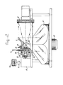
- Figure 2 shows a side view of the receiver.
- Figure 3 shows a plan view of the receiver.
- Figure 4 shows a cross-section
- the diagrammatic Figure 1 shows an infrared radiator 1 which irradiates a back-reflecting screen 2 situated at a distance.
- the radiator is situated near a receiver 3 which scans the space between radiator and screen both in the horizontal and in the vertical direction and images the reflected Light on a filter which filters out the frequencies of the infrared radiation with the exception of the frequency range to be absorbed by a gas cloud.
- the infrared absorption caused by any gas cloud present is determined with a detector.
- a "photo" of the gas cloud is obtained on the basis of said measurements by means of an amplifier and computer.
- the back-reflecting screen is provided with a Large number of smaller cube corners 4 which are placed directly next to each other in a manner such that the vertex 5 is recessed furthest to the rear.
- the cube corners and the rear wall, to which the cube corners are joined, are manufactured from plastic material, a reflecting aluminium Layer having been vapour-deposited on the cube faces which point forwards.
- the direction of a ray incident on the screen is changed three times by reflection and returns in a direction which is essentially parallel to the incident direction. Because the cube corners 4 are recessed and the front faces are provided with a reflecting Layer, the infrared radiation originating from the radiator 1 is virtually not absorbed in the plastic material of the screen.
- the back reflector according to the invention has a small scattering of the returning beam and the back-reflecting principLe operates weLL: the reflected radiation falls within a circle having a small diameter around the source.
- the maximum differences in the reflection properties are approximately 20%. The effect of said differences on the final result is eliminated by use of the differential absorption method described.
- Figure 1b shows an embodiment of the cube corners which differs somewhat from the embodiment according to Figure 1a.
- the infrared radiation passes through a gas cloud, a certain frequency band of the spectrum will be absorbed.
- a radiation beam is obtained, the frequency of which corresponds to the absorption frequency of the gas cloud possibly present.
- the intensity of the radiation is measured by the detector.
- a second measurement is carried out in a frequency range which is situated next to the absorption range and both measurements are divided by each other.
- Such a differential absorption method is carried out by means of a scanning mechanism, to be described in more detail, in the solid angle between the receiver and the screen, the measurements being processed into a "photo" after amplification in a computer.
- Said photo is a two-dimensional image of the distribution of a harmful gas or vapour in the space.
- a complete scan is carried out, for example, within 1 second.
- the receiver shown in Figures 2 to 4 incl. comprises a rotatable mirror 6 in the form of a truncated 4-sided pyramid, an oscillating mirror 7, a focusing mirror 8, a filter disc 9, a detector, and a signal processor 11 with display screen 11a.
- the pyramidal mirror 6, which is intended for the horizontal scanning of the space, is driven by a motor 12.
- the driven motor spindle 13 is also used to drive the oscillating mirror 7 via a transmission system.
- Said transmission system comprises a worm 14 mounted on the motor spindle, a worm wheel 15 which is in mesh therewith and which is mounted on a spindle 16 which carries an eccentrically situated cam disc 17 at its end.
- a cam wheel 18 is pressed against the said cam disc 17 by means of a spring 19 which extends between a frame part 21 and an arm 22 which is attached to the rear side of the oscillating mirror 7.
- a claw clutch 20 In the spindle there is mounted a claw clutch 20 by means of which the drive of the oscillating mirror can be switched over to manual operation.
- the oscillating mirror 7 is mounted with respect to the frame by means of bearings 23. It will be clear that, when spindle 13 is rotating, not only the pyramidal mirror 6 is rotated, but the mirror 7 also undergoes an oscillatory movement. This oscillatory movement is produced because the cam wheel 15 moves up and down during its movement along the eccentric disc 17. The movement is always uniform (no sinusoidaL movement).
- the infrared radiation reflected by the screen 2 strikes the rotating mirror 3 which reflects the radiation onto the oscillating mirror 7 which reflects the radiation onto the concave focusing mirror 6 which forms an image of the relevant part of the screen 2 on the filter disc 9.
- a germanium Lens 24 which also forms an image of the relevant part of the screen 2 on the detector and ensures that the beam fiLLs the opening of the detector.
- the filter disc is brought by a computer-controLLed stepping motor 25 consecutively into the position in which the radiation of the absorption frequency of the harmful gas possibly present and radiation of an absorption range situated next to it are transmitted.
- the consecutive measurements resulting therefrom are necessary in order to be able to carry out the differential absorption measurement described above and thereby to be able to suppress the effect of information which is independent of the wavelength and the Like.
- the detector converts the radiation received into electrical voltage signals which are processed in the manner indicated above by means of the signal processor 11 to form a two-dimensional image (photo) of the gas cloud on the display screen 11a.
- An image scan is obtained within 1 second and the computer processes the measurement data into a photo within 1 minute.
- Said processor 11 comprises an anaLogue/digitaL converter which converts the voltage signals into numbers, and computing means for dividing every number which corresponds to the radiation intensity measured in the absorption band of the gas by a number which corresponds to the radiation intensity outside the absorption band.
- these quotients are converted into grey-value LeveLs or colour LeveLs which form the desired image on the display screen 11a.
- the measurement is based on the knowledge that the intensity of the absorption is a measure of the quantity of harmful gas in the path of the infrared radiation. This dependency is governed by the Lambert-Beer Law:
- the measurement in the absorption band concerned and the measurement outside the band can also be carried out at the same time instead of consecutively. A second detector is then necessary.
- the filter disc 9 consists of a rotatable disc which is provided, for exampLe, with three filter segments, viz. a filter segment with a transmitted wavelength range of 2.5 - 4.5 ⁇ m, a filter segment with a transmitted wavelength range of 4.5 - 8.0 ⁇ m and a segment with a transmitted wavelength range of 7.9 - 14.5 ⁇ m.
- the detector 10 is preferably a semiconductor detector which has a favourable signaL/noise ratio and a high sensitivity. However, this type of detector has to be cooled with nitrogen.
- the scanning mechanism could be dispensed with if use is made of an array of detectors, the image having as many pixels as there are detectors in the array.
- a single detector combined with a scanning mechanism is preferable, scanning being carried out horizontally over 30° and vertically over 10°. This preference might change in the future.
- the scanning mechanism scans the image Line by Line.
- the beam is incident on the faces of the pyramidal scan rotor 6 at an angle of 45° with respect to the axis of symmetry and is reflected paraLLeL to the said axis.
- a horizontal scanning angle of 30° corresponds to a rotational angle of 30° of the rotor.
- Both the mirror rotor 6 and the osciLLating mirror 7 are preferably manufactured from aluminium.
- the gas cloud scanner in fact measures the quantity of gas in the radiation path and not the gas concentration. However, the average gas concentration can be calculated after calibration.
- an infrared radiator and a back-reflecting screen are situated at a distance from each other and that the reflected infrared radiation is picked up in a receiver near the radiator, the absorption of infrared radiation caused by any gas cloud present being measured and the differential measurement results being processed by a signal processor into a two-dimensional image of the cloud.
- the construction of the infrared back-reflecting screen is of essential importance for the invention.
- the scanning mechanism with rotating mirror for the horizontal scan and an oscillating mirror for the vertical scan could be replaced by an array of detectors; in that case a set of interference filters is employed.
- the gas cloud scanner described is in general intended for determining the distribution of a harmful gas, but the distribution of a tracer gas can also be determined with the aid of the invention.
- Tracer gas is used, for example, to investigate how the ventilation in a certain space proceeds.
- the scanner is suitable for measuring all the gases which have sufficiently strong absorption Lines in the infrared part of the spectrum at waveLengths between 2.5 pm and 14.5 um.
- Gases which are suitable, inter alia, are combustion gases, carbon monoxide, nitrogen oxides, carbon tetrachloride, benzene, trichloroethylene, sulphur dioxide and ammonia.
Landscapes
- Physics & Mathematics (AREA)
- Spectroscopy & Molecular Physics (AREA)
- Health & Medical Sciences (AREA)
- Life Sciences & Earth Sciences (AREA)
- Chemical & Material Sciences (AREA)
- Analytical Chemistry (AREA)
- Biochemistry (AREA)
- General Health & Medical Sciences (AREA)
- General Physics & Mathematics (AREA)
- Immunology (AREA)
- Pathology (AREA)
- Investigating Or Analysing Materials By Optical Means (AREA)
- Spectrometry And Color Measurement (AREA)
Priority Applications (1)
| Application Number | Priority Date | Filing Date | Title |
|---|---|---|---|
| AT86202126T ATE76194T1 (de) | 1985-12-05 | 1986-12-01 | Verfahren und vorrichtung zur bestimmung der raeumlichen verteilung eines gases. |
Applications Claiming Priority (2)
| Application Number | Priority Date | Filing Date | Title |
|---|---|---|---|
| NL8503360A NL8503360A (nl) | 1985-12-05 | 1985-12-05 | Werkwijze voor het vaststellen van de verdeling van een gas in een ruimte, retro-reflecterend scherm voor infrarode straling en inrichting voor het met behulp van zo een scherm en een stralingsbron voor infrarode straling vaststellen van de verdeling van een gas in een ruimte. |
| NL8503360 | 1985-12-05 |
Publications (3)
| Publication Number | Publication Date |
|---|---|
| EP0235404A2 true EP0235404A2 (de) | 1987-09-09 |
| EP0235404A3 EP0235404A3 (en) | 1989-09-06 |
| EP0235404B1 EP0235404B1 (de) | 1992-05-13 |
Family
ID=19846971
Family Applications (1)
| Application Number | Title | Priority Date | Filing Date |
|---|---|---|---|
| EP86202126A Expired - Lifetime EP0235404B1 (de) | 1985-12-05 | 1986-12-01 | Verfahren und Vorrichtung zur Bestimmung der räumlichen Verteilung eines Gases |
Country Status (4)
| Country | Link |
|---|---|
| EP (1) | EP0235404B1 (de) |
| AT (1) | ATE76194T1 (de) |
| DE (1) | DE3685325D1 (de) |
| NL (1) | NL8503360A (de) |
Cited By (6)
| Publication number | Priority date | Publication date | Assignee | Title |
|---|---|---|---|---|
| WO1992009877A3 (en) * | 1990-07-16 | 1993-01-21 | Mda Scient Inc | Ftir remote sensor apparatus and method |
| GB2274163A (en) * | 1993-01-12 | 1994-07-13 | Pollution Monitor Syst Ltd | Gas analyser |
| WO1998025129A1 (en) * | 1996-12-03 | 1998-06-11 | Graham Thomas Consultants Limited | Method and apparatus for the imaging of gases |
| US7301148B2 (en) | 2003-04-23 | 2007-11-27 | Battelle Memorial Institute | Methods and systems for remote detection of gases |
| WO2012078324A3 (en) * | 2010-11-17 | 2012-08-02 | Massachusetts Institute Of Technology | Retroreflectors for remote detection |
| US9201007B2 (en) | 2012-03-27 | 2015-12-01 | Infineon Technologies Ag | Device for determination of gas concentration |
Families Citing this family (1)
| Publication number | Priority date | Publication date | Assignee | Title |
|---|---|---|---|---|
| EP4336162A1 (de) * | 2022-09-07 | 2024-03-13 | Honeywell International Inc. | Multidirektionales detektorsystem mit offenem weg und verfahren zur verwendung davon |
Family Cites Families (1)
| Publication number | Priority date | Publication date | Assignee | Title |
|---|---|---|---|---|
| CA1007325A (en) * | 1973-11-14 | 1977-03-22 | Her Majesty In Right Of Canada As Represented By Atomic Energy Of Canada Limited | Gas detection system |
-
1985
- 1985-12-05 NL NL8503360A patent/NL8503360A/nl not_active Application Discontinuation
-
1986
- 1986-12-01 AT AT86202126T patent/ATE76194T1/de not_active IP Right Cessation
- 1986-12-01 EP EP86202126A patent/EP0235404B1/de not_active Expired - Lifetime
- 1986-12-01 DE DE8686202126T patent/DE3685325D1/de not_active Expired - Fee Related
Cited By (10)
| Publication number | Priority date | Publication date | Assignee | Title |
|---|---|---|---|---|
| WO1992009877A3 (en) * | 1990-07-16 | 1993-01-21 | Mda Scient Inc | Ftir remote sensor apparatus and method |
| GB2274163A (en) * | 1993-01-12 | 1994-07-13 | Pollution Monitor Syst Ltd | Gas analyser |
| GB2274163B (en) * | 1993-01-12 | 1996-11-20 | Pollution Monitor Syst Ltd | Gas analyser |
| WO1998025129A1 (en) * | 1996-12-03 | 1998-06-11 | Graham Thomas Consultants Limited | Method and apparatus for the imaging of gases |
| US6297504B1 (en) | 1996-12-03 | 2001-10-02 | Graham Thomas Consultants Limited | Method and apparatus for the imaging of gases |
| US7301148B2 (en) | 2003-04-23 | 2007-11-27 | Battelle Memorial Institute | Methods and systems for remote detection of gases |
| US8269170B2 (en) | 2003-04-23 | 2012-09-18 | Battelle Memorial Institute | Methods and systems for remote detection of gases |
| WO2012078324A3 (en) * | 2010-11-17 | 2012-08-02 | Massachusetts Institute Of Technology | Retroreflectors for remote detection |
| US9316593B2 (en) | 2010-11-17 | 2016-04-19 | Massachusetts Institutes Of Technology | Retroreflectors for remote detection |
| US9201007B2 (en) | 2012-03-27 | 2015-12-01 | Infineon Technologies Ag | Device for determination of gas concentration |
Also Published As
| Publication number | Publication date |
|---|---|
| EP0235404B1 (de) | 1992-05-13 |
| NL8503360A (nl) | 1987-07-01 |
| EP0235404A3 (en) | 1989-09-06 |
| DE3685325D1 (de) | 1992-06-17 |
| ATE76194T1 (de) | 1992-05-15 |
Similar Documents
| Publication | Publication Date | Title |
|---|---|---|
| US4254337A (en) | Infrared interference type film thickness measuring method and instrument therefor | |
| EP0287929B1 (de) | Gasnachweisvorrichtung mit Fernübertragung | |
| US4411525A (en) | Method of analyzing an object by use of scattering light | |
| CA2368940C (en) | Radiation filter, spectrometer and imager using a micro-mirror array | |
| US4264205A (en) | Rapid scan spectral analysis system utilizing higher order spectral reflections of holographic diffraction gratings | |
| US5128550A (en) | Method of and an apparatus for testing large area panes for optical quality | |
| US4429225A (en) | Infrared thickness measuring device | |
| JPH11132941A (ja) | 画像生成atr分光装置及びスペクトル吸収画像を得る方法 | |
| HU182910B (en) | Optical device for spectroanalitical sample tests | |
| GB1474191A (en) | Measurement of surface roughness | |
| EP0235404B1 (de) | Verfahren und Vorrichtung zur Bestimmung der räumlichen Verteilung eines Gases | |
| CN115343257B (zh) | 一种多位相同步观测的纹影仪光学系统及流场观测方法 | |
| US20120268739A1 (en) | Apparatus for measuring pollutants and method of operating the same | |
| JPS6342211B2 (de) | ||
| JPS6249562B2 (de) | ||
| US4921349A (en) | Photographic method for monitoring visibility through measurement of transmittance and path radiance | |
| US4426719A (en) | Production of monochromatic x-ray images of x-ray sources and space resolving x-ray spectra | |
| US4794258A (en) | Spectroanalytical gas measuring apparatus | |
| US4639132A (en) | Direct determination of modulation transfer function by moire deflectrometry | |
| JPH071279B2 (ja) | 海上風測定方法及び測定装置 | |
| JPH10160570A (ja) | 粉末atr測定方法及び装置並びに赤外分光光度計 | |
| JP2776823B2 (ja) | 光学検出装置 | |
| RU2207591C1 (ru) | Способ видения объектов с помощью лазерной подсветки и устройство для его осуществления (варианты) | |
| CN109490238A (zh) | 一种短波红外ch4遥测成像装置 | |
| JPS63218827A (ja) | 光スペクトル検出装置 |
Legal Events
| Date | Code | Title | Description |
|---|---|---|---|
| PUAI | Public reference made under article 153(3) epc to a published international application that has entered the european phase |
Free format text: ORIGINAL CODE: 0009012 |
|
| AK | Designated contracting states |
Kind code of ref document: A2 Designated state(s): AT BE CH DE ES FR GB GR IT LI LU NL SE |
|
| PUAL | Search report despatched |
Free format text: ORIGINAL CODE: 0009013 |
|
| AK | Designated contracting states |
Kind code of ref document: A3 Designated state(s): AT BE CH DE ES FR GB GR IT LI LU NL SE |
|
| 17P | Request for examination filed |
Effective date: 19900212 |
|
| 17Q | First examination report despatched |
Effective date: 19910916 |
|
| GRAA | (expected) grant |
Free format text: ORIGINAL CODE: 0009210 |
|
| ITF | It: translation for a ep patent filed | ||
| AK | Designated contracting states |
Kind code of ref document: B1 Designated state(s): AT BE CH DE ES FR GB GR IT LI LU NL SE |
|
| PG25 | Lapsed in a contracting state [announced via postgrant information from national office to epo] |
Ref country code: GR Free format text: LAPSE BECAUSE OF FAILURE TO SUBMIT A TRANSLATION OF THE DESCRIPTION OR TO PAY THE FEE WITHIN THE PRESCRIBED TIME-LIMIT Effective date: 19920513 |
|
| REF | Corresponds to: |
Ref document number: 76194 Country of ref document: AT Date of ref document: 19920515 Kind code of ref document: T |
|
| REF | Corresponds to: |
Ref document number: 3685325 Country of ref document: DE Date of ref document: 19920617 |
|
| ET | Fr: translation filed | ||
| PG25 | Lapsed in a contracting state [announced via postgrant information from national office to epo] |
Ref country code: ES Free format text: LAPSE BECAUSE OF FAILURE TO SUBMIT A TRANSLATION OF THE DESCRIPTION OR TO PAY THE FEE WITHIN THE PRESCRIBED TIME-LIMIT Effective date: 19920824 |
|
| PLBE | No opposition filed within time limit |
Free format text: ORIGINAL CODE: 0009261 |
|
| STAA | Information on the status of an ep patent application or granted ep patent |
Free format text: STATUS: NO OPPOSITION FILED WITHIN TIME LIMIT |
|
| 26N | No opposition filed | ||
| EPTA | Lu: last paid annual fee | ||
| EAL | Se: european patent in force in sweden |
Ref document number: 86202126.8 |
|
| PGFP | Annual fee paid to national office [announced via postgrant information from national office to epo] |
Ref country code: GB Payment date: 19951122 Year of fee payment: 10 |
|
| PGFP | Annual fee paid to national office [announced via postgrant information from national office to epo] |
Ref country code: DE Payment date: 19951128 Year of fee payment: 10 |
|
| PGFP | Annual fee paid to national office [announced via postgrant information from national office to epo] |
Ref country code: FR Payment date: 19951212 Year of fee payment: 10 |
|
| PGFP | Annual fee paid to national office [announced via postgrant information from national office to epo] |
Ref country code: AT Payment date: 19951213 Year of fee payment: 10 |
|
| PGFP | Annual fee paid to national office [announced via postgrant information from national office to epo] |
Ref country code: SE Payment date: 19951215 Year of fee payment: 10 |
|
| PGFP | Annual fee paid to national office [announced via postgrant information from national office to epo] |
Ref country code: CH Payment date: 19951229 Year of fee payment: 10 |
|
| PGFP | Annual fee paid to national office [announced via postgrant information from national office to epo] |
Ref country code: LU Payment date: 19960101 Year of fee payment: 10 |
|
| PGFP | Annual fee paid to national office [announced via postgrant information from national office to epo] |
Ref country code: BE Payment date: 19960109 Year of fee payment: 10 |
|
| PG25 | Lapsed in a contracting state [announced via postgrant information from national office to epo] |
Ref country code: LU Free format text: LAPSE BECAUSE OF NON-PAYMENT OF DUE FEES Effective date: 19961201 Ref country code: GB Effective date: 19961201 Ref country code: AT Effective date: 19961201 |
|
| PG25 | Lapsed in a contracting state [announced via postgrant information from national office to epo] |
Ref country code: SE Effective date: 19961202 |
|
| PG25 | Lapsed in a contracting state [announced via postgrant information from national office to epo] |
Ref country code: LI Effective date: 19961231 Ref country code: CH Effective date: 19961231 Ref country code: BE Effective date: 19961231 |
|
| PGFP | Annual fee paid to national office [announced via postgrant information from national office to epo] |
Ref country code: NL Payment date: 19970530 Year of fee payment: 11 |
|
| BERE | Be: lapsed |
Owner name: NEDERLANDSE ORGANISATIE VOOR TOEGEPAST-NATUURWETEN Effective date: 19961231 |
|
| GBPC | Gb: european patent ceased through non-payment of renewal fee |
Effective date: 19961201 |
|
| REG | Reference to a national code |
Ref country code: CH Ref legal event code: PL |
|
| PG25 | Lapsed in a contracting state [announced via postgrant information from national office to epo] |
Ref country code: FR Effective date: 19970829 |
|
| PG25 | Lapsed in a contracting state [announced via postgrant information from national office to epo] |
Ref country code: DE Effective date: 19970902 |
|
| EUG | Se: european patent has lapsed |
Ref document number: 86202126.8 |
|
| REG | Reference to a national code |
Ref country code: FR Ref legal event code: ST |
|
| PG25 | Lapsed in a contracting state [announced via postgrant information from national office to epo] |
Ref country code: NL Free format text: LAPSE BECAUSE OF NON-PAYMENT OF DUE FEES Effective date: 19980701 |
|
| NLV4 | Nl: lapsed or anulled due to non-payment of the annual fee |
Effective date: 19980701 |
|
| PG25 | Lapsed in a contracting state [announced via postgrant information from national office to epo] |
Ref country code: IT Free format text: LAPSE BECAUSE OF NON-PAYMENT OF DUE FEES Effective date: 20051201 |