EP0235501A2 - Distributeur - Google Patents
Distributeur Download PDFInfo
- Publication number
- EP0235501A2 EP0235501A2 EP87100104A EP87100104A EP0235501A2 EP 0235501 A2 EP0235501 A2 EP 0235501A2 EP 87100104 A EP87100104 A EP 87100104A EP 87100104 A EP87100104 A EP 87100104A EP 0235501 A2 EP0235501 A2 EP 0235501A2
- Authority
- EP
- European Patent Office
- Prior art keywords
- housing tube
- toothed
- transport
- abutment
- strips
- Prior art date
- Legal status (The legal status is an assumption and is not a legal conclusion. Google has not performed a legal analysis and makes no representation as to the accuracy of the status listed.)
- Granted
Links
- 239000000463 material Substances 0.000 claims abstract description 7
- 235000011837 pasties Nutrition 0.000 description 5
- 210000002105 tongue Anatomy 0.000 description 4
- 230000000694 effects Effects 0.000 description 3
- 230000001681 protective effect Effects 0.000 description 3
- 238000010276 construction Methods 0.000 description 2
- 238000006073 displacement reaction Methods 0.000 description 2
- 238000005516 engineering process Methods 0.000 description 2
- 235000013580 sausages Nutrition 0.000 description 2
- 239000011324 bead Substances 0.000 description 1
- 238000001035 drying Methods 0.000 description 1
- 239000004744 fabric Substances 0.000 description 1
- 238000002347 injection Methods 0.000 description 1
- 239000007924 injection Substances 0.000 description 1
- 238000003780 insertion Methods 0.000 description 1
- 230000037431 insertion Effects 0.000 description 1
- 238000004519 manufacturing process Methods 0.000 description 1
- 239000002985 plastic film Substances 0.000 description 1
- 229920006255 plastic film Polymers 0.000 description 1
- 238000007493 shaping process Methods 0.000 description 1
- 239000000243 solution Substances 0.000 description 1
Images



Classifications
-
- B—PERFORMING OPERATIONS; TRANSPORTING
- B65—CONVEYING; PACKING; STORING; HANDLING THIN OR FILAMENTARY MATERIAL
- B65D—CONTAINERS FOR STORAGE OR TRANSPORT OF ARTICLES OR MATERIALS, e.g. BAGS, BARRELS, BOTTLES, BOXES, CANS, CARTONS, CRATES, DRUMS, JARS, TANKS, HOPPERS, FORWARDING CONTAINERS; ACCESSORIES, CLOSURES, OR FITTINGS THEREFOR; PACKAGING ELEMENTS; PACKAGES
- B65D83/00—Containers or packages with special means for dispensing contents
- B65D83/771—Containers or packages with special means for dispensing contents for dispensing fluent contents by means of a flexible bag or a deformable membrane or diaphragm
- B65D83/7713—Containers or packages with special means for dispensing contents for dispensing fluent contents by means of a flexible bag or a deformable membrane or diaphragm the contents of a flexible bag being expelled by a piston, or a movable bottom or partition provided in the container or the package
Definitions
- the invention relates to dispensers according to the preamble of claim 1.
- a donor of this kind is the subject of the applicant's unpublished EP application 85 115 220.7.
- the toothed abutment strips of the housing tube wall are formed.
- the transport strips run in the longitudinal grooves of the housing tube wall.
- the arrangement is such that the entire clear cross section of the housing tube remains free for the output material. From a manufacturing point of view, on the other hand, it would be desirable to keep the housing tube as far as possible from shaping measures with regard to the means forming the dispenser mechanism, that is to say to leave it with the simple, smooth tube shape of the dispenser housing.
- Such a connection is not a problem in terms of injection technology, is stable and also has the advantage that the webs can be designed as return springs. This makes the classic separate return spring unnecessary. The number of parts is reduced.
- a particularly advantageous embodiment results from the fact that the insert can be displaced against the spring load in the housing tube in the direction opposite to the dispensing opening in a kind of clearance. This measure leads to the pressure floor receding a little further after releasing the actuating handle, whereby the material to be dispensed relaxes; in the case of pasty filling contents, this does not result in the usual excess of pasty mass on the output side. This protrusion is rather drawn in due to the slight lowering movement of the pressure floor. This maintains the moisture connection to the remaining amount. Clogging due to drying of the mass ready to be dispensed no longer occurs.
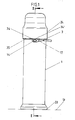
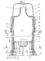
- the dispenser which is matched to the dispensing of pasty filling contents, has an essentially cylindrical housing tube 1.
- the dispenser ends at the top with a screw-on ceiling 4, which narrows in a funnel shape to a central dispensing opening 5.
- the ceiling 4 is in screw engagement with the cylindrical housing tube 1, for which the latter in the area of its upper edge Internal thread 6 carries, which cooperates with the corresponding external thread of the cover 4 designed to form a cap body.
- the cap wall 7 forms an annular collar 8, which rests on the upper end edge 1 ⁇ of the housing tube 1 in a stop-limiting manner.
- a sack 9 containing the pasty mass M made of plastic film, fabric or the like This has the shape of a "sausage” tied at both ends. It also has a cylindrical shape and, while leaving a jacket-side annular gap, practically freely upright in the dispenser housing 1. From the so-called “sausage tips", the upper, gathered sack wall end 9 ⁇ grips in a practically sleeve-like manner through the dispensing opening 5, just above which it is separated. The other, with a seal 10 held closed bag wall end 9 ⁇ protrudes into a central recess 11 of the pressure base 2nd
- the pasty mass M is squeezed out of the sack 9 via a handle-induced axial pulling movement of two diametrically opposed transport toothed strips 12.
- Their steep tooth flanks 12 ⁇ drag the pressure base 2 in the direction of the arrow x.
- 2 ratchet tongues 13 start from the pressure floor. They are formed by a collar of the pot-shaped pressure base. The collar is interrupted in a crenellated manner, so that there are individual radially movable fingers, which engage with their slightly outwardly angled ends in a form-fitting manner in the transport toothed strip 12.
- the flatter flank 12 ⁇ of the transport strips 12 is freely overrun by the ratchet tongues 13 in the event of a counter-movement.
- the actuating handle 3 engaging the teeth 14 of the two transport toothed strips 12 is designed as a double-armed lever.
- the actuating handle bifurcates as shown in FIG. 5.
- the two correspondingly curved fork tines 16 are mounted at mutually opposite locations on the housing tube 1.
- the bearings have the reference number 17. They are outside the diametrals.
- the end region opposite the actuating handle button 18 protruding to the side, which is the shorter arm of the lever, is articulated by means of the clip connection with the pin 14.
- the free, split end of the fork tines 16 can be spread apart against the restoring force of the material and snapped over the thickened head of the pin 14. The head then lies in one vertical jaw, while the opposite vertical jaw facing the housing tube 1 blocks the threading path by means of a nose 16 ⁇ .
- the bearing 17, i. the recess in the wall of the housing tube 1 receiving a hinge pin of the fork tines 16 is chosen to be significantly larger, practically implemented as a horizontal longitudinal slot 19.
- the abutment toothed racks 20 which are axially displaceable via the actuating handle 3 are adjacent to abutment toothed racks 20 which are not included in this movement.
- the latter have the same sawtooth-like structure as the transport toothed strips 12, that is to say also a steep flank 20 ⁇ , that is to say perpendicular to the direction of displacement of the pressure base 2, and a spillable back which is formed by a fairly flat flank 20 ⁇ .
- the respective flanks are aligned Circulation direction, ie the edge 12 ⁇ is at the same height as the edge 20 ⁇ etc.
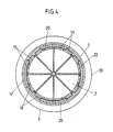
- the insert is designed as a sleeve with circumferentially arched rod-like elements.
- the transport toothed strips 12 and the abutment toothed strips 20 are coupled to one another by edge-side webs 22.
- the sleeve thus formed ends with a continuous ring collar 23 and 24, respectively.
- the upper ring collar 23 is chamfered on the outside at 25, so that it is easier to insert the sleeve from the bottom.
- the webs 22 lie in the annular surface plane of the sleeve and correspond to the toothing which occupies an exposed position back. They start from the vertical longitudinal edges of the neighboring strips.
- the movable transport toothed strips 13 are practically suspended in a window cavity 26.
- a distance y remains on both sides and, on the upper side, a smaller axial distance y ⁇ than the window frame bridged only by the webs 22.
- the end of the transport toothed strip 12 is practically at a distance corresponding to a light gap in front of the annular collar 24 there.
- the dimension y ⁇ takes into account the working stroke required for the transport actuation.
- the webs 22 essentially start in the end regions of the transport toothed strips 20. Starting from the vertical marginal edge of the abutment toothed strips 20, they initially take a right-angled course, but then run into the corresponding marginal edge of the transport toothed strips 12 substantially perpendicularly in a clear curvature.
- the webs 22 also perform the function of return springs, so that after releasing the actuating handle 3, the basic position of the mechanics always occurs again.
- the corresponding spring force is dimensioned such that the transport toothed strip 12 moves back from the raised position, dragging the pressure base 2 upward, overflowing the ratchet tongues 13 into the starting position.
- the lower, i.e. standing collar collar 24 is designed to be flexible in the axial direction. This is achieved by longitudinal slots 28 which run in the circumferential direction and are interrupted by axial webs 27. Viewed in the axial direction, two such longitudinal slots 28 extend one behind the other.
- the webs 27 sit once in the plane of symmetry of the transport toothed bar 12 and adjacent to it in the plane of symmetry of the abutment toothed bar 20.
- the sleeve In the unloaded state, the sleeve returns to its initial position shown in FIG. 3.
- the load of the output goods causes them to be pushed together by the clearance dimension z.
- this structural skeleton occupies an ossified position, i.e. the horizontal ring sections touch against the corresponding longitudinal slot flanks (Fig. 7).
- this button is actuated, this partial stroke shown as clearance z is always run through; Only then does the lifting section bring about the overflow of the abutment toothed strips 20 of the tooth lock (approx. two teeth), which reduces the volume between the pressure floor 2 and the ceiling 4. If the actuating handle is released, the transport toothed strips 12 pull back into their starting position while underneath the ratchet tongues 13. Meanwhile, the pressure floor 2 is supported on the "local" abutment toothed strips 20. When the next basic ratchet position has been reached, the insert 21 then drops and with it the pressure base 2 supported on it downwards by the amount of the described clearance z. The mass M relaxes a little. The latter leads to a suction effect which sucks any excess paste in front of the discharge opening 5 into the sack 9.
- the lower ring collar 24 of the sleeve-shaped insert 21 is also designed in the sense of a captive assignment on the housing tube 1; For this purpose, it has an annular groove 30 on its lateral surface, into which an annular bead 31 of said tube housing 1 projects in a form-fitting manner.
- a groove structure is chosen which is so large that an annular collar 32 of a stand ring 33 assigned to the housing tube 1 also finds its hold there.
- the dispenser has a protective cap 34.
- the latter overlapping the ceiling 4 like a dome, is screwed onto the upper end of the housing tube 1, which has the corresponding counter thread.
- the lower edge 34 ⁇ of the protective cap 34 locks over the free end of the fork prongs 16 of the actuating handle 3, so that the dispenser is blocked against dispensing when the protective cap 34 is properly screwed on.
- the screw limiting stop is formed by an annular collar 35 which, in the creation of a space for the shorter lever arm in the region of the section of the actuating handle 3 forming the shorter lever arm, forms an opening 36 which is open at the top.
Landscapes
- Engineering & Computer Science (AREA)
- Mechanical Engineering (AREA)
- Containers And Packaging Bodies Having A Special Means To Remove Contents (AREA)
- Coating Apparatus (AREA)
- Encapsulation Of And Coatings For Semiconductor Or Solid State Devices (AREA)
- Formation And Processing Of Food Products (AREA)
Priority Applications (1)
| Application Number | Priority Date | Filing Date | Title |
|---|---|---|---|
| AT87100104T ATE46487T1 (de) | 1986-03-01 | 1987-01-07 | Spender. |
Applications Claiming Priority (2)
| Application Number | Priority Date | Filing Date | Title |
|---|---|---|---|
| DE19863606711 DE3606711A1 (de) | 1986-03-01 | 1986-03-01 | Spender |
| DE3606711 | 1986-03-01 |
Publications (3)
| Publication Number | Publication Date |
|---|---|
| EP0235501A2 true EP0235501A2 (fr) | 1987-09-09 |
| EP0235501A3 EP0235501A3 (en) | 1988-10-19 |
| EP0235501B1 EP0235501B1 (fr) | 1989-09-20 |
Family
ID=6295266
Family Applications (1)
| Application Number | Title | Priority Date | Filing Date |
|---|---|---|---|
| EP87100104A Expired EP0235501B1 (fr) | 1986-03-01 | 1987-01-07 | Distributeur |
Country Status (7)
| Country | Link |
|---|---|
| US (1) | US4763815A (fr) |
| EP (1) | EP0235501B1 (fr) |
| JP (1) | JPS62220468A (fr) |
| AT (1) | ATE46487T1 (fr) |
| AU (1) | AU6854787A (fr) |
| CA (1) | CA1279617C (fr) |
| DE (2) | DE3606711A1 (fr) |
Families Citing this family (24)
| Publication number | Priority date | Publication date | Assignee | Title |
|---|---|---|---|---|
| US5178300A (en) * | 1990-06-06 | 1993-01-12 | Shlomo Haviv | Fluid dispensing unit with one-way valve outflow |
| US5118007A (en) * | 1990-10-23 | 1992-06-02 | Lewis Catherine A | Tablet dispenser |
| US5169034A (en) * | 1991-02-04 | 1992-12-08 | George Kozam | Fluid dispensing apparatus with pulsed stream |
| DE4216541C2 (de) * | 1992-05-19 | 1995-02-16 | Sigismund Laskowski | Mehrfach verwendbarer Dosierspender |
| US5356037A (en) * | 1993-06-21 | 1994-10-18 | Pakmax, Inc. | Lift and drop ratchet stick dispenser |
| US6484897B1 (en) | 1995-02-13 | 2002-11-26 | Amcad Holdings Limited | Containers with variable volume |
| KR19980702202A (ko) * | 1995-02-13 | 1998-07-15 | 안 크로우베이 | 가변체적을 갖는 용기 |
| US6085807A (en) * | 1999-06-04 | 2000-07-11 | Vector Corporation | Constant drop tablet receptacle |
| US6173869B1 (en) * | 1999-09-23 | 2001-01-16 | Color Access, Inc. | Multi-piston, ratcheted dispensing device |
| US6779664B1 (en) * | 2002-02-15 | 2004-08-24 | Ronnie J. Bermann | Device for dispensing sandwiches |
| US8297481B2 (en) * | 2005-08-01 | 2012-10-30 | Rich Products Corporation | Dispensing device |
| US8561854B2 (en) * | 2005-08-01 | 2013-10-22 | Rich Products Corporation | Dispensing device for viscous materials |
| US20090014473A1 (en) * | 2007-07-15 | 2009-01-15 | Meir Gitelis | Tube-Dispenser |
| WO2009050698A2 (fr) * | 2007-10-18 | 2009-04-23 | Meir Gitlis | Distributeur tubulaire |
| MX2012002476A (es) | 2009-09-16 | 2012-03-26 | Colgate Palmolive Co | Sistema, kit y metodo para el cuidado oral. |
| US8523475B2 (en) | 2009-12-23 | 2013-09-03 | Colgate-Palmolive Company | Oral care system, kit and method |
| KR101513342B1 (ko) | 2009-12-23 | 2015-04-17 | 콜게이트-파아므올리브캄파니 | 구강 관리 시스템 |
| BR112012015730A2 (pt) | 2009-12-23 | 2021-07-06 | Colgate Palmolive Co | sistema de tratamento bucal. |
| PH12012500882A1 (en) | 2009-12-23 | 2013-01-07 | Colgate Palmolive Co | Oral care system, kit and method |
| KR101528395B1 (ko) | 2009-12-23 | 2015-06-11 | 콜게이트-파아므올리브캄파니 | 구강 관리 시스템 |
| EP3169186B1 (fr) | 2014-08-14 | 2022-04-13 | Colgate-Palmolive Company | Système et procédé de soin buccal |
| WO2016024983A1 (fr) | 2014-08-14 | 2016-02-18 | Colgate-Palmolive Company | Système et procédé de soins bucco-dentaires |
| AU2015381790B2 (en) | 2015-02-02 | 2018-10-04 | Colgate-Palmolive Company | Oral care system and oral care material dispenser |
| US20230145881A1 (en) * | 2020-03-06 | 2023-05-11 | Herve Edibles Limited | Dispenser for frangible food product |
Family Cites Families (12)
| Publication number | Priority date | Publication date | Assignee | Title |
|---|---|---|---|---|
| FR444627A (fr) * | 1912-06-05 | 1912-10-22 | Craven Engineering Company | Système de récipient pour contenir et débiter des substances semi-solides ou pateuses |
| FR850458A (fr) * | 1939-02-17 | 1939-12-18 | Récipient à piston pour matières pâteuses | |
| US2627365A (en) * | 1948-02-25 | 1953-02-03 | Gabler Josef | Cream box |
| US2496464A (en) * | 1948-08-27 | 1950-02-07 | Clarence M Gentry | Tape cylinder mounting |
| US2689066A (en) * | 1952-02-26 | 1954-09-14 | Budnik Joseph | Dispensing holder for paste tubes having means for compressing a tube |
| US3255935A (en) * | 1965-03-29 | 1966-06-14 | Walter B Spatz | Dispensers for fluent masses |
| US3920156A (en) * | 1975-02-24 | 1975-11-18 | Leslie E Hicks | Incremental butter dispenser |
| DE3036256A1 (de) * | 1980-07-03 | 1982-09-30 | Schneider GmbH, 6272 Niedernhausen | Verpackungsbehaelter mit entnahmeeinrichtung fuer breiige, fliessfaehige substanzen |
| FR2489267A1 (fr) * | 1980-09-01 | 1982-03-05 | Castanet Raymond | Dispositif permettant de contenir et de distribuer des objets de facon unitaire ou fractionnee |
| US4437584A (en) * | 1981-08-28 | 1984-03-20 | Colgate-Palmolive Company | Toothpaste dispenser |
| US4487341A (en) * | 1981-10-01 | 1984-12-11 | Colgate-Palmolive Company | Dispenser for dispensing creams and especially self-foaming gels |
| DE3445121A1 (de) * | 1984-12-11 | 1986-06-12 | Bramlage Gmbh, 2842 Lohne | Spender zur einzelausgabe von tabletten oder dergleichen |
-
1986
- 1986-03-01 DE DE19863606711 patent/DE3606711A1/de not_active Withdrawn
-
1987
- 1987-01-07 AT AT87100104T patent/ATE46487T1/de not_active IP Right Cessation
- 1987-01-07 EP EP87100104A patent/EP0235501B1/fr not_active Expired
- 1987-01-07 DE DE8787100104T patent/DE3760576D1/de not_active Expired
- 1987-02-05 AU AU68547/87A patent/AU6854787A/en not_active Abandoned
- 1987-02-27 CA CA000530733A patent/CA1279617C/fr not_active Expired - Lifetime
- 1987-02-28 JP JP62044149A patent/JPS62220468A/ja active Pending
- 1987-03-02 US US07/020,518 patent/US4763815A/en not_active Expired - Fee Related
Also Published As
| Publication number | Publication date |
|---|---|
| AU6854787A (en) | 1987-09-03 |
| CA1279617C (fr) | 1991-01-29 |
| JPS62220468A (ja) | 1987-09-28 |
| EP0235501A3 (en) | 1988-10-19 |
| EP0235501B1 (fr) | 1989-09-20 |
| DE3606711A1 (de) | 1987-09-03 |
| US4763815A (en) | 1988-08-16 |
| ATE46487T1 (de) | 1989-10-15 |
| DE3760576D1 (en) | 1989-10-26 |
Similar Documents
| Publication | Publication Date | Title |
|---|---|---|
| EP0235501B1 (fr) | Distributeur | |
| EP0053275B1 (fr) | Distributeur pour matériel pâteux | |
| EP0036491B1 (fr) | Distributeur pour produits pâteux | |
| EP0053329B1 (fr) | Récipient pour distribuer en portions un produit de consistance pâteuse | |
| EP0276474B1 (fr) | Appareil de dosage | |
| EP0226777A2 (fr) | Distributeur pour matières pâteuses | |
| EP1117489A1 (fr) | Pistolet calfeutreur | |
| EP0248278B1 (fr) | Distributeur pour délivrer les doses unitaires d'une pâte ou similaire | |
| DE69907039T2 (de) | Biegsamer antriebsmechanismus sowie abgabevorrichtung enthaltend einen solchen mechanismus | |
| EP0376097A2 (fr) | Distributeur-doseur d'un produit pâteux | |
| EP0315077A1 (fr) | Distributeur pour produits pâteux | |
| DE4216541C2 (de) | Mehrfach verwendbarer Dosierspender | |
| EP0184742B1 (fr) | Distributeur pour la décharge en portion unique de pastilles, pâtes ou similaires | |
| DE3618399A1 (de) | Spender | |
| EP0431304A2 (fr) | Dispositif pour l'expulsion par étapes d'un produit | |
| DE3338933A1 (de) | Spender fuer pastoese massen | |
| DE3343680A1 (de) | Spender fuer pastoese massen, insbesondere zahncremespender | |
| EP0481250A1 (fr) | Cartouche destinée à être introduite dans un distributeur | |
| EP0388741B1 (fr) | Cartouche pour distributeur | |
| DE3618398A1 (de) | Spender | |
| EP0422698A2 (fr) | Distributeur | |
| EP0909544A1 (fr) | Distributeur de savon | |
| DE8614745U1 (de) | Spender | |
| EP0430312A2 (fr) | Distributeur pour délivrer les doses unitaires de pâtes ou similaires | |
| EP0419967A1 (fr) | Distributeur |
Legal Events
| Date | Code | Title | Description |
|---|---|---|---|
| PUAI | Public reference made under article 153(3) epc to a published international application that has entered the european phase |
Free format text: ORIGINAL CODE: 0009012 |
|
| AK | Designated contracting states |
Kind code of ref document: A2 Designated state(s): AT BE CH DE ES FR GB GR IT LI LU NL SE |
|
| PUAL | Search report despatched |
Free format text: ORIGINAL CODE: 0009013 |
|
| AK | Designated contracting states |
Kind code of ref document: A3 Designated state(s): AT BE CH DE ES FR GB GR IT LI LU NL SE |
|
| 17P | Request for examination filed |
Effective date: 19881124 |
|
| 17Q | First examination report despatched |
Effective date: 19890306 |
|
| GRAA | (expected) grant |
Free format text: ORIGINAL CODE: 0009210 |
|
| AK | Designated contracting states |
Kind code of ref document: B1 Designated state(s): AT BE CH DE ES FR GB GR IT LI LU NL SE |
|
| PG25 | Lapsed in a contracting state [announced via postgrant information from national office to epo] |
Ref country code: GR Free format text: LAPSE BECAUSE OF FAILURE TO SUBMIT A TRANSLATION OF THE DESCRIPTION OR TO PAY THE FEE WITHIN THE PRESCRIBED TIME-LIMIT Effective date: 19890920 Ref country code: BE Effective date: 19890920 |
|
| REF | Corresponds to: |
Ref document number: 46487 Country of ref document: AT Date of ref document: 19891015 Kind code of ref document: T |
|
| ET | Fr: translation filed | ||
| REF | Corresponds to: |
Ref document number: 3760576 Country of ref document: DE Date of ref document: 19891026 |
|
| GBT | Gb: translation of ep patent filed (gb section 77(6)(a)/1977) | ||
| ITF | It: translation for a ep patent filed | ||
| PGFP | Annual fee paid to national office [announced via postgrant information from national office to epo] |
Ref country code: FR Payment date: 19891221 Year of fee payment: 4 |
|
| PG25 | Lapsed in a contracting state [announced via postgrant information from national office to epo] |
Ref country code: ES Free format text: LAPSE BECAUSE OF FAILURE TO SUBMIT A TRANSLATION OF THE DESCRIPTION OR TO PAY THE FEE WITHIN THE PRESCRIBED TIME-LIMIT Effective date: 19891231 |
|
| PG25 | Lapsed in a contracting state [announced via postgrant information from national office to epo] |
Ref country code: AT Effective date: 19900107 |
|
| PG25 | Lapsed in a contracting state [announced via postgrant information from national office to epo] |
Ref country code: SE Effective date: 19900108 |
|
| PG25 | Lapsed in a contracting state [announced via postgrant information from national office to epo] |
Ref country code: LU Free format text: LAPSE BECAUSE OF NON-PAYMENT OF DUE FEES Effective date: 19900131 |
|
| PGFP | Annual fee paid to national office [announced via postgrant information from national office to epo] |
Ref country code: CH Payment date: 19900403 Year of fee payment: 4 |
|
| PLBE | No opposition filed within time limit |
Free format text: ORIGINAL CODE: 0009261 |
|
| STAA | Information on the status of an ep patent application or granted ep patent |
Free format text: STATUS: NO OPPOSITION FILED WITHIN TIME LIMIT |
|
| PG25 | Lapsed in a contracting state [announced via postgrant information from national office to epo] |
Ref country code: NL Effective date: 19900801 |
|
| 26N | No opposition filed | ||
| NLV4 | Nl: lapsed or anulled due to non-payment of the annual fee | ||
| PG25 | Lapsed in a contracting state [announced via postgrant information from national office to epo] |
Ref country code: GB Effective date: 19910107 |
|
| PGFP | Annual fee paid to national office [announced via postgrant information from national office to epo] |
Ref country code: DE Payment date: 19910130 Year of fee payment: 5 |
|
| ITTA | It: last paid annual fee | ||
| PG25 | Lapsed in a contracting state [announced via postgrant information from national office to epo] |
Ref country code: LI Effective date: 19910131 Ref country code: CH Effective date: 19910131 |
|
| GBPC | Gb: european patent ceased through non-payment of renewal fee | ||
| PG25 | Lapsed in a contracting state [announced via postgrant information from national office to epo] |
Ref country code: FR Effective date: 19910930 |
|
| REG | Reference to a national code |
Ref country code: CH Ref legal event code: PL |
|
| REG | Reference to a national code |
Ref country code: FR Ref legal event code: ST |
|
| PG25 | Lapsed in a contracting state [announced via postgrant information from national office to epo] |
Ref country code: DE Effective date: 19921001 |
|
| EUG | Se: european patent has lapsed |
Ref document number: 87100104.6 Effective date: 19901107 |
|
| PG25 | Lapsed in a contracting state [announced via postgrant information from national office to epo] |
Ref country code: IT Free format text: LAPSE BECAUSE OF NON-PAYMENT OF DUE FEES;WARNING: LAPSES OF ITALIAN PATENTS WITH EFFECTIVE DATE BEFORE 2007 MAY HAVE OCCURRED AT ANY TIME BEFORE 2007. THE CORRECT EFFECTIVE DATE MAY BE DIFFERENT FROM THE ONE RECORDED. Effective date: 20050107 |