EP0235602A2 - Verfahren zum Messen und Schleifen eines Schienenkopfprofils - Google Patents
Verfahren zum Messen und Schleifen eines Schienenkopfprofils Download PDFInfo
- Publication number
- EP0235602A2 EP0235602A2 EP87101477A EP87101477A EP0235602A2 EP 0235602 A2 EP0235602 A2 EP 0235602A2 EP 87101477 A EP87101477 A EP 87101477A EP 87101477 A EP87101477 A EP 87101477A EP 0235602 A2 EP0235602 A2 EP 0235602A2
- Authority
- EP
- European Patent Office
- Prior art keywords
- grinding
- profile
- distance
- facets
- head
- Prior art date
- Legal status (The legal status is an assumption and is not a legal conclusion. Google has not performed a legal analysis and makes no representation as to the accuracy of the status listed.)
- Granted
Links
Images



Classifications
-
- E—FIXED CONSTRUCTIONS
- E01—CONSTRUCTION OF ROADS, RAILWAYS, OR BRIDGES
- E01B—PERMANENT WAY; PERMANENT-WAY TOOLS; MACHINES FOR MAKING RAILWAYS OF ALL KINDS
- E01B31/00—Working rails, sleepers, baseplates, or the like, in or on the line; Machines, tools, or auxiliary devices specially designed therefor
- E01B31/02—Working rail or other metal track components on the spot
- E01B31/12—Removing metal from rails, rail joints, or baseplates, e.g. for deburring welds, reconditioning worn rails
- E01B31/17—Removing metal from rails, rail joints, or baseplates, e.g. for deburring welds, reconditioning worn rails by grinding
Definitions
- the invention relates to a method for measuring and rectifying the profile of a rail head and a grinding car for implementing the method.
- the average amplitude of the short wave wavelength deformations, the amplitude of the long wavelength wave deformations and the amplitude of the profile defect of the head mushroom are measured. , these quantities being obtained by means of a circuit for shaping the data delivered by probes.
- the signals corresponding to these quantities are introduced into a computer, into which are also introduced the known values of the working power of the grinding tools such as for example the grinding pressure, the speed of advance of the grinding tools, l angle of inclination of the grinding tools and the speed of advance of the grinding vehicle along the track.
- This computer is designed so that it delivers signals according to a recorded calculation program, these signals corresponding to the set values of the various working data of the grinding tools.
- control circuits which control the grinding tools. It is carried out in such a way that the quantities representative of the condition of the rail mushrooms are measured both before and after grinding by means of two measuring carriages placed in front and behind the rectification vehicle. Corrections are made on the basis of the second measurement made after rectification.
- the approximation of the target profile of the rail head is obtained by controlling in particular the grinding pressure, the grinding speed, the inclination of the grinding tool and the speed of advance of the vehicle, these working quantities being dependent on a set value which is itself determined as a function of the grinding depth. It does not appear from the document when it is necessary to stop the grinding so that the set profile is approximately obtained optimally along one or more generators and no relationship is given between the generators on which the probes are adjusted and the generators to which one or more grinding tools are adjusted in order to grind a corresponding facet.
- the distances between a reference base and the two generators located on the edges of the running surface of the rail as well as a generator are determined. intermediate, in order to obtain the curvature of the running surface of the rail.
- the deflection of the arc of the rail running surface at the location of the intermediate generator is determined, on the one hand, and the inclination of the connecting cord, on the other. the two external generators relative to the track plan.
- the measurement is carried out by means of electronic sensors not in contact with the rail, for example capacitive, optical or eddy current sensors.
- EP-AO 032 214 is also known a grinding car in which the grinding pads movable in height, on which are mounted several grinding tools, are angularly adjustable relative to the rolling grinding frame, in a plane perpendicular to the axis of the track.
- each grinding unit is individually orientable relative to its grinding wheel and it can be applied against the track with a determined inclination.
- a known device for the continuous measurement of the profile of the head of a rail (EP-A-O 114 284) is equipped with several mechanical probes produced and arranged so as to have a small footprint.
- the object of the present invention is to simplify and to design the measurement and the rectification of the rail mushrooms so that the approximation of the target profile can be carried out with more accuracy than hitherto and by means of control devices. relatively simple.
- the setpoint profile is characterized simply by the distances directly measured between the reference base and a sufficient number of generators, without these direct measurements having to be transformed into others quantities such as angle tilt, arrow or the like; similarly, the grinding necessary to reach the setpoint profile is controlled simply by a comparison, easy to perform electronically, between the actual distances and the setpoint distances, which makes it possible to approach the setpoint profile in a simple, direct manner and optimal, because the grinding operation on each generator is automatically interrupted when the difference between the set distance and the actual distance reaches 0.
- FIG. 1 represents a grinding car 2 with two axles 3 movable on track 1 and provided at one of its ends with a measurement frame 4.
- This measurement frame 4 has a measurement head 5 for each of the tracks 1, as shown diagrammatically in FIG. 2.
- On each of the measuring heads are fixed sensors C working without contact.
- each measuring head 5 is provided with seven probes C1 to C7.
- the two measuring heads 5 are supported on the middle of the rail by a shoe 6 and are articulated on the car 2 by a connecting rod 10.
- the measuring heads 5 are guided laterally by rollers 7 rolling on the inside of the rails 1 against which they are held in abutment by a spacer device 8 mounted between the two measurement heads by means of a hydraulic cylinder 9.
- a device fixed to the chassis of the grinding car 2 and acting hydraulically on the two measuring heads 5, represented diagrammatically in FIG. 1 by the arrow 11, ensures that the pads 6 are in permanent contact with the rails with a sufficient force. It is thus ensured that during the advance of the grinding car, each sensor C follows a determined generator of the rail head.
- the axes of the sensors C1 to C6 are aligned on six generators s1 to s6, as shown in FIG. 3. These six prescribed generators are approximately evenly distributed over the region of the running surface of the rail which extends over a mean arc of the profile of the rail head.
- This medium arc has a relatively large radius generally about 300mm and the rays passing through the ends of this arc form with the radius passing through the middle of the arc, that is to say the middle of the rail head, an angle of about 15 °.
- a seventh sensor C7 is provided, indicated only by its axis, which is adjusted on a generator s7.
- This C7 sensor is used, as will be explained further on by means of FIGS. 6, 8 and 9, to the extent of the bead generally appearing on the outside of the rail 1 and commonly known as the "outside radius".
- the sensors C are, for example, inductive measuring instruments. Each sensor C is arranged so as to measure the distance h separating it from the generator on which it is adjusted.
- the reference points of this base are, in the example according to FIG. 3, the lower ends of the sensors C.
- the grinding car 2 is equipped between its two axles 3, with two grinding units 12 and 13 per rail, these units being fixed to the chassis 20 of the car in a known manner and resting on the rails.
- Each of the grinding units 12 and 13 has two grinding head supports 14 and 18 each carrying a double grinding head 15, respectively 19 provided with two grinding heads 16 and 16 ⁇ , respectively 17 and 17 ⁇ , as shown schematically for the grinding unit 12 in FIG. 1.
- Each grinding head support 14 and 18 is pivotable in a manner known per se in a plane perpendicular to the axis of the track and adjustable in height.
- Figure 4 shows schematically the grinding head support 14 in the raised position. It can be pivoted by a determined angle ⁇ and its axis B can be directed on a determined generator s. It can also be raised and lowered.
- the angle of inclination ⁇ is equal to the angle formed by the horizontal H with the tangent T to the profile of the rail 1 at the point of intersection of the axis B of the support of grinding head 14 and generator s.
- this angle of inclination ⁇ is equal to the angle between the radius of the profile of the rail passing through the generator s and the perpendicular bisector of the rail.
- the two grinding heads 16, 16 ⁇ , respectively 17, 17 ⁇ can be individually oriented relative to their support 14, respectively 18, in a plane perpendicular to the axis of the rail and they can be moved in the direction of their axis. of rotation. In this way the two grinding heads of each support 14 and 18 can be adjusted relative to each other so that their grinding planes intersect at a prescribed working angle ⁇ , as shown schematically in FIG. 4 for the support 14.
- the two flat grinding wheels 16a and 16a ⁇ of the two grinding heads 16 and 16 ⁇ are shown here with their axes of rotation A, respectively A ⁇ , the grinding planes of these grinding wheels forming the working angle ⁇ .
- this double grinding head 15 simultaneously forms the two facets f and f ⁇ indicated in dashed lines in FIG. 4.
- the angle of inclination ⁇ of the grinding head support does not necessarily have to be defined relative to the inclination of the bisector of the angle formed by the axes of rotation A and A ⁇ of the grinding heads, respectively relative to the axis of symmetry B of the grinding head support, but it can refer to another reference line of this support, for example to the axis of rotation of one of the grinding heads 16 or 16 ⁇ this above all when this grinding head is mounted fixed relative to the support of grinding heads and only the other grinding head is adjustable for adjustment of the working angle ⁇ relative to the support of the grinding heads.
- the angle of inclination of the double grinding head coincides with the angle of inclination of one of the grinding wheels and therefore of the corresponding facet.
- Figure 4a schematically shows a double grinding head with a grinding head support 14 on which are mounted one behind the other the two grinding heads 16 and 16 ⁇ with their drive motors 16b and 16 ⁇ b and their flat wheels 16a and 16 ⁇ a.
- the head holder 14 essentially consists of support parts such as the part 28, on which the grinding heads 16 and 16 ⁇ are fixed, an L-shaped frame 23, a lever 27 connecting the lower ends of the part support 28 and the frame 23 and a jack 24 mounted between the upper end of the support piece 28 and the middle of the frame 23.
- the frame 23 is suspended from the chassis 20 of the car 2 so that its part upper 23a is supported on a guide segment 21 in an arc of circle on which it can move by sliding or rolling.
- the lever 27, articulated at an intermediate point on the frame 23, has its other end articulated at the end of a pneumatic cylinder 25, the other end of which is attached at 26 to the support 23 and which serves to relieve the double head of grinding and adjusting the force with which the wheels 16a and 16 ⁇ a are applied against the rail 1.
- the cylinder 25 is double-acting. In extension there raises the grinding head holder by means of the lever 27, while in retraction it presses the grinding wheels 16a and 16 ⁇ a against the rail 1.
- a jack 22 mounted approximately horizontally between one of the sides of the frame 20 and the upper arm 23a of the L-shaped frame 23.
- This double-acting cylinder 22 ensures the movement of the frame 23 on the arc of a circle of the guide segment 21.
- the frame 23 pivots around its articulation on the lever 27 by driving the support 28 by the jack 24 which then functions as a rigid bar between the frame 23 and the support 28, which in turn pivots with the grinding head 16 around its articulation on the lever 27.
- the other grinding head 16 ⁇ located behind the grinding head 16, is rigidly fixed to the frame 23, so that when the frame 23 pivots, the two grinding heads are driven simultaneously, the grinding head 16 ⁇ directly and the grinding head 16 by means of the cylinder setting 24.
- the working angle ⁇ is preferably adjustable between 0 ° and 10 °, either continuously or step by step. In the case of grinding the running surface of the rail, these steps can correspond, for example, to 1 °, 2 ° and 4 °.
- the two grinding heads 16 and 16 ⁇ can be moved individually relative to the frame 23, each by a jack corresponding to the jack 24.
- a grinding head holder 14 is equipped with more than one pair of grinding heads
- the grinding heads working on the same facet that is to say adjusted to the same angle of inclination, can be controlled by a common pneumatic cylinder so that they work with the same grinding pressure.
- the actual profile in the area of the running surface of the rail should be measured and checked on at least 6 generators and the complete profile on minus 14 generators.
- the grinding of the running surface of the rail will be described below.
- the installation is therefore arranged in such a way that a sensor C and one of the grinding head holders 14, 18 are adjusted on the same generator coinciding with the ridge line of the two adjacent facets which must be ground by this double grinding head.
- a single sensor C thus simultaneously measures and controls the position of two facets so that with a given number of sensors, six sensors in the example considered, the target profile of the rail running surface is approached by a number twice as many facets, twelve facets in the example considered.
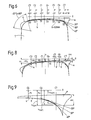
- FIG. 5 diagrammatically illustrates the control of the profile of the running surface of the rail by means of six sensors C1 to C6 directed on the generators s1 to s6 and permanently measuring the distances h1 to h6 between these sensors and the reference line 0 before and during the grinding operation.
- This reference line 0, corresponding to the lower ends of the sensors defining the reference base has been represented by a horizontal line in FIGS. 5, 6, 8 and 9 for simplicity.
- the six generators s1 to s6 coincide with the ridge lines of two neighboring facets grinded simultaneously by the two grinding wheels 16 and 16 ⁇ of a double grinding head 15 ( Figure 4).
- the planes of the two grinding wheels of each double grinding head form a given angle ⁇ 1 to ⁇ 6 adapted to the set profile.
- the installation is preferably arranged so that the two grinding wheels of a grinding head holder, when adjusting this holder head on a specific generator, are automatically adjusted to a working angle ⁇ corresponding to this generator.
- each rail generally called internal radius and external radius
- each of these arcs whose radius is significantly smaller than the radius of the intermediate arc forming the rolling surface, should be controlled by at least four sensors, so that a total of at least 14 sensors would be required to full measurement of the profile of a rail.
- This known grinding device works with direct monitoring and control of the grinding heads. It is recommended to grind at least the internal radius guiding the wheels laterally by this known process.
- the outer radius which generally has a more or less pronounced bead after a certain period of use, and if necessary also the inner radius, according to the method and with a machine according to the present invention.
- the grinding of the arc or external radius can be advantageously carried out by means of a single sensor in the region of the bead as will be described below.
- FIG. 6 schematically illustrates the arrangement of the double grinding heads associated with the sensors C1 to C6 by the indication of their angles of inclination ⁇ which they exhibit respectively when they are added to each of the generators s1 to s6, and by l working angle ⁇ corresponding between their two grinding planes.
- Negative ⁇ values refer to half of the rail head located on the inside. The running surface of the rail extends on each side of the perpendicular bisector up to an angle of 15 °.
- FIG. 6 schematically illustrates the rectification of the external arc of the rail 1 by means of a single sensor C7 indicated only schematically and which controls the generator s7 also indicated in FIG. 3, and by means of a double head ali grinding gned on the generator s7, whose values ⁇ and ⁇ are given and therefore the inclination is modified step by step.
- the initial real profile is designated by a and the target profile by b.
- the target profile by b.
- the inner arc of the rail which extends, in the example considered, over an angle of -15 ° to -80 °, and rectify by means of side grinders according to the known prior process mentioned above.
- Each of the halves of the rolling surface is thus approached by six facets having angles of inclination of 0 °, 1 °, 3 °, 6 °, 9 ° and 12 °, if the two grinding heads of FIG. 4 are symmetrical relative to the median axis of the double grinding head defining the angle ⁇ .
- the sensor C7 is aligned on the generator s7 passing through the contact point of the tangent at 45 ° to the theoretical roughing profile, that is to say on the radius forming an angle of 45 ° with the rail bisector.
- This double grinding head is first of all adjusted to an angle of inclination ⁇ of 20 °, for example, and it grinds in this position the bead e until the sensor C7 measures a predetermined distance for which the grinding wheel located on the interior side is precisely in a plane tangential to the roughing profile.
- the same grinding operation is then repeated step by step in the area of the sensor C7, with reduced pressure, until the set profile b is reached.
- Each double grinding head is preferably angularly adjustable over an angle of -15 ° to + 45 °, that is to say over the whole of the rolling surface and of the external arc, so that if necessary, each of the double grinding heads can work along each of the generators.
- the working angle ⁇ is preferably adjustable continuously or in steps up to 10 °.
- the step-by-step grinding of the external arc described makes it possible to control several pairs of grinded facets successively, by means of a single sensor, which naturally simplifies the installation extraordinarily and reduces the number of sensors required.
- six facets are advantageously obtained in three steps, which makes it possible to achieve a good approximation of the set profile of the external arc.
- an approximation of the external arc is obtained with the values given ⁇ and ⁇ by facets having inclinations equal to 17 °, 23 °, 27 °, 33 °, 42 ° and 48 °.
- the deburring of the bead e in the region of the external arc of the rail, as described, can naturally also be carried out by means of a single grinding wheel aligned on the generator s7 and whose grinding plane is adjusted successively to inclinations gradually increasing.
- the outer arc of the rail is approached by fewer facets than when working with a double grinding head, but on the other hand the number of steps is increased.
- the angles given ⁇ represent the inclination of the grinding wheel, it would be three facets having the inclinations 20 °, 30 ° and 45 ° which would all be controlled with the same sensor C7 set on the facet at 45 °.
- this device installed on the grinding car, comprises an analyzer 30 to which the outputs of all the sensors C measurement heads are connected and which receives the signals delivered by these sensors C which represent the actual distances measured h.
- this analyzer 30 are recorded the different theoretical profiles of the tracks in the form of distances that the reference profile of the rail to be rectified must present between the given generators and the reference line 0.
- the six reference distances h1 to h6, in the area of the rolling surface, which are controlled by the sensors C1 to C6 , are saved in the analyzer.
- the setpoint profile b defined by its setpoint distances refers to the distance h0 between the generator of the medium, that is to say the axis of the rail, and the reference line, distance which is determined by the shoe 6 ( Figure 3) based on the middle of the rail and by the construction of the measuring equipment and which is therefore constant.
- the final position b ⁇ of the set profile is naturally sufficient low so that there is no more negative difference.
- the middle of the rail should be ground accordingly.
- a tracer 32, a recorder 33 and a display device 34 are associated with the analyzer 30. In practice, it is sufficient that at least one of these devices is installed.
- the plotter 32 draws the actual measured profile on the basis of the actual measured distances and makes it possible to make a visual comparison of the measured profile with the set profile, the difference in distance ⁇ h being indicated for each generator. Since the profile modifications are directly influenced by the geometry of the track and do not generally appear suddenly, it is enough to draw the profiles every 20, 50 or 100m, which can be done automatically; it is also possible for the attendant to manually obtain the profile drawings, for example for each change of the profile, for example, before, at middle and after a transition curve and every 100m in a solid curve or on a straight line. This tracer is above all very useful during the preparation of the work if the profiles are drawn before the grinding operation, because the attendant is thus able, relatively simply, to set up a special grinding program for each section channel specific.
- the recorder 33 reproduces, for each sensor, the difference in distance ⁇ h as a function of the path traveled, these differences can be first of all positive or negative, as already mentioned.
- the differences in distance ⁇ h5, ⁇ h6 and ⁇ h7 are positive while the differences in distance ⁇ h1, ⁇ h2 and ⁇ h3 are negative, the difference in distance ⁇ h4 being practically zero.
- This reproduction of the ⁇ h values by the recorder 33 makes it possible to know the longitudinal undulations of the rail along a generator and also to identify any transverse undulations by comparing the records along all the generators.
- the optical display 34 has three rows of control lamps 35 arranged in a matrix, the number of columns corresponding to the number of generators controlled.
- the installation is arranged in such a way that the control lamps of the upper row light up when and as long as the difference in distance from the generator concerned is positive while the lamps of the lower row are lit as long as the difference distance from the corresponding generator is negative, the lamps in the middle row only light up when the difference in distance from the corresponding generator corresponds to the set distance within the tolerances allowed. For example, it is advisable to provide red lamps for the upper and lower rows and green lamps for the middle row. Since three control lamps are assigned to each sensor, it is possible to simply monitor and at a glance the real state of the profile and determine along which generator it is still necessary to remove from the matter. In order to prevent the lamps from flashing continuously, in particular when the actual profile approaches the setpoint profile, the analyzer can control the control lamps so that they are only switched on every 20, 50 or 100m of corresponding to the difference in distance measured in these intervals.
- the relatively large amount of information that is to say the distance values delivered by the sensors, is processed automatically almost instantaneously and used for the automatic control of the grinding heads.
- Both treatment and measurement are simple since distances are simply measured and control is based on distances. It is therefore not necessary to measure any other characteristic quantity of the rail profile, such as for example angles, or to carry out calculations on the basis of measurement information by means of a particular computer.
- the grinding speed, the grinding pressure or the speed of the grinding machine advance also do not in principle play a role in obtaining the desired profile since this profile is controlled and achieved simply on the basis of '' a comparison of setpoint and actual distances.
- the control of the grinding force and the grinding speed is only used for the purpose of performing grinding operations in a rational and fast manner.
- each grinding head holder is equipped with a working angle indicator and a selector for adjusting exactly one grinding head holder on one of the generators.
- the grinding operation is carried out in such a way that you first grind along the generators with large positive distance differences and, as far as negative differences appear, in the central region of the running surface, until the measuring device is lowered with the shoe 6 by a value such that all the negative differences disappear.
- all the double grinding heads are first adjusted on the generators s5 to s7 and we work with a maximum grinding pressure until the roughing profile b + 0.2mm in Figure 6 is reached.
- the double grinding heads are then distributed over all the generators for which the difference in distance is positive, a double grinding head being automatically raised to its out of working position if it is brought to a generator having a difference in distance negative or close to 0.
- the grinding force is preferably controlled step by step or continuously depending on the thickness of the material to be removed. It is also possible, as soon as the setpoint profile is reached along one or more generators, to adjust all the grinding head holders, manually or automatically, on the generators for which it is still necessary to remove the matter.
- the grinding operation is thus streamlined because all the grinding heads can be used continuously. In all cases, the grinding operation is automatically interrupted. only on a generator as soon as the distance difference disappears.
- the grinding operation can also be performed fully automatically.
- the corresponding values ⁇ and ⁇ are stored in the analyzer and the analyzer 30 and the control unit 31 also issue control commands by which the double grinding heads are automatically directed to the generators to be ground, the corresponding working angle ⁇ is also simultaneously placed.
- Such a control program can be arranged, for example, so that during the first grinding pass all the grinding heads are concentrated on the generators s6 and s7 and then on the generators s5 to s7, until the profile of roughing b + 0.2mm is reached.
- the grinding force is continuously adjusted as a function of the thickness of the material which remains to be removed.
- the machine then proceeds to fine grinding for which the double grinding heads are directed on the different generators and are driven with a reduced grinding pressure until the set profile b is reached.
- the grinding of a rail head profile must almost always be carried out in a large number of passes, because during each pass only a relatively small amount of material, representing only a fraction of the thickness of material to be removed, can be ground.
- a relatively small amount of material representing only a fraction of the thickness of material to be removed.
- the grinding car must therefore pass over the track section several times. to be corrected and it is preferably ground in the two directions of movement of the car. For this reason it is sufficient to install a single measuring chassis fitted with sensors at either end of the grinding car.
- the measurement chassis is located at the front or at the rear of the car, one measures either immediately in front of or immediately behind the grinding heads, which is perfectly sufficient to measure the real profile with sufficient accuracy. .
- the measurement of the real profile is thus reduced, on the one hand, to simple distance measurements without the need to measure or calculate complicated profile quantities and the control of the grinding is carried out simply on the basis of a comparison of set distances and actual distances.
- the invention allows, by means of a determined number of sensors, to control a double number of facets, so that by means of a relatively small number of sensors it is possible to '' obtain a profile optimally approaching the setpoint profile.
- a grinding head holder can additionally carry more than one pair of grinding heads, i.e. more than one double grinding head so that two double grinding heads or more can be adjusted simultaneously on the same generator.
- the command described by means of a simple comparison of actual values and distance setpoints naturally also applies in the case where the actual distances to each individual facet are measured, in particular the distances in the middle of each facet and where, from correspondingly, a sensor controls only one facet and the grinding car works with individually adjustable grinding heads.
Landscapes
- Engineering & Computer Science (AREA)
- Mechanical Engineering (AREA)
- Architecture (AREA)
- Civil Engineering (AREA)
- Structural Engineering (AREA)
- Machines For Laying And Maintaining Railways (AREA)
- Grinding And Polishing Of Tertiary Curved Surfaces And Surfaces With Complex Shapes (AREA)
- Constituent Portions Of Griding Lathes, Driving, Sensing And Control (AREA)
- Grinding Of Cylindrical And Plane Surfaces (AREA)
- Finish Polishing, Edge Sharpening, And Grinding By Specific Grinding Devices (AREA)
Priority Applications (1)
| Application Number | Priority Date | Filing Date | Title |
|---|---|---|---|
| AT87101477T ATE60383T1 (de) | 1986-02-28 | 1987-02-04 | Verfahren zum messen und schleifen eines schienenkopfprofils. |
Applications Claiming Priority (2)
| Application Number | Priority Date | Filing Date | Title |
|---|---|---|---|
| CH83786 | 1986-02-28 | ||
| CH837/86 | 1986-02-28 |
Publications (3)
| Publication Number | Publication Date |
|---|---|
| EP0235602A2 true EP0235602A2 (de) | 1987-09-09 |
| EP0235602A3 EP0235602A3 (en) | 1988-10-12 |
| EP0235602B1 EP0235602B1 (de) | 1991-01-23 |
Family
ID=4196357
Family Applications (1)
| Application Number | Title | Priority Date | Filing Date |
|---|---|---|---|
| EP87101477A Expired - Lifetime EP0235602B1 (de) | 1986-02-28 | 1987-02-04 | Verfahren zum Messen und Schleifen eines Schienenkopfprofils |
Country Status (8)
| Country | Link |
|---|---|
| US (1) | US4785589A (de) |
| EP (1) | EP0235602B1 (de) |
| JP (1) | JPS62211402A (de) |
| AT (1) | ATE60383T1 (de) |
| CA (1) | CA1268340A (de) |
| DD (1) | DD254749A5 (de) |
| DE (1) | DE3767505D1 (de) |
| YU (1) | YU11987A (de) |
Cited By (10)
| Publication number | Priority date | Publication date | Assignee | Title |
|---|---|---|---|---|
| EP0315704A1 (de) * | 1987-11-07 | 1989-05-17 | Les Fils D'auguste Scheuchzer S.A. | Schleifmaschine für die Reprofilierung von Schienenköpfen |
| WO1990008012A1 (en) * | 1989-01-11 | 1990-07-26 | Loram Maintenance Of Way, Inc. | Apparatus and method for measuring and maintaining the profile of a railroad track rail |
| EP0415105A1 (de) * | 1989-08-28 | 1991-03-06 | Speno International S.A. | Verfahren zur Profilerneuerung von Eisenbahnschienen und Schienenfahrzeug zur Durchführung des Verfahrens |
| US5140776A (en) * | 1989-01-11 | 1992-08-25 | Loram Maintenance Of Way, Inc. | Apparatus and method for measuring and maintaining the profile of a railroad track rail |
| EP0501183A1 (de) * | 1991-03-01 | 1992-09-02 | Speno International S.A. | Vorrichtung zur Wiederprofilierung von Eisenbahnschienen |
| EP0624689A3 (de) * | 1993-05-14 | 1995-05-17 | Elektro Thermit Gmbh | Schienenschleifmaschine. |
| US6033291A (en) * | 1998-03-16 | 2000-03-07 | Loram Maintenance Of Way, Inc. | Offset rail grinding |
| WO2000068505A1 (de) * | 1999-05-06 | 2000-11-16 | Elektro-Thermit Gmbh & Co. Kg | Vorrichtung zur bearbeitung von schienenprofilen |
| WO2018178097A1 (fr) * | 2017-03-29 | 2018-10-04 | Metrolab | Dispositif de détection de défauts d'un rail et procédé de détection associé |
| CN111809463A (zh) * | 2019-04-11 | 2020-10-23 | 中国铁建高新装备股份有限公司 | 一种基于ai方法的钢轨智能打磨系统及相应的打磨方法 |
Families Citing this family (14)
| Publication number | Priority date | Publication date | Assignee | Title |
|---|---|---|---|---|
| CH675440A5 (de) * | 1988-03-04 | 1990-09-28 | Speno International | |
| CH680672A5 (de) * | 1989-08-28 | 1992-10-15 | Speno International | |
| DE4200945A1 (de) * | 1992-01-16 | 1993-07-22 | Benkler Ag | Verfahren zur vermessung eines schienen- und gleisprofils und fahrwerk zur schienenbearbeitung |
| CH689643A5 (fr) * | 1994-02-18 | 1999-07-30 | Speno International | Installation pour le reprofilage des rails d'une voie ferrée. |
| US6953386B1 (en) | 2004-07-19 | 2005-10-11 | Railworks Corporation | Active spark control |
| US6981907B1 (en) | 2004-11-03 | 2006-01-03 | Railworks Corporation | High angle grinder |
| JP6108592B2 (ja) * | 2012-10-04 | 2017-04-05 | 日鉄住金レールウェイテクノス株式会社 | レール削正方法 |
| WO2015011671A1 (en) * | 2013-07-24 | 2015-01-29 | General Impianti S.R.L. | Self-propelled apparatus for measuring geometric and/or structural parameters of a railway track and/or switch |
| BR112016008836B1 (pt) * | 2013-10-21 | 2022-07-19 | Harsco Technologies Llc. | Método para a determinação de uma operação de moagem de motores de moagem em um veículo de moagem e veículo de moagem de trilho |
| FR3032794B1 (fr) * | 2015-02-13 | 2017-10-06 | Metrolab | Dispositif de detection de defauts de rails par mesure d'impedance |
| WO2020117933A1 (en) * | 2018-12-04 | 2020-06-11 | Loram Maintenance Of Way, Inc. | Enhanced rail grinding system and method thereof |
| US12000094B2 (en) | 2019-03-20 | 2024-06-04 | Loram Maintenance Of Way, Inc. | Enhanced rail grinding system and method thereof |
| EP4267798B1 (de) * | 2020-12-22 | 2024-07-31 | Schweerbau International GmbH & Co. KG | Vorrichtung und verfahren zum schleifen eines profils |
| CN117822360B (zh) * | 2023-12-28 | 2024-07-26 | 高速铁路建造技术国家工程研究中心 | 一种高铁装配式轨道结构底座板用位形调整设备 |
Family Cites Families (5)
| Publication number | Priority date | Publication date | Assignee | Title |
|---|---|---|---|---|
| AT344771B (de) * | 1975-12-01 | 1978-08-10 | Plasser Bahnbaumasch Franz | Fahrbare schienenschleifmaschine |
| CH592780A5 (de) * | 1976-01-07 | 1977-11-15 | Speno International | |
| CH606616A5 (de) * | 1976-02-18 | 1978-11-15 | Speno International | |
| EP0044885B1 (de) * | 1980-07-24 | 1984-12-12 | Speno International S.A. | Verfahren und Vorrichtung zum Bestimmen wenigstens einer geometrischen Kenngrösse der Schienenköpfe von Eisenbahngleisen |
| CH654047A5 (fr) * | 1983-09-16 | 1986-01-31 | Speno International | Procede et dispositif pour le reprofilage en continu des rails d'une voie ferree. |
-
1986
- 1986-12-31 US US06/948,031 patent/US4785589A/en not_active Expired - Fee Related
-
1987
- 1987-01-22 CA CA000527957A patent/CA1268340A/en not_active Expired - Fee Related
- 1987-01-28 YU YU00119/87A patent/YU11987A/xx unknown
- 1987-02-04 EP EP87101477A patent/EP0235602B1/de not_active Expired - Lifetime
- 1987-02-04 DE DE8787101477T patent/DE3767505D1/de not_active Expired - Fee Related
- 1987-02-04 AT AT87101477T patent/ATE60383T1/de active
- 1987-02-27 DD DD87300274A patent/DD254749A5/de unknown
- 1987-02-27 JP JP62043224A patent/JPS62211402A/ja active Pending
Cited By (14)
| Publication number | Priority date | Publication date | Assignee | Title |
|---|---|---|---|---|
| EP0315704A1 (de) * | 1987-11-07 | 1989-05-17 | Les Fils D'auguste Scheuchzer S.A. | Schleifmaschine für die Reprofilierung von Schienenköpfen |
| US4908993A (en) * | 1987-11-07 | 1990-03-20 | Les Fils D'auguste Scheuchzer S.A. | Grinding machine for reprofiling railheads |
| WO1990008012A1 (en) * | 1989-01-11 | 1990-07-26 | Loram Maintenance Of Way, Inc. | Apparatus and method for measuring and maintaining the profile of a railroad track rail |
| US5140776A (en) * | 1989-01-11 | 1992-08-25 | Loram Maintenance Of Way, Inc. | Apparatus and method for measuring and maintaining the profile of a railroad track rail |
| EP0415105A1 (de) * | 1989-08-28 | 1991-03-06 | Speno International S.A. | Verfahren zur Profilerneuerung von Eisenbahnschienen und Schienenfahrzeug zur Durchführung des Verfahrens |
| US5265379A (en) * | 1991-03-01 | 1993-11-30 | Speno International Sa | Device for the reprofiling of the rails of railway track |
| EP0501183A1 (de) * | 1991-03-01 | 1992-09-02 | Speno International S.A. | Vorrichtung zur Wiederprofilierung von Eisenbahnschienen |
| EP0624689A3 (de) * | 1993-05-14 | 1995-05-17 | Elektro Thermit Gmbh | Schienenschleifmaschine. |
| US6033291A (en) * | 1998-03-16 | 2000-03-07 | Loram Maintenance Of Way, Inc. | Offset rail grinding |
| WO2000068505A1 (de) * | 1999-05-06 | 2000-11-16 | Elektro-Thermit Gmbh & Co. Kg | Vorrichtung zur bearbeitung von schienenprofilen |
| WO2018178097A1 (fr) * | 2017-03-29 | 2018-10-04 | Metrolab | Dispositif de détection de défauts d'un rail et procédé de détection associé |
| FR3064581A1 (fr) * | 2017-03-29 | 2018-10-05 | Metrolab | Dispositif de detection de defauts d'un rail et procede de detection associe |
| CN111809463A (zh) * | 2019-04-11 | 2020-10-23 | 中国铁建高新装备股份有限公司 | 一种基于ai方法的钢轨智能打磨系统及相应的打磨方法 |
| CN111809463B (zh) * | 2019-04-11 | 2023-06-16 | 中国铁建高新装备股份有限公司 | 一种基于ai方法的钢轨智能打磨系统及相应的打磨方法 |
Also Published As
| Publication number | Publication date |
|---|---|
| YU11987A (en) | 1990-12-31 |
| CA1268340A (en) | 1990-05-01 |
| EP0235602B1 (de) | 1991-01-23 |
| US4785589A (en) | 1988-11-22 |
| JPS62211402A (ja) | 1987-09-17 |
| EP0235602A3 (en) | 1988-10-12 |
| DE3767505D1 (de) | 1991-02-28 |
| DD254749A5 (de) | 1988-03-09 |
| ATE60383T1 (de) | 1991-02-15 |
Similar Documents
| Publication | Publication Date | Title |
|---|---|---|
| EP0235602B1 (de) | Verfahren zum Messen und Schleifen eines Schienenkopfprofils | |
| EP0415105B1 (de) | Verfahren zur Profilerneuerung von Eisenbahnschienen und Schienenfahrzeug zur Durchführung des Verfahrens | |
| CH680672A5 (de) | ||
| AU2018358736A1 (en) | Method for automatically resharpening a knife | |
| FR2474076A1 (fr) | Procede d'elimination des defauts des champignons des rails d'une voie ferree posee et machine permettant son execution | |
| EP0330842B1 (de) | Einrichtung zum Reprofilieren eines Gleises | |
| FR2475446A1 (fr) | Machine automatique de meulage de lentilles | |
| EP0356311B1 (de) | Verfahren und Vorrichtung zum Bearbeiten einer Bodenfläche, insbesondere zum Bekleiden einer Strasse | |
| FR2548659A1 (fr) | Procede et appareil de pressage de verre feuillete | |
| EP0417452B1 (de) | Verfahren zum Programmieren der Wiederprofilierungsarbeiten von Eisenbahnschienen und/oder der Wiederprofilierung dieser Schienen und Vorrichtung zur Durchführung des Verfahrens | |
| EP0501183B1 (de) | Vorrichtung zur Wiederprofilierung von Eisenbahnschienen | |
| CH654047A5 (fr) | Procede et dispositif pour le reprofilage en continu des rails d'une voie ferree. | |
| FR2808082A1 (fr) | Procede d'acquisition de donnees geometriques relatives a l'avancement d'un vehicule automobile. procede et dispositif de reglage faisant application | |
| FR2926896A1 (fr) | Procede de preparation d'une lentille ophtlmique avec usinage specifique de sa nervure d'emboitement | |
| EP0207197A1 (de) | Verfahren zur Instandsetzung oder Verlegung eines Eisenbahngleises | |
| FR2838363A1 (fr) | Procede de meulage d'une lentille ophtalmique comportant une etape de releve sans contact | |
| FR2562829A1 (fr) | Dispositif de commande de relevage et de translation du chariot d'une machine a deborder et a biseauter les verres de lunettes | |
| EP0593361B1 (de) | Verfahren und Vorrichtung zum Schleifen zweier stumpf aneinanderstossender Schienen | |
| EP1601496B1 (de) | Verfahren zur maschinellen bearbeitung einer ophthalmischen linse und bearbeitungsvorrichtung zur durchführung des verfahrens | |
| FR2476059A1 (fr) | Machine et procede pour conformer le bord d'une plaque de verre | |
| FR2635544A1 (fr) | Procedes et engin pour ouvrer une surface de sol, notamment pour revetir une chaussee | |
| FR2575955A1 (fr) | Procede et installation pour la rectification et le controle du diametre d'une meule | |
| FR2600919A1 (fr) | Procede et dispositif pour la retouche due a l'usure des cylindres d'un laminoir, sur la ligne de laminage | |
| EP0329918B1 (de) | Verfahren zur Instandsetzung eines Gleises | |
| FR2483269A1 (fr) | Ouvreur de bobine |
Legal Events
| Date | Code | Title | Description |
|---|---|---|---|
| PUAI | Public reference made under article 153(3) epc to a published international application that has entered the european phase |
Free format text: ORIGINAL CODE: 0009012 |
|
| AK | Designated contracting states |
Kind code of ref document: A2 Designated state(s): AT CH DE ES FR GB IT LI |
|
| PUAL | Search report despatched |
Free format text: ORIGINAL CODE: 0009013 |
|
| AK | Designated contracting states |
Kind code of ref document: A3 Designated state(s): AT CH DE ES FR GB IT LI |
|
| 17P | Request for examination filed |
Effective date: 19890220 |
|
| 17Q | First examination report despatched |
Effective date: 19900417 |
|
| GRAA | (expected) grant |
Free format text: ORIGINAL CODE: 0009210 |
|
| AK | Designated contracting states |
Kind code of ref document: B1 Designated state(s): AT CH DE ES FR GB IT LI |
|
| REF | Corresponds to: |
Ref document number: 60383 Country of ref document: AT Date of ref document: 19910215 Kind code of ref document: T |
|
| ITF | It: translation for a ep patent filed | ||
| REF | Corresponds to: |
Ref document number: 3767505 Country of ref document: DE Date of ref document: 19910228 |
|
| GBT | Gb: translation of ep patent filed (gb section 77(6)(a)/1977) | ||
| PG25 | Lapsed in a contracting state [announced via postgrant information from national office to epo] |
Ref country code: ES Free format text: LAPSE BECAUSE OF FAILURE TO SUBMIT A TRANSLATION OF THE DESCRIPTION OR TO PAY THE FEE WITHIN THE PRESCRIBED TIME-LIMIT Effective date: 19910504 |
|
| PLBE | No opposition filed within time limit |
Free format text: ORIGINAL CODE: 0009261 |
|
| STAA | Information on the status of an ep patent application or granted ep patent |
Free format text: STATUS: NO OPPOSITION FILED WITHIN TIME LIMIT |
|
| 26N | No opposition filed | ||
| PGFP | Annual fee paid to national office [announced via postgrant information from national office to epo] |
Ref country code: GB Payment date: 19920127 Year of fee payment: 6 |
|
| PG25 | Lapsed in a contracting state [announced via postgrant information from national office to epo] |
Ref country code: GB Effective date: 19930204 |
|
| PGFP | Annual fee paid to national office [announced via postgrant information from national office to epo] |
Ref country code: AT Payment date: 19930211 Year of fee payment: 7 |
|
| GBPC | Gb: european patent ceased through non-payment of renewal fee |
Effective date: 19930204 |
|
| PG25 | Lapsed in a contracting state [announced via postgrant information from national office to epo] |
Ref country code: AT Effective date: 19940204 |
|
| PGFP | Annual fee paid to national office [announced via postgrant information from national office to epo] |
Ref country code: FR Payment date: 19961217 Year of fee payment: 11 |
|
| PGFP | Annual fee paid to national office [announced via postgrant information from national office to epo] |
Ref country code: DE Payment date: 19961231 Year of fee payment: 11 |
|
| PG25 | Lapsed in a contracting state [announced via postgrant information from national office to epo] |
Ref country code: FR Free format text: THE PATENT HAS BEEN ANNULLED BY A DECISION OF A NATIONAL AUTHORITY Effective date: 19980228 |
|
| PG25 | Lapsed in a contracting state [announced via postgrant information from national office to epo] |
Ref country code: DE Free format text: LAPSE BECAUSE OF NON-PAYMENT OF DUE FEES Effective date: 19981103 |
|
| REG | Reference to a national code |
Ref country code: FR Ref legal event code: ST |
|
| PGFP | Annual fee paid to national office [announced via postgrant information from national office to epo] |
Ref country code: CH Payment date: 19990201 Year of fee payment: 13 |
|
| PG25 | Lapsed in a contracting state [announced via postgrant information from national office to epo] |
Ref country code: LI Free format text: LAPSE BECAUSE OF NON-PAYMENT OF DUE FEES Effective date: 20000229 Ref country code: CH Free format text: LAPSE BECAUSE OF NON-PAYMENT OF DUE FEES Effective date: 20000229 |
|
| REG | Reference to a national code |
Ref country code: CH Ref legal event code: PL |
|
| PG25 | Lapsed in a contracting state [announced via postgrant information from national office to epo] |
Ref country code: IT Free format text: LAPSE BECAUSE OF NON-PAYMENT OF DUE FEES;WARNING: LAPSES OF ITALIAN PATENTS WITH EFFECTIVE DATE BEFORE 2007 MAY HAVE OCCURRED AT ANY TIME BEFORE 2007. THE CORRECT EFFECTIVE DATE MAY BE DIFFERENT FROM THE ONE RECORDED. Effective date: 20050204 |