EP0235873A2 - Streckbare Rundfunkantenne - Google Patents
Streckbare Rundfunkantenne Download PDFInfo
- Publication number
- EP0235873A2 EP0235873A2 EP87300052A EP87300052A EP0235873A2 EP 0235873 A2 EP0235873 A2 EP 0235873A2 EP 87300052 A EP87300052 A EP 87300052A EP 87300052 A EP87300052 A EP 87300052A EP 0235873 A2 EP0235873 A2 EP 0235873A2
- Authority
- EP
- European Patent Office
- Prior art keywords
- cable assembly
- cable
- radio antenna
- drum
- assembly
- Prior art date
- Legal status (The legal status is an assumption and is not a legal conclusion. Google has not performed a legal analysis and makes no representation as to the accuracy of the status listed.)
- Withdrawn
Links
- 230000033001 locomotion Effects 0.000 claims description 5
- 239000012212 insulator Substances 0.000 claims description 3
- 238000005452 bending Methods 0.000 claims description 2
- 239000012777 electrically insulating material Substances 0.000 claims 3
- 239000004020 conductor Substances 0.000 claims 2
- 239000000463 material Substances 0.000 abstract description 12
- 238000010276 construction Methods 0.000 description 8
- 229910000831 Steel Inorganic materials 0.000 description 7
- 230000008878 coupling Effects 0.000 description 7
- 238000010168 coupling process Methods 0.000 description 7
- 238000005859 coupling reaction Methods 0.000 description 7
- 239000010959 steel Substances 0.000 description 7
- 230000005540 biological transmission Effects 0.000 description 6
- 229910001369 Brass Inorganic materials 0.000 description 5
- 239000010951 brass Substances 0.000 description 5
- 229910052751 metal Inorganic materials 0.000 description 4
- 239000004033 plastic Substances 0.000 description 4
- 229920003023 plastic Polymers 0.000 description 4
- 239000002184 metal Substances 0.000 description 3
- 238000000034 method Methods 0.000 description 3
- 239000004743 Polypropylene Substances 0.000 description 2
- 239000004411 aluminium Substances 0.000 description 2
- 229910052782 aluminium Inorganic materials 0.000 description 2
- XAGFODPZIPBFFR-UHFFFAOYSA-N aluminium Chemical compound [Al] XAGFODPZIPBFFR-UHFFFAOYSA-N 0.000 description 2
- 230000008901 benefit Effects 0.000 description 2
- 239000011248 coating agent Substances 0.000 description 2
- 238000000576 coating method Methods 0.000 description 2
- 210000005069 ears Anatomy 0.000 description 2
- 230000005670 electromagnetic radiation Effects 0.000 description 2
- 239000011152 fibreglass Substances 0.000 description 2
- 229920005570 flexible polymer Polymers 0.000 description 2
- 238000003780 insertion Methods 0.000 description 2
- 230000037431 insertion Effects 0.000 description 2
- 238000009434 installation Methods 0.000 description 2
- 230000014759 maintenance of location Effects 0.000 description 2
- 230000007246 mechanism Effects 0.000 description 2
- 230000008520 organization Effects 0.000 description 2
- 239000002861 polymer material Substances 0.000 description 2
- -1 polypropylene Polymers 0.000 description 2
- 229920001155 polypropylene Polymers 0.000 description 2
- 230000005855 radiation Effects 0.000 description 2
- 229910001220 stainless steel Inorganic materials 0.000 description 2
- 239000010935 stainless steel Substances 0.000 description 2
- 229910000906 Bronze Inorganic materials 0.000 description 1
- ZOKXTWBITQBERF-UHFFFAOYSA-N Molybdenum Chemical compound [Mo] ZOKXTWBITQBERF-UHFFFAOYSA-N 0.000 description 1
- OAICVXFJPJFONN-UHFFFAOYSA-N Phosphorus Chemical compound [P] OAICVXFJPJFONN-UHFFFAOYSA-N 0.000 description 1
- 229910001229 Pot metal Inorganic materials 0.000 description 1
- 108091081062 Repeated sequence (DNA) Proteins 0.000 description 1
- 230000009471 action Effects 0.000 description 1
- 230000000712 assembly Effects 0.000 description 1
- 238000000429 assembly Methods 0.000 description 1
- 230000004888 barrier function Effects 0.000 description 1
- 239000010974 bronze Substances 0.000 description 1
- KUNSUQLRTQLHQQ-UHFFFAOYSA-N copper tin Chemical compound [Cu].[Sn] KUNSUQLRTQLHQQ-UHFFFAOYSA-N 0.000 description 1
- 230000009977 dual effect Effects 0.000 description 1
- 239000013536 elastomeric material Substances 0.000 description 1
- 230000001747 exhibiting effect Effects 0.000 description 1
- 229920002457 flexible plastic Polymers 0.000 description 1
- 239000004519 grease Substances 0.000 description 1
- 210000003141 lower extremity Anatomy 0.000 description 1
- 238000004519 manufacturing process Methods 0.000 description 1
- 239000007769 metal material Substances 0.000 description 1
- 229910052750 molybdenum Inorganic materials 0.000 description 1
- 239000011733 molybdenum Substances 0.000 description 1
- 229920000728 polyester Polymers 0.000 description 1
- 230000002441 reversible effect Effects 0.000 description 1
- 239000000523 sample Substances 0.000 description 1
- 238000007789 sealing Methods 0.000 description 1
- 229920001169 thermoplastic Polymers 0.000 description 1
- 229920001187 thermosetting polymer Polymers 0.000 description 1
- 210000001364 upper extremity Anatomy 0.000 description 1
Images

Classifications
-
- H—ELECTRICITY
- H01—ELECTRIC ELEMENTS
- H01Q—ANTENNAS, i.e. RADIO AERIALS
- H01Q1/00—Details of, or arrangements associated with, antennas
- H01Q1/08—Means for collapsing antennas or parts thereof
- H01Q1/10—Telescopic elements
- H01Q1/103—Latching means; ensuring extension or retraction thereof
Definitions
- This invention relates to radio antennas and more particularly to power-extensible and retractible radio antennas useful in automobiles and the like.
- the present invention sets out to avoid the problems of conventional prior chrome-plated brass or like metallic telescoping radio antennas which are susceptible to fracture when struck by garage doors, auto wash mechanisms, etc.
- the present invention provides improvements in radio antennas which have conventionally used polymeric drive cables enclosed within the telescopic mast and driven by a motor to extend and retract the same.
- the polymeric material of the drive cables was chosen to present no impediment to the radio reception performance of the conductive metallic mast sections and also to provide adequate service and durability in the varying ambient conditions to which the automobile can be subjected. However, experience has shown that these cables have not been uniformly satisfactory.
- the present invention provides a radio antenna having telescopic mast sections made of a tough, flexible polymer material fabricated in tubes enclosing an inner likewise tough and flexible metallic, cable assembly for extending and retracting the mast sections.
- the cable assembly also serves as the radio frequency wave receptor element.
- a radio antenna in accordance with the present invention is characterised by the features specified in the characterising portion of Claim 1.
- the present invention provides a power operated telescoping radio antenna in which a cable assembly comprising a flexible metallic drive cable is coiled upon a cable drum with its upper end enclosed within a telescopic assembly of tubular mast sections constructed of filament-wound, fibre-glass reinforced polymeric material, which is electrically insulative and pervious to radiation.
- a cable assembly comprising a flexible metallic drive cable is coiled upon a cable drum with its upper end enclosed within a telescopic assembly of tubular mast sections constructed of filament-wound, fibre-glass reinforced polymeric material, which is electrically insulative and pervious to radiation.
- the cable assembly is employed in an assembly featuring an electrically grounded shield structure, but in a manner isolating the cable assembly from ground. Yet, this is accomplished with the further attribute of minimal capacitive coupling to the shield structure or other adjoining grounded elements.
- the cable assembly includes an outer helically wound element meshed with a power-driven nut to extend and retract the radio antenna.
- actuating cable assemblies of this type required restraint at their lower end in order that a drive nut engaged thereupon would not cause frictional co-rotation of the cable assembly on its own axis.
- US Patent No's 2,926,351 and 2,299,785 illustrate the prior practices.
- the lower end of the cable assembly is manipulable during manufacture and assembly as an element of a cable and mast section subunit which may be simply fed into the drive nut and guided into the cable drum. No permanent attachment is made of the free end of the cable assembly to the cable drum.
- the bending resilience and strength properties of the cable together with the surface properties of the interior of the cable drum are utilized such that, with at least a predetermined length of a normally straight resilient cable coiled against the walls of the drum even in the fully extended position, sufficient resistance is created to rotation of the cable assembly on its own axis that proper operation of the unit will result. Simplicity of structure and ease of assembly are thus achieved, while also avoiding use of additional securement or wave transmission elements that could detract from maximum radio reception performance in a cable assembly which doubles as an antenna and a drive cable.
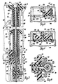
- a radio antenna 10 is shown which is adapted for mounting in an interior space of a vehicle body underneath, for example, a front bumper or rear quarter panel member or other suitable surface 12.
- the attachments to the vehicle body include one or more brackets 14 for a lower housing portion, and an upper ball-like mounting assembly 16, described below which, secure an upper end of the radio antenna 10 in an aperture 18 of the surface 12.
- the radio antenna 10 is constructed of a plurality of easily integrated subassemblies or subunits including a mast tubes unit 20, a motor drive unit 22 and a storage drum unit 24, all assembled within a housing 26.
- the housing 26 is preferably prefabricated of die cast aluminium or similar light weight metallic material providing a relatively deep rectangular cavity for receiving the mast tubes unit 20, the motor drive unit 22 and the storage drum unit 24.
- the mast tubes unit 20 is received within open-ended slots 28 in the top and an adjacent side wall of the housing 26 and held therein by grommets 30 and 32 each captured in the edges of the respective open-ended slot 28 and fabricated of suitable polymeric material exhibiting substantial dielectric or electrically insulative properties.
- the grommet 32 in the open-ended slot 28 in the side wall is, as seen best in Figure 6, further constructed with an embedded metallic retainer 34 having flanges 36 which may be crimped over ears 40 of a retainer sleeve 38 welded to the lower portion of the mast tubes unit 20.
- the ears 40 further capture suitable flanges of a metallic retainer 41 of a tubular RF cable connector.
- the motor drive unit 22 comprises a motor frame, not shown in detail, suitably affixed to an interior wall of the housing 26 to one side of the mast tubes unit 20.
- the motor of the motor drive unit 22 is preferably of the permanent magnet type, reversible in operation and the drive shaft of which carries a pulley 42 connected by an endless belt 44 to a drive nut 46 suitably rotatably mounted in plastics bearings 47 on the motor frame of the motor drive unit 22 directly beneath the end of the mast tubes unit 20.
- the storage drum unit 24 comprises a cover and guide member 48 with a flat body portion 50 which is apertured in various locations for attachment by screws to underlying supporting ribs 52 cast into walls of the housing 26, as seen best in Figures 4 and 5.
- the cover and guide member 48 includes an integral depending stem 54 received within a centrally bored boss 56 of the housing 26. Also, reverting to Figure 2, the integral depending stem 54 rotatably mounts underneath the cover and guide member 48 a cable drum 58 of moulded construction having a series of angularly spaced webs 60 radiating from its central hub to an enlarged cable-receiving annular portion 62 having a deep cavity partially defined by a cylindrical outer drum wall 64.
- Both the cable drum 58 and the cover and guide member 48 are fabricated of a suitable electrically insulative material such as medium impact polypropylene.
- a housing cover 66 which may again be constructed of cast aluminium or sheet steel, or of a metallized polymeric construction which may preferably have integrally formed retainer tabs that snap over outer edges of the housing 26 for cover retention.
- the mast tubes unit 20 contains sheath tubes fabricated of a tough but flexible polymer that will withstand impact or continuous stress from engagement with such hazards as garage doors, auto wash mechanisms and the like.
- the sheath tubes comprise an innermost sheath 68 and intermediate and outer sheaths 70 and 72.
- a preferred material for these sheath tubes is a fiberglass reinforced thermoset polymer having a filament wound construction.
- the upper end of each sheath tube is preferably moulded with an inturned shoulder, such as shoulder 68a...
- the shoulder 68a may be provided by insertion and bonding of a short plastic sleeve in the otherwise continuous diameter or if desired, slightly tapered, sheath stock.
- a lower shoulder configuration on the sheath tubes comprise successively overlapping sheet metal cups bonded or staked over the lower end of each successive larger tube, as for example smallest cup 68b on the lower end of the innermost sheath 68.
- An inner antenna rod 74 of stainless steel is received telescopically within the innermost sheath 68 and is threaded at its upper end to receive a conventional finial 76. Adjacent its lower end, the inner antenna rod 74 is welded or otherwise secured within a central bore of a coupling sleeve 78 of stainless steel or like material. Upon extension of the radio antenna 10 to a deployed position above the surface 12, the upper end of the coupling sleeve 78 will move upwardly to strike the shoulder 68a of the innermost sheath 68 and further such extension of the inner antenna rod 74 upwardly will successively engage the opposed shoulders of the remaining sheath tubes until the mast tubes unit 20 reaches the fully extended and,deployed position represented in Figure 2.
- inward retraction of the inner antenna rod 74 causes the finial 76 to engage the upper end of the innermost sheath 68 followed by successive engagement of the successively overlapped lower cups 68b etc. and continued motion until the mast tubes unit 20 is fully retracted.
- the inner antenna rod 74 and the sheath tubes of the mast tubes unit 20 are adapted for nesting within a large diameter shield tube 80, the lower end of which is attached to the retainer sleeve 38.
- Both the shield tube 80 and the retainer sleeve 38 are fabricated of steel or like metal to serve as a barrier to electromagnetic radiation when properly grounded.
- an upper sleeve 82 of die cast zinc or the like at the upper end of the shield tube 80 there is affixed by staking, screws, or the like an upper sleeve 82 of die cast zinc or the like and either the upper sleeve 82 or the upper end of the shield tube 80 is connected by a ground strap 84 to the surface 12 or adjacent vehicle body sheet metal structure at ground potential within the vehicle body.
- a similar ground strap 86 connection is provided between the lower end of the shield tube 80 and a wall of the housing 26, Figure 2.
- any number of suitable attachment means at the surface 12 are acceptable for the upper end of the upper sleeve 82, but in a preferred embodiment the upper extremity of the upper sleeve 82 is formed spherically for push-in assembly within a socket-like cavity of a polymeric mounting member 88 suitably secured to the surface 12, whereby the radio antenna 10 is easily oriented in various attitudes relative to the surface 12 as required while secured therewithin by the brackets 14.
- the upper ball-like mounting assembly 16 further comprises an insulator sleeve 90 of polymeric material joined as by threads to the ball portion of the upper sleeve 82 and having close sealing engagement, as at plastic ring 91, with the outer sheath 72 to prevent ingress of moisture, etc.
- a stationary tube 92 of electrically insulative polymer material extends from the insulator sleeve 90 protectively over the assembly of sheath tubes throughout the length of the shield tube 80.
- the mast tubes unit 20 further comprises a lower sleeve 96 of relatively thick polymeric material with substantial electrically insulative properties, such as medium impact polypropylene.
- the lower sleeve 96 serves to mount a cable guide and radio frequency cable connector assembly.
- the axis of the shield tube 80 defines an operative axis for extension and retraction of the radio antenna by use of a cable assembly 100 which serves not only as an actuating drive element but also as the radio wave collector or receptor.
- the cable assembly 100 has been found to be best constructed of a multiple layer of steel wire including a monofilamentary wire or core of high tensile steel with a brass coating, and a series of helically wrapped additional such wire layers, all for the purpose of providing a tough actuating cable assembly that will withstand repeated sequences of powered radio antenna extension and retraction in the severely varied weather conditions to which automobiles ⁇ are typically subjected. Yet, the cable assembly 100 must be sufficiently flexible to withstand impacts or force from engagement of such hazards, as garage doors, etc.
- the cable assembly 100 exhibit a substantial self-sustaining stiffness or elevated elastic modulus so as, when deployed as an radio antenna, to maintain its normally straight form even in moderate winds, and when so wound on the cable drum 58, as will be described, to exhibit significant uncoiling force.
- the centre core wire is of 0.3mm diameter and a first helical wrap thereover comprises four strands or starts of individual brass coated high-tensile steel wire laid helically side by side with a pitch of 1.7mm, the diameter of each start or strand being 0.3mm.
- a second helical wrap 102 again comprises four wire strands or starts of 0.3mm of high tensile brass-coated steel wire helically wound side by side in a layer having the opposite helical hand to the first helical wrap.
- a larger pitch single wire helical overlayer 104 is made in the same helical hand as the first helical wrap, and which is of a larger diameter (1.0mm) high tensile uncoated steel wire structure laid with a helix pitch of 2.5mm.
- a brass coating may be avoided in favour of the surface application thereto of suitable electrically conductive molybdenum filled grease.
- the upper end of the cable assembly 100 is welded or otherwise affixed within the bore of the lower end of the coupling sleeve 78 on the inner antenna rod 74, Figure 3, thus constructing a cable and rod unit serving as the radio wave receptor.
- the cable assembly 100 is received for meshed engagement within the helically grooved central bore of the drive nut 46, and for this purpose the drive nut is aligned on the operative axis for the cable assembly 100 defined by the shield tube 80.
- the helical grooving of the drive nut 46 is closely diametrically sized to and matches the helical pitch of the single wire helical overlayer 104 of the cable assembly 100, again as seen best in Figure 3.
- the drive nut 46 is fabricated of an electrically insulative thermoplastic polymer such as polyester and as seen in Figure 3, includes a pair of axial extensions 105 journaled in the two plastic bearings 47 supported on the motor drive unit 22.
- the drive nut 46 and the endless belt 44 (of elastomeric material) provide no direct path for electromagnetic disturbances to the cable assembly 100, nor any appreciable capacitive coupling of the cable assembly with the adjacent metallic structure.
- the cable assembly 100 further extends along the operating axis of the shield tube 80 to enter a tapered entrance guide bore 108 moulded within a raised portion 106 of the cover and guide member 48 and aligned on the operating axis upon installation of the latter in the housing 26.
- the tapered entrance guide bore 108 gradually deviates from the operating axis downwardly ( Figure 4) toward, and opens into, the cylindrical cavity of the cable drum 58 whereby to direct movement of the cable assembly 100 to and from a coiled configuration within the cable drum.
- the lower sleeve 96 and the tapered entrance guide bore 108 of the raised portion 106 serve as spaced guide elements of electrically-insulative material situated on the operating axis of the shield tube 80 for directing translation of the cable assembly 100 therethrough from the coiled condition of Figure 1 to the substantially uncoiled and extended condition of Figure 2, and vice versa.
- This guidance arrangement prolongs the life of the cable assembly 100 in service.
- This translation of the cable assembly 100 is achieved by selected powered rotation in opposite directions of the drive nut 46 by the motor drive unit 22, such being accomplished by conventional power switching integrated in the radio receiver.
- a Hall probe device be integrated with the pulley 42 of the motor drive unit 22 either to precisely count the rotations of the drive nut 46 between the radio antenna 10 extended and retracted positions, or sense stall thereof, and automatically halt the motor.
- the radio reception element embodied in the cable assembly 100 may effectively direct the received radio waves to an RF cable and radio receiver via a single contact point.
- a combined cable guide and contact ferrule 110 there is provided within the central bore of the lower sleeve 96 a combined cable guide and contact ferrule 110, seen best in Figures 3 and 6. It is essentially of tubular construction, including a first portion 112 of a diameter sized closely to the single wire helical overlayer 104 of the cable assembly 100 and including lanced inwardly bowed contact strips 114.
- the cable guide and contact ferrule 110 is aligned on the operating axis defined by the shield tube 80 and acts as the cable guide at the lower end of the shield tube.
- the cable guide and contact ferrule 110 further includes a terminal portion 116 bent at a right angle from the first portion 112, again of tubular form, and mated with a female connector end 118 of a conventional coaxial (RF wire and ground sheath) cable assembly integrated with the grommet 32.
- the female connector end 118 is conventionally fitted with a conductive outer shell element on its ground sheath which is placed in contact with the grounded metallic retainer 41 connected to the shield tube 80.
- the radio reception performance of the radio antenna 10 derives maximum benefits from the organization of the elements hereinabove described.
- the first portion 112 itself is of substantially the diameter of the cable assembly 100 and substantially smaller than the shield tube 80, with only slight flaring at its ends 115 to aid in the operations of the cable assembly 100.
- Capacitive coupling with the shield tube 80 is thereby avoided, that is, the ratio of the diameters of the two elements prohibits the shield tube 80 itself acting effectively as a receptor in conjunction with the cable assembly 100.
- the shield tube 80 while maintained at ground potential, is distant and isolated from the cable assembly 100 by substantial thickness of insulative media including the upper and lower insulative sleeves 90, 96, the sheath tubes, and the stationary tube 92.
- the housing 26 and the housing cover 66 when assembled with the shield tube 80 effectively shield the entire length of the cable assembly 100 from ambient electromagnetic radiation except for that portion thereof deployed above the surface 12.
- the length of such portion together with the inner antenna rod 74 has generally been found to require 1 meter of effective length.
- the remainder of the cable assembly 100 situated below the ground plane of the surface 12 may, depending on various car styles, be of substantial additional length but does not constitute an undesirable receptor either by direct unshielded exposure to such radiation or subject to capacitive coupling with those elements which are grounded as aforementioned.
Landscapes
- Details Of Aerials (AREA)
Applications Claiming Priority (2)
| Application Number | Priority Date | Filing Date | Title |
|---|---|---|---|
| US06/822,484 US4742360A (en) | 1986-01-27 | 1986-01-27 | Power antenna |
| US822484 | 1992-01-17 |
Publications (2)
| Publication Number | Publication Date |
|---|---|
| EP0235873A2 true EP0235873A2 (de) | 1987-09-09 |
| EP0235873A3 EP0235873A3 (de) | 1988-12-21 |
Family
ID=25236155
Family Applications (1)
| Application Number | Title | Priority Date | Filing Date |
|---|---|---|---|
| EP87300052A Withdrawn EP0235873A3 (de) | 1986-01-27 | 1987-01-06 | Streckbare Rundfunkantenne |
Country Status (3)
| Country | Link |
|---|---|
| US (1) | US4742360A (de) |
| EP (1) | EP0235873A3 (de) |
| JP (1) | JPS62189802A (de) |
Cited By (2)
| Publication number | Priority date | Publication date | Assignee | Title |
|---|---|---|---|---|
| WO1997045891A1 (en) * | 1996-05-30 | 1997-12-04 | Qualcomm Incorporated | Telescoping mast antenna for wireless devices |
| EP2405280A3 (de) * | 2010-07-09 | 2014-01-22 | Milwaukee Electric Tool Corporation | Beleuchtungstester |
Families Citing this family (15)
| Publication number | Priority date | Publication date | Assignee | Title |
|---|---|---|---|---|
| JPH01140801A (ja) * | 1987-11-27 | 1989-06-02 | Nippon Antenna Kk | 電動アンテナ伸縮操作機構 |
| JPH03285402A (ja) * | 1990-03-31 | 1991-12-16 | Aisin Seiki Co Ltd | 自動車用アンテナ装置 |
| US5166695A (en) * | 1991-07-15 | 1992-11-24 | Motorola, Inc. | Auto-extending antenna |
| US5485170A (en) * | 1993-05-10 | 1996-01-16 | Amsc Subsidiary Corporation | MSAT mast antenna with reduced frequency scanning |
| USD387355S (en) * | 1995-03-20 | 1997-12-09 | Harada Industry Co., Ltd. | Antenna assembly |
| US5995066A (en) * | 1996-06-25 | 1999-11-30 | Chrysler Corporation | One piece mast power antenna having electrical contact with sliding and docking contact portions |
| JPH10303620A (ja) * | 1997-04-22 | 1998-11-13 | Harada Ind Co Ltd | 自動車用電動アンテナ装置 |
| DE19919107A1 (de) * | 1999-04-27 | 2000-11-16 | Siemens Ag | Mobile Funk-Sende-/Funk-Empfangseinrichtung mit abstimmbarer Antenne |
| US20070089663A1 (en) * | 2005-10-26 | 2007-04-26 | Dan Dunbar | Semaphore apparatus |
| US7522111B2 (en) * | 2007-08-15 | 2009-04-21 | Uniden America Corporation | Telescoping antenna with retractable wire antenna element |
| US9160392B2 (en) * | 2014-01-23 | 2015-10-13 | Harris Corporation | Rotary knob with integrated antenna |
| US10784560B1 (en) * | 2019-01-03 | 2020-09-22 | Enrique J. Baiz | Vehicle antenna with anti-theft feature |
| US10819003B1 (en) * | 2019-01-03 | 2020-10-27 | Enrique J. Baiz | Customizable radio antenna |
| USD951924S1 (en) | 2020-11-24 | 2022-05-17 | Enrique J Baiz | Vehicle antenna |
| US20220409885A1 (en) * | 2021-06-23 | 2022-12-29 | Pacesetter, Inc. | Biostimulator delivery system having tether cable |
Family Cites Families (8)
| Publication number | Priority date | Publication date | Assignee | Title |
|---|---|---|---|---|
| US2299785A (en) * | 1940-05-16 | 1942-10-27 | Barrett Engineering Company | Radio antenna |
| US2346728A (en) * | 1941-10-20 | 1944-04-18 | Carlson Emil | Power driven operating means for extensible and retractable aerials |
| US2514167A (en) * | 1945-05-28 | 1950-07-04 | Shakespeare Products Co | Radio antenna |
| US2491601A (en) * | 1946-11-20 | 1949-12-20 | Bernstein Irving | Extensible car radio antenna |
| US2926351A (en) * | 1955-04-26 | 1960-02-23 | Anderson Co | Power-operated antenna |
| US2953934A (en) * | 1958-04-28 | 1960-09-27 | Sundt Edward Victor | Mechanism for operating telescopic antennas or the like |
| US4128965A (en) * | 1977-06-06 | 1978-12-12 | Hondt August J D | Plant stake |
| DE3338511A1 (de) * | 1983-10-22 | 1985-05-02 | Robert Bosch Gmbh, 7000 Stuttgart | Durch einen elektromotor ein- oder ausfahrbare teleskopantenne |
-
1986
- 1986-01-27 US US06/822,484 patent/US4742360A/en not_active Expired - Fee Related
-
1987
- 1987-01-06 EP EP87300052A patent/EP0235873A3/de not_active Withdrawn
- 1987-01-27 JP JP62015328A patent/JPS62189802A/ja active Pending
Cited By (3)
| Publication number | Priority date | Publication date | Assignee | Title |
|---|---|---|---|---|
| WO1997045891A1 (en) * | 1996-05-30 | 1997-12-04 | Qualcomm Incorporated | Telescoping mast antenna for wireless devices |
| EP2405280A3 (de) * | 2010-07-09 | 2014-01-22 | Milwaukee Electric Tool Corporation | Beleuchtungstester |
| US8970220B2 (en) | 2010-07-09 | 2015-03-03 | Milwaukee Electric Tool Corporation | Lighting tester |
Also Published As
| Publication number | Publication date |
|---|---|
| EP0235873A3 (de) | 1988-12-21 |
| JPS62189802A (ja) | 1987-08-19 |
| US4742360A (en) | 1988-05-03 |
Similar Documents
| Publication | Publication Date | Title |
|---|---|---|
| US4742360A (en) | Power antenna | |
| US4375642A (en) | Rod antenna, particularly for mobile FM signal transducing applications | |
| WO1987000351A1 (en) | Axial multipole mobile antenna | |
| US2299785A (en) | Radio antenna | |
| US4117495A (en) | Self-tuning deployable antenna | |
| JP2567384B2 (ja) | 多帯域アンテナ | |
| EP2736135B1 (de) | Kabelbaum | |
| EP0951748A2 (de) | Einziehbare trommel mit kanälen versehenem sperrklinkenmechanismus | |
| US20080093030A1 (en) | Awning assembly including drop-down shade | |
| US2366634A (en) | Antenna | |
| US3254344A (en) | Removable telescopic antenna | |
| US5184142A (en) | Automotive vehicle antenna | |
| US5414436A (en) | Electric extensible car antenna | |
| US5451974A (en) | Retractable helical antenna | |
| US2341401A (en) | Radio antenna | |
| US3253799A (en) | Reel for extending and retracting a flexible cable actuator | |
| US4325069A (en) | Convertible telescopic antenna | |
| CA1241437A (en) | Extendable directional dipole antenna | |
| JP2570762Y2 (ja) | 電気導体収容装置を備えた機器 | |
| KR19980703653A (ko) | 안테나 | |
| CN1333937A (zh) | 小型的可收放电缆卷盘 | |
| US4633266A (en) | Electrically projectable telescopic rod antenna, particularly for automotive installation | |
| US2870973A (en) | Driving mechanism for retractable antennae | |
| US4393383A (en) | Mobile antenna mounting assembly | |
| US5995066A (en) | One piece mast power antenna having electrical contact with sliding and docking contact portions |
Legal Events
| Date | Code | Title | Description |
|---|---|---|---|
| PUAI | Public reference made under article 153(3) epc to a published international application that has entered the european phase |
Free format text: ORIGINAL CODE: 0009012 |
|
| 17P | Request for examination filed |
Effective date: 19870115 |
|
| AK | Designated contracting states |
Kind code of ref document: A2 Designated state(s): DE FR GB IT SE |
|
| PUAL | Search report despatched |
Free format text: ORIGINAL CODE: 0009013 |
|
| AK | Designated contracting states |
Kind code of ref document: A3 Designated state(s): DE FR GB IT SE |
|
| 17Q | First examination report despatched |
Effective date: 19901109 |
|
| STAA | Information on the status of an ep patent application or granted ep patent |
Free format text: STATUS: THE APPLICATION IS DEEMED TO BE WITHDRAWN |
|
| 18D | Application deemed to be withdrawn |
Effective date: 19910403 |
|
| RIN1 | Information on inventor provided before grant (corrected) |
Inventor name: WILDER, WINSTON CHURCHILL Inventor name: CAROLUS, DAVID THOMAS Inventor name: EVANS, ROBERT EDWARD |