EP0236100B1 - Cassette pour disques - Google Patents
Cassette pour disques Download PDFInfo
- Publication number
- EP0236100B1 EP0236100B1 EP87301780A EP87301780A EP0236100B1 EP 0236100 B1 EP0236100 B1 EP 0236100B1 EP 87301780 A EP87301780 A EP 87301780A EP 87301780 A EP87301780 A EP 87301780A EP 0236100 B1 EP0236100 B1 EP 0236100B1
- Authority
- EP
- European Patent Office
- Prior art keywords
- shutter
- lower side
- side plates
- thickness
- disc cartridge
- Prior art date
- Legal status (The legal status is an assumption and is not a legal conclusion. Google has not performed a legal analysis and makes no representation as to the accuracy of the status listed.)
- Expired - Lifetime
Links
Images




Classifications
-
- G—PHYSICS
- G11—INFORMATION STORAGE
- G11B—INFORMATION STORAGE BASED ON RELATIVE MOVEMENT BETWEEN RECORD CARRIER AND TRANSDUCER
- G11B23/00—Record carriers not specific to the method of recording or reproducing; Accessories, e.g. containers, specially adapted for co-operation with the recording or reproducing apparatus ; Intermediate mediums; Apparatus or processes specially adapted for their manufacture
- G11B23/02—Containers; Storing means both adapted to cooperate with the recording or reproducing means
- G11B23/03—Containers for flat record carriers
- G11B23/033—Containers for flat record carriers for flexible discs
- G11B23/0332—Containers for flat record carriers for flexible discs for single discs, e.g. envelopes
-
- G—PHYSICS
- G11—INFORMATION STORAGE
- G11B—INFORMATION STORAGE BASED ON RELATIVE MOVEMENT BETWEEN RECORD CARRIER AND TRANSDUCER
- G11B23/00—Record carriers not specific to the method of recording or reproducing; Accessories, e.g. containers, specially adapted for co-operation with the recording or reproducing apparatus ; Intermediate mediums; Apparatus or processes specially adapted for their manufacture
- G11B23/02—Containers; Storing means both adapted to cooperate with the recording or reproducing means
- G11B23/03—Containers for flat record carriers
- G11B23/0301—Details
- G11B23/0308—Shutters
Definitions
- This invention relates to a disk cartridge encasing such a disk as a magnetic disk, an optical disk, etc, and more particularly to an improvement of materials for a shutter to be provided on the outside of a cartridge case to open or close head insert openings of the cartridge case.
- the shutters so far used are made from a thin stainless steel sheet and have a U-shaped cross-section.
- the shutters have an opening substantially the same shape as that of the head insert openings, engaging lugs for preventing the shutter from slipping out of the case, a spring-fixing lug, etc. on the shutter side plates.
- the metallic shutters have no problem with respect to their strength, but are liable to scrape the plastic cartridge case surface through contact with the peripheral edge, lugs, etc. of the shutters, and the scrapings are liable to fall into the cartridge case and deposit onto the disk or head, causing a dropout, etc.
- shutters molded from plastics have been proposed (for example, Japanese Patent Application Kokai (laid-open) No. 60-231985 and EP-A-0 160 538 which provides the basis for the prior art portion of claim 1), where the upper side plate and the lower side plate, which are juxtaposed to each other in the case thickness direction, and an end plate connected to the upper and lower side plates at one end are integrally molded by injection molding.
- a thin stainless steel sheet thickness: 0.2 - 0.3 mm
- the thin stainless steel sheet can satisfy requirements for strength, such as mechanical strength, wearing resistance, etc. and requirements for smaller sizes and smaller thickness at the same time, and further that it undergoes no rusting and thus can give an aesthetic merit.
- it is desirable that a shutter made from plastics must also satisfy the similar structural and functional requirements.
- the most important problem in the molding technique resides in the extremely thin upper and lower side plates constituting a shutter, and the large area of the side plates, as compared with the plate thickness.
- the molten resin cannot be uniformly and surely extended throughout the molding space, for example, even by elevating the pouring pressure to a considerable degree, since the surface area is too large.
- the distance between the upper and lower side plates is as small as 2 - 3 mm, the core placed between the upper and lower side plates to partition one off another cannot be cooled. That is, there is another problem that mold cooling cannot be carried out uniformly.
- the present invention has been made in the foregoing technical backgrounds and an object of the present invention is to provide a plastic shutter having a good mechanical strength, capable of being molded on a mass-production scale with a good moldability.
- the present invention has found that by using a plastics material having a higher melt index than usual so that it is more fluid it is possible to incorporate a filler and still be able to form accurately the thin side plates of the shutter with such side plates not only having an adequate strength and resistance to heat but also an acceptable slidability.
- the filler for use in the present invention is selected from materials in a granular, whisker or plate shape, incapable of melting at the moulding temperature such as calcium carbonate, potassium titanate, silica, talc, etc and 5 to 20% by weight, preferably 10 to 20% by weight of the filler is contained in the composite plastic.
- the molded article will have a poor heat resistance and is liable to undergo deformation at a temperature of 60 o C, also showing a poor mechanical strength and easy breakage, whereas above 30% by weight, the molten compound plastic will have poor flowability and a poor moldability.
- the wide range of the mixing ratio of the lubricant is ascribable to differences in the characteristics of the individual lubricants, and is based on the requirements for equivalent or superior mold release characteristics and lubricity of a shutter to those of the metallic shutter. Above 10% by weight of the lubricant, the mechanical strength of the shutter will be lowered. Thus, the mixing ratio of the lubricant can be not more than 10% by weight.
- a shutter comprises an upper side plate 21 , a lower side plate 22 having substantially the same shape as that of the upper side plate 21 , the upper and lower side plates 21 and 22 being juxtaposed at a small distance, and an end plate 23 connected to the upper and lower side plates 21 and 22 at one end, showing a U-shaped cross-section.
- the thickness of the end plate 23 has somewhat more degree of freedom than that of the upper and lower side plates, and can be made larger. That is, a pouring gate for the molten composite plastic can be provided at a plurality of locations on the end plate.
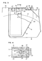
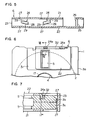
- Fig. 1 to Fig. 5 shows a shutter for a disk cartridge according to a first application embodiment of the present invention, where Fig. 1 is a plan view, Fig. 2 is a bottom view, Fig. 3 is a partly cutaway plan view of the essential part showing a shutter and its neighborhood structure, Fig. 4 is a cross-sectional view along the line IV - IV of Fig. 3, and Fig. 5 is a cross-sectional front view of the essential part showing engaging lugs of the shutter.
- Fig. 6 and Fig. 7 mainly show a shutter for a disk cartridge according to a second application embodiment of the present invention, where Fig. 6 is a bottom view of the essential part of the shutter and its neighborhood structure and Fig. 7 is a cross-sectional view along the line VII - VII of Fig. 6.
- Fig. 8 and Fig. 9 mainly show a shutter for a disk cartridge according to a third application embodiment of the present invention, where Fig. 8 is a plan view of the essential part and Fig. 9 is a cross-sectional view along the line IX - IX of Fig. 8.
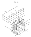
- Fig. 10 to Fig. 12 show schematic structures of a mold for molding shutter according to the present invention, where Fig. 10 is a perspective view of a disassembled mold, Fig. 11 is a cutaway front view of the essential part of the mold, and Fig. 12 is a vertical cross-sectional view of the mold.
- the lower shell 3b further has insert holes 8 for a positioning pin, an operational groove for operating a light protect notch 9 and a recess 12 for pasting a label, as shown in Fig. 1.
- Cleaning members 13 capable of sandwiching the disk 2 through liner sheets not shown in the drawings are provided on the inside surfaces of the upper and lower shells 3a and 3b at a position on the disk-coming side in the disk rotating direction as viewed from the head insert openings 5 . These cleaning members 13 are supported from the outside of the case through operational openings 14a and 14b provided through the walls of the upper and lower shells 3a and 3b to make cleaning of the disk 2 and prevent the flapping of a magnetic sheet 16 as driven.
- the disk 2 is composed of a circular magnetic sheet 16 and a hub 17 facing the said driving shaft insert opening 4 as fixed at the center of the magnetic sheet 16 .
- the hub 17 is composed of a flange 17a made from a thin magnetic stainless steel sheet and a boss 17b as outsert fixed thereto.
- the magnetic sheet 16 is fixed to the flange 17a by adhesion.
- the boss 17b has a chevron-shaped positioning part 18 for concentrically positioning the entire disk with respect to the driving shaft of the disk drive, whereas the flange 17a has a driving hole 19 with which a driving pin is engaged.
- Main dimensions of shutter 6 applicable to the disk cartridge of 2.5-inch nominal size shown in Figs. 1 to 5 are as follows: Length: 24.4 mm Maximum width: 19.5 mm Thickness each of the upper and lower side plates 21 and 22 : 0.35 mm Distance between the upper and lower side plates 21 and 22 (inner face basis): 2.1 mm Area each of the upper and lower side plates 21 and 22 : about 412 mm2 Area of the end plate 23 : 55 mm2 Depth of the pocket 31 : 0.5 mm
- a third application embodiment of the disk cartridge (nominal size: 5 inches) is shown, where a pair of engaging lugs 24b are projected from the inside surface of the end plate 23 .
- the engaging lug 24b comprises a lug arm 28b and a lug head 29b downwardly projected from the end of the lug arm 28b .
- Slip-out prevention and slide guiding of the shutter 6 can be carried out by engaging the lug head 29b with an engaging rib 33b projected from the lower shell 3b .
- the mold provides a basic form of cavity 45 by a cover mold 40 whose plane along the outer surface of the end plate 23 of the shutter 6 serves as a mold portion face, a movable mold 41 , and a pair of slide cores 42 and 43 surrounding the movable core 41 from the mutually opposite directions.
- the cover mold 40 has a sprue runner 47 .
- the movable mold 41 has a core 41a corresponding to the inner surface shape of the shutter 6 .
- the core 41a has a trapezoidal cross-section so that the thickness of the core 41a may be larger towards its lower end, that is, towards the free ends of the upper and lower side plates 21 and 22 than the distance between the upper and lower side plates 21 and 22 of the shutter 6 as a base dimension.
- pairs of slide cores 48 and 48 are further provided.
- the slide cores 48 are wider than the engaging lugs 24 and sandwich and fix the upper end of the core 41a of the movable mold 41 from both sides by both ends of the slide cores 48 in their width direction to hold the thin core in the normal position.
- the thickness of the upper and lower side plates 21 and 22 can be correctly controlled thereby.
- the outer surface shapes of the upper and lower side plates 21 and 22 of the shutter 6 are defined by the slide cores 42 and 43 counterposed to each other at the core 41a , and the shape of the end plate 23 is defined by the cover mold 40 and the movable mold 41 .
- a cavity 50 for gate is formed between the cover mold 40 and the movable mold 41 , as connected to the cavity for forming the end plate 23 , and is communicated with the sprue runner 47 . That is, the cavity 50 for gate is positioned, as extended along and over the molding space for the end plate 23 , to guide a molten resin from the sprue runner 47 into the cavity 45 for molding the product.
- the cavity 50 for gate having a gate function, as extended over both ends of the cavity 45 for molding the product and directly communicating the cavity 50 for gate with the sprue runner 47 , a pressure drop between the terminals of the sprue runner 47 and the cavity 45 can be reduced during the molding of the shutter 6 , and the shutter 6 of U-shaped cross-section having a very small plate thickness as compared with the plate surface area can be molded with a higher reliability.
- the cavity 50 for gate can be used for knockout purpose, and the molded article can be released from the mold by taking the solidified resin off the cavity 50 for gate with a releasing pin.
- the shutter 6 as a product can be obtained by cutting the unnecessary parts off the molded article.
- Example 1 In the material No. 3 of Example 1, the mixing ratio and the particle size of calcium carbonate were changed as shown in Table 2, and shutters 6 were molded therefrom in the same manner as in Example 1.
- Example 1 In the material No. 3 of Example 1, zinc stearate was added in place of stearic acid, while changing its mixing ratio as shown in Table 7. Shutters 6 were molded therefrom in the same manner as in Example 1. Table 7 Zinc stearate (wt.%) 0.1 0.5 1 5 10 Material No. 46 47 48 49 50
- Heat resistance was determined by heat resistance test according to JIS K-7207.
- Slidability was determined by mounting the shutter 6 onto the case 1 , setting the shutter 6 in the closed position by the force of the spring 7 having a given small tension, then moving the shutter 6 to the open position, and making the shutter 6 reset therefrom to the closed position, while investigating the resetting behavior to the closed position through comparison.
Landscapes
- Moulds For Moulding Plastics Or The Like (AREA)
Claims (5)
- Cassette pour disques, comprenant un boîtier (1) ayant des ouvertures (5) pour l'introduction de têtes et un volet (6) moulé à partir d'une matière plastique et ayant une section transversale en forme de U, le volet (6) étant placé sur le boîtier de manière à coulisser sur le boîtier pour ouvrir et fermer les ouvertures d'introduction de têtes, le volet comprenant une paire de plaques latérales supérieure et inférieure (21, 22) ayant sensiblement la même forme et en juxtaposition, et une plaque d'extrémité (23) reliée aux plaques latérales supérieure et inférieure à une extrémité, les plaques latérales supérieure et inférieure ayant chacune une épaisseur ne dépassant pas 1,0 mm et une valeur de l'épaisseur, mesurée en mm, divisée par la surface, mesurée en mm², des plaques latérales supérieure et inférieure chacune située entre 1/5000 et 1/500, caractérisée en ce que la matière plastique comprend le polyacétal, le nylon, le polybutylène-téréphtalate, le polyester, le polypropylène, le polyéthylène ou le polyfluoroéthylène ayant un indice de fusion selon ASTM D-1238 de 30 à 60 et contenant de 5 à 20 % en poids d'un matériau d'apport, le matériau d'apport étant lui-même un matériau de renforcement qui est incapable de fondre à la température de moulage et qui a une taille des particules au-dessous d'une valeur prédéterminée, par exemple du carbonate de calcium avec une dimension granulométrique inférieure à 5 µm, ou du titanate de potassium avec un diamètre de fibre moyen de 0,3 µm et une longueur de fibre moyenne de 10 à 20 µm.
- Cassette pour disques selon la revendication 1, dans laquelle la matière du volet comprend de 0,1 à 10 % en poids d'un lubrifiant.
- Cassette pour disques selon la revendication 2, dans laquelle la matière plastique comprend de 0,5 % à 2,0 % en poids du lubrifiant.
- Cassette pour disques selon l'une quelconque des revendications précédentes, dans laquelle la valeur de l'épaisseur, mesurée en mm, divisée par la surface, mesurée en mm², de la plaque se situe dans la plage de 1/4000 à 1/1000.
- Cassette pour disques selon l'une quelconque des revendications précédentes, dans laquelle la matière plastique comprend de 10 à 20 % du matériau d'apport.
Applications Claiming Priority (2)
| Application Number | Priority Date | Filing Date | Title |
|---|---|---|---|
| JP61044891A JPH0740423B2 (ja) | 1986-03-01 | 1986-03-01 | デイスクカ−トリツジ |
| JP44891/86 | 1986-03-01 |
Publications (2)
| Publication Number | Publication Date |
|---|---|
| EP0236100A1 EP0236100A1 (fr) | 1987-09-09 |
| EP0236100B1 true EP0236100B1 (fr) | 1993-07-28 |
Family
ID=12704103
Family Applications (1)
| Application Number | Title | Priority Date | Filing Date |
|---|---|---|---|
| EP87301780A Expired - Lifetime EP0236100B1 (fr) | 1986-03-01 | 1987-02-27 | Cassette pour disques |
Country Status (4)
| Country | Link |
|---|---|
| US (2) | US4849844A (fr) |
| EP (1) | EP0236100B1 (fr) |
| JP (1) | JPH0740423B2 (fr) |
| DE (1) | DE3786684T2 (fr) |
Families Citing this family (41)
| Publication number | Priority date | Publication date | Assignee | Title |
|---|---|---|---|---|
| JPH0740424B2 (ja) * | 1986-11-06 | 1995-05-01 | ソニー株式会社 | デイスクカセツト |
| GB2208330B (en) * | 1987-07-27 | 1991-12-04 | Hitachi Ltd | An optical disc cartridge and a mechanism for preventing an incorrect insertion of a cartridge. |
| JP2505214B2 (ja) * | 1987-09-11 | 1996-06-05 | 日立マクセル株式会社 | デイスクカ―トリツジ |
| KR0124147B1 (ko) * | 1987-07-29 | 1997-11-28 | 나가이 아쯔시 | 디스크 카트리지 |
| US4991048A (en) * | 1987-10-15 | 1991-02-05 | Tdk Corporation | Disc cartridge casing with shutter slidably fitted therein to uncover a pick-inserting hole |
| JPH01151474U (fr) * | 1988-04-08 | 1989-10-19 | ||
| DE68929036T2 (de) * | 1988-04-28 | 1999-11-11 | Dai Nippon Insatsu K.K., Tokio/Tokyo | Plattenkassette |
| US5289457A (en) * | 1988-04-28 | 1994-02-22 | Dai Nippon Insatsu Kabushiki Kaisha | Disc cartridge with bent spring design for closing a closure shutter |
| US5237560A (en) * | 1988-06-23 | 1993-08-17 | Mitsubishi Denki Kabushiki Kaisha | Optical disc cartridge |
| DE68918195T2 (de) * | 1988-07-26 | 1995-03-16 | Hitachi Maxell | Verschlussschieber einer Plattenkassette, Vorrichtung und Verfahren zur dessen Herstellung. |
| JPH0283876A (ja) * | 1988-09-20 | 1990-03-23 | Hitachi Maxell Ltd | デイスクカートリツジ |
| USD312077S (en) | 1988-10-11 | 1990-11-13 | Next, Inc. | Computer disk cartridge |
| USD312250S (en) | 1988-10-11 | 1990-11-20 | Next, Inc. | Computer disk cartridge |
| JPH0268378U (fr) * | 1988-11-11 | 1990-05-23 | ||
| US5021913A (en) * | 1989-04-24 | 1991-06-04 | Overland Bolling Company | Shutter for covering a window opening in a case that contains a flexible disk |
| JP2961816B2 (ja) * | 1989-06-05 | 1999-10-12 | ソニー株式会社 | ディスクカートリッジ |
| JP2827332B2 (ja) * | 1989-10-06 | 1998-11-25 | ソニー株式会社 | ディスクカートリッジ |
| JP2818451B2 (ja) * | 1989-10-20 | 1998-10-30 | ポリプラスチックス株式会社 | ポリアセタール樹脂組成物及び磁気テープ走行用ガイド部材 |
| JPH0371480U (fr) * | 1989-11-13 | 1991-07-19 | ||
| KR960013773B1 (ko) * | 1990-01-29 | 1996-10-10 | 다이닛뽕 인사쓰 가부시기가이샤 | 디스크카트리지 |
| JPH0426464U (fr) * | 1990-04-13 | 1992-03-03 | ||
| JPH0438689A (ja) * | 1990-05-31 | 1992-02-07 | Sony Corp | ディスクカートリッジ |
| JP2961982B2 (ja) * | 1990-08-24 | 1999-10-12 | ソニー株式会社 | ディスクカートリッジ |
| US5276675A (en) * | 1990-12-18 | 1994-01-04 | Hewlett-Packard Company | Optical disk cartridge assembly |
| CA2062100C (fr) * | 1991-03-05 | 2000-10-31 | Hirotoshi Fujisawa | Cartouche de disque |
| US5527606A (en) * | 1991-07-25 | 1996-06-18 | Sony Corporation | Disk cassette shutter |
| US5247417A (en) * | 1991-09-30 | 1993-09-21 | Minnesota Mining And Manufacturing Company | Shutter stop mechanism for disk cartridges |
| DE9116064U1 (de) * | 1991-12-24 | 1992-02-20 | BASF Magnetics GmbH, 6800 Mannheim | Aufzeichnungsträger mit einem Gehäuse und Verschlußteil dafür |
| US5815344A (en) * | 1992-02-17 | 1998-09-29 | Sony Corporation | Disc cartridge loading apparatus |
| US6532133B1 (en) * | 1992-05-13 | 2003-03-11 | Tdk Corporation | Recording medium cartridge with improved welding characteristics |
| EP0667616B1 (fr) * | 1994-02-15 | 2006-07-19 | Mitsubishi Chemical Corporation | Cassette à disque |
| JPH0885285A (ja) | 1994-07-21 | 1996-04-02 | Hitachi Maxell Ltd | セキュリティカード用基板の製造方法、およびセキュリティカード用基板 |
| US5631792A (en) * | 1995-09-13 | 1997-05-20 | Imation Corp. | Triangle-shaped movable shutter for data storage diskette cartridge |
| IL116241A (en) * | 1995-12-03 | 1999-12-31 | Mem Card Comp Memory Systems L | Memory card and reader therefor |
| WO1998007155A1 (fr) * | 1996-08-08 | 1998-02-19 | Fuji Photo Film Co., Ltd. | Cartouche de disque magnetique |
| EP0833330A1 (fr) * | 1996-09-30 | 1998-04-01 | Kabushiki Kaisha Toshiba | Cassette à disque |
| US5889639A (en) * | 1997-02-07 | 1999-03-30 | Imation Corp. | Plain carbon steel shutter for removable data storage cartridges |
| JP3485761B2 (ja) | 1997-07-25 | 2004-01-13 | Tdk株式会社 | ディスクカートリッジ |
| JP2000100111A (ja) | 1998-09-22 | 2000-04-07 | Sony Corp | ディスクカートリッジ |
| ATE375860T1 (de) * | 2004-02-03 | 2007-11-15 | Ems Chemie Ag | Werkstoffverbunde aus einem formteil aus transparenten oder transluzenten, einfärbbaren kunststoffformmassen |
| JP2006176191A (ja) * | 2004-12-24 | 2006-07-06 | Fuji Photo Film Co Ltd | 感光性記録媒体用カートリッジ |
Family Cites Families (16)
| Publication number | Priority date | Publication date | Assignee | Title |
|---|---|---|---|---|
| JPS5228131B2 (fr) * | 1973-02-05 | 1977-07-25 | ||
| JPS579393B2 (fr) * | 1974-06-13 | 1982-02-20 | ||
| JPS6035944B2 (ja) * | 1977-03-01 | 1985-08-17 | 三菱化学株式会社 | ガラス繊維強化ポリエステル樹脂組成物 |
| GB2008307B (en) * | 1977-11-16 | 1982-05-19 | Hitachi Maxell | Magnetic recording medium |
| JPS6241424Y2 (fr) * | 1980-05-14 | 1987-10-23 | ||
| US4429004A (en) * | 1980-06-26 | 1984-01-31 | Ciba-Geigy Corporation | Light-reflecting body |
| US4703082A (en) * | 1981-08-27 | 1987-10-27 | Union Carbide Corporation | Integral additives and methods for making filled thermoplastics |
| DE3271676D1 (en) * | 1981-10-30 | 1986-07-17 | Gen Electric | Reinforced thermoplastic composition |
| JPS59207050A (ja) * | 1983-05-10 | 1984-11-24 | Otsuka Chem Co Ltd | 映像録画テ−プガイド製造用樹脂組成物 |
| GB2142554B (en) * | 1983-06-10 | 1987-10-21 | Joto Chem Co Ltd | Mixing-milling apparatus for plastics and fillers |
| JPH0772987B2 (ja) * | 1983-12-08 | 1995-08-02 | 日立マクセル株式会社 | デイスクカートリツジ |
| JPS60223852A (ja) * | 1984-04-19 | 1985-11-08 | Polyplastics Co | ポリアセタ−ル樹脂組成物 |
| US4698714A (en) * | 1984-04-28 | 1987-10-06 | Sony Corporation | Flexible magnetic disc cassette |
| JPS60180375U (ja) * | 1984-05-08 | 1985-11-30 | ソニー株式会社 | 磁気デイスクカセツト |
| US4680662A (en) * | 1984-06-12 | 1987-07-14 | Matsushita Electric Industrial Co., Ltd. | Disk cartridge having a shutter mechanism |
| JPS61129720A (ja) * | 1984-11-27 | 1986-06-17 | Nagaoka:Kk | ヘツドクリ−ニング器 |
-
1986
- 1986-03-01 JP JP61044891A patent/JPH0740423B2/ja not_active Expired - Fee Related
-
1987
- 1987-02-26 US US07/019,542 patent/US4849844A/en not_active Expired - Lifetime
- 1987-02-27 EP EP87301780A patent/EP0236100B1/fr not_active Expired - Lifetime
- 1987-02-27 DE DE87301780T patent/DE3786684T2/de not_active Expired - Fee Related
-
1989
- 1989-05-25 US US07/356,877 patent/US4908726A/en not_active Expired - Lifetime
Also Published As
| Publication number | Publication date |
|---|---|
| JPS62202373A (ja) | 1987-09-07 |
| DE3786684T2 (de) | 1994-01-05 |
| JPH0740423B2 (ja) | 1995-05-01 |
| DE3786684D1 (de) | 1993-09-02 |
| US4908726A (en) | 1990-03-13 |
| EP0236100A1 (fr) | 1987-09-09 |
| US4849844A (en) | 1989-07-18 |
Similar Documents
| Publication | Publication Date | Title |
|---|---|---|
| EP0236100B1 (fr) | Cassette pour disques | |
| EP0240170B1 (fr) | Cassette de disque | |
| EP0201870B1 (fr) | Assemblage à volet pour cassette à disque | |
| KR930008781B1 (ko) | 자기디스크카세트 | |
| US4672498A (en) | Tape cassette having reels with limited axial travel | |
| EP0785554A2 (fr) | Cassette à disque et son procédé de fabrication, et moule pour sa fabrication | |
| CA1158361A (fr) | Cartouche de bande d'enregistrement magnetique | |
| EP0360549B1 (fr) | Cassette à disque | |
| US7225922B2 (en) | Case | |
| CA1157943A (fr) | Cartouche de bande d'enregistrement magnetique | |
| CA1235106A (fr) | Cassette a ruban magnetique | |
| EP0448320B1 (fr) | Obturateur pour cassette et appareil de moulage pour celui-ci | |
| JPS60231985A (ja) | 磁気デイスクカセツト | |
| EP0323101B1 (fr) | Cassette comportant un couvercle avant et un couvercle arrière | |
| US5748419A (en) | Write protect mechanism with spring element for data storage diskette and fabrication method | |
| JP2659385B2 (ja) | デイスクカートリツジ | |
| JPH0240624Y2 (fr) | ||
| JP2569117Y2 (ja) | Vtrカセットテープ用ガードパネルおよびその成形用金型 | |
| JPH0746487B2 (ja) | ディスクカセット | |
| JPH0526275B2 (fr) | ||
| JPH03102686A (ja) | ディスクカセット | |
| JP2632546B2 (ja) | 磁気テープカートリッジ | |
| JP2764837B2 (ja) | 記録用カートリツジ | |
| JP2000021118A (ja) | 磁気ディスクカ―トリッジ | |
| JPH0634343B2 (ja) | デイスクカ−トリツジ |
Legal Events
| Date | Code | Title | Description |
|---|---|---|---|
| PUAI | Public reference made under article 153(3) epc to a published international application that has entered the european phase |
Free format text: ORIGINAL CODE: 0009012 |
|
| AK | Designated contracting states |
Kind code of ref document: A1 Designated state(s): DE GB |
|
| 17P | Request for examination filed |
Effective date: 19880215 |
|
| 17Q | First examination report despatched |
Effective date: 19890824 |
|
| GRAA | (expected) grant |
Free format text: ORIGINAL CODE: 0009210 |
|
| AK | Designated contracting states |
Kind code of ref document: B1 Designated state(s): DE GB |
|
| REF | Corresponds to: |
Ref document number: 3786684 Country of ref document: DE Date of ref document: 19930902 |
|
| PLBE | No opposition filed within time limit |
Free format text: ORIGINAL CODE: 0009261 |
|
| STAA | Information on the status of an ep patent application or granted ep patent |
Free format text: STATUS: NO OPPOSITION FILED WITHIN TIME LIMIT |
|
| 26N | No opposition filed | ||
| REG | Reference to a national code |
Ref country code: GB Ref legal event code: IF02 |
|
| PGFP | Annual fee paid to national office [announced via postgrant information from national office to epo] |
Ref country code: GB Payment date: 20050223 Year of fee payment: 19 |
|
| PGFP | Annual fee paid to national office [announced via postgrant information from national office to epo] |
Ref country code: DE Payment date: 20050428 Year of fee payment: 19 |
|
| PG25 | Lapsed in a contracting state [announced via postgrant information from national office to epo] |
Ref country code: GB Free format text: LAPSE BECAUSE OF NON-PAYMENT OF DUE FEES Effective date: 20060227 |
|
| PG25 | Lapsed in a contracting state [announced via postgrant information from national office to epo] |
Ref country code: DE Free format text: LAPSE BECAUSE OF NON-PAYMENT OF DUE FEES Effective date: 20060901 |
|
| GBPC | Gb: european patent ceased through non-payment of renewal fee |
Effective date: 20060227 |