EP0236146A1 - Armature de siège de véhicule automobile ou analogue - Google Patents
Armature de siège de véhicule automobile ou analogue Download PDFInfo
- Publication number
- EP0236146A1 EP0236146A1 EP87400006A EP87400006A EP0236146A1 EP 0236146 A1 EP0236146 A1 EP 0236146A1 EP 87400006 A EP87400006 A EP 87400006A EP 87400006 A EP87400006 A EP 87400006A EP 0236146 A1 EP0236146 A1 EP 0236146A1
- Authority
- EP
- European Patent Office
- Prior art keywords
- frame
- seat
- flattened
- seat frame
- lateral sides
- Prior art date
- Legal status (The legal status is an assumption and is not a legal conclusion. Google has not performed a legal analysis and makes no representation as to the accuracy of the status listed.)
- Granted
Links
- 230000002787 reinforcement Effects 0.000 claims 4
- 238000005553 drilling Methods 0.000 description 2
- 239000002184 metal Substances 0.000 description 2
- 210000000056 organ Anatomy 0.000 description 2
- 210000003127 knee Anatomy 0.000 description 1
- 210000002414 leg Anatomy 0.000 description 1
- 238000004519 manufacturing process Methods 0.000 description 1
- 238000000034 method Methods 0.000 description 1
- 238000003466 welding Methods 0.000 description 1
Images

Classifications
-
- B—PERFORMING OPERATIONS; TRANSPORTING
- B60—VEHICLES IN GENERAL
- B60N—SEATS SPECIALLY ADAPTED FOR VEHICLES; VEHICLE PASSENGER ACCOMMODATION NOT OTHERWISE PROVIDED FOR
- B60N2/00—Seats specially adapted for vehicles; Arrangement or mounting of seats in vehicles
- B60N2/68—Seat frames
-
- B—PERFORMING OPERATIONS; TRANSPORTING
- B60—VEHICLES IN GENERAL
- B60N—SEATS SPECIALLY ADAPTED FOR VEHICLES; VEHICLE PASSENGER ACCOMMODATION NOT OTHERWISE PROVIDED FOR
- B60N2/00—Seats specially adapted for vehicles; Arrangement or mounting of seats in vehicles
- B60N2/68—Seat frames
- B60N2/682—Joining means
Definitions
- the object of the present invention is to remedy this drawback by providing a car seat frame which can be used, whatever the types of adjustment chosen or even the type of vehicle.
- the subject of the invention is in fact a seat frame which comprises a seat frame formed by a single curved tube welded to itself which, on three sides of the frame, the lateral and rear sides, has an ovalized section having at least one flat face and which is flattened locally at the ends of the lateral sides adjacent to the rear side, and a back frame formed by a U-shaped curved tube and flattened at the free ends of its branches to form fixing lugs which penetrate at the 'interior of the seat frame and are assembled thereto by a hinge pin passing through the flattened part of its lateral sides.
- the fixing lugs extend beyond the articulation axis and are connected to a support device.
- the frame is inexpensive while being very resistant.
- the hinge pin is only used for assembling the backrest and the seat, while the fixing lugs can, if desired, be connected to an appropriate adjustment device and / or to a mobile support without it is necessary to modify the structure from the headquarters.
- the seat shown in the figures is intended to be mounted in a motor vehicle, or the like. It is constituted, in the usual way, by a seat 1 and a backrest 2 hinged together and each formed by a metal frame supporting an elastic sheet and covered with padding.
- the metal frame of the seat 1 is constituted by a frame produced by means of a single tube 4 curved and welded on itself.
- This tube has a substantially circular section on one of the sides of the frame, the front side 6.
- it is ovalized and has two planar faces, substantially parallel, on the two sides 7 and 8 adjacent to the front side 6 as well as on the rear side 10.
- the flat faces of the lateral sides 7 and 8 are substantially vertical, while those of the rear side 10 are preferably inclined.
- the rear side is shaped, for example curved, so as to provide clearance for the feet of a rear passenger.
- each of the lateral sides 7 is flattened at 12, so that its outer wall is almost in contact with its flat inner wall.
- a flattening 14 is also provided in the external face of the sides 7 and 8, in the vicinity on the front side 6.
- the frame 16 of the backrest 2 is also produced by means of a single tube.
- This tube has a substantially circular section and is curved in an inverted U, the ends of its two branches being flattened so as to constitute fixing lugs 18.
- Each of the fixing lugs 18 is introduced inside the frame 4 of the seat and assembled to this frame by means of a hinge pin 20 passing through the flattened portion 12 of the frame.
- the fixing lugs 18 extend downwards beyond the articulation axis 20, so as to allow the assembly of the frame 16 on a support, this assembly being obtainable by means of a fixing member, for example a screw 22, the position of which is chosen as a function of the desired inclination for the frame 16 and, consequently, for the backrest 2.
- the entire backrest and seat that is to say in fact frames 4 and 16, is preferably mounted on a flange 24 which extends between the frame 4 and the corresponding fixing lug 18 and is , like these latter organs, crossed by the articulation axis 20.
- the flange 24, in the embodiment shown, comprises a wing 26 projecting upwards, which is also fixed to the frame 4 by means of a screw, or the like, 28 passing through the flattened part 14 on the lateral side 7 or 8
- This fixing of the seat 4, at the two points 20 and 28, on the flange 24 allows precise guidance of the assembly and a stiffening of the structure.
- the flange 24 can be an organ immobilized relative to the chassis of the vehicle, so that the entire seat is stationary, or it can be constituted - as shown in FIG. 3 - by the extension of a slide 30 capable of move in a slide 32 fixed on the vehicle floor. In this case, the entire seat is adjustable in translation relative to slide 32.
- the fixing lugs 18 can be connected to a device for adjusting the inclination of the backrest which controls their pivoting about the axis 20 to the desired position.
- These legs can also be free and simply associated with a retractable retaining member when the backrest 2 must be able to be folded down on the seat 1.
- this retaining member does not in any way modify the structure of the seat so that they can be added or not, at will.
- the branches of the frame 16 of the backrest are curved to form a boss 36 projecting in the direction of the seat, above a branch 38 substantially vertical, which is extended by the fixing lug 18, which allows for example better habitability for the knees of a rear passenger.
- the seat frame has significant resistance, in particular thanks to the flattening of its lateral sides and to their attachment to the flange 24, while its production, like that of the back frame, is simple and inexpensive and can easily be carried out practically without welding.
- the cost price and the resistance of the armature can also be further reduced by drilling the through holes of the hinge pin and / or fixing the flange 24 on the frame by a process of drilling which allows make a sleeve 40 playing the role of bearing at the same time as the hole.
Landscapes
- Engineering & Computer Science (AREA)
- Aviation & Aerospace Engineering (AREA)
- Transportation (AREA)
- Mechanical Engineering (AREA)
- Seats For Vehicles (AREA)
- Chair Legs, Seat Parts, And Backrests (AREA)
- Vehicle Step Arrangements And Article Storage (AREA)
- Pharmaceuticals Containing Other Organic And Inorganic Compounds (AREA)
- Air-Conditioning For Vehicles (AREA)
Abstract
Description
- La multiplicité des types de véhicules automobiles ainsi que la variété des exigences des utilisateurs obligent les constructeurs à disposer d'un grand nombre de types de sièges ayant des structures particulières adaptées à chaque marque. En effet, les armatures de l'assise et du dossier sont généralement reliées entre elles par un axe qui porte les dispositifs de réglage de leurs positions relatives. Il est donc nécessaire de modifier l'ensemble du siège lorsque son dispositif de réglage est changé. La présente invention a pour but de remédier à cet inconvénient en fournissant une armature de siège automobile qui puisse être utilisée, quels que soient les types de réglage choisis ou même le type du véhicule.
- L'invention a en effet pour objet une armature de siège qui comporte un cadre d'assise formé par un tube unique recourbé et soudé sur lui-même qui, sur trois côtés du cadre, les côtés latéraux et arrière, a une section ovalisée ayant au moins une face plane et qui est aplati localement aux extrémités des côtés latéraux adjacentes au côté arrière, et un cadre de dossier formé par un tube recourbé en U et aplati aux extrémités libres de ses branches pour constituer des pattes de fixation qui pénètrent à l'intérieur du cadre d'assise et sont assemblées à celui-ci par un axe d'articulation traversant la partie aplatie de ses côtés latéraux.
- Selon une autre caractéristique de l'invention, les pattes de fixation se prolongent au-delà de l'axe d'articulation et sont reliées à un dispositif de support.
- Grâce à ces dispositions,l'armature est peu coûteuse tout en étant très résistante. En outre l'axe d'articulation sert uniquement à l'assemblage du dossier et de l'assise tandis que les pattes de fixation peuvent, si désiré, être reliées à un dispositif de réglage approprié et/ou à un support mobile sans qu'il soit nécessaire de modifier la structure du siège.
- La description ci-dessous d'un mode de réalisation donné. à titre d'exemple non limitatif, et représenté aux dessins annexés, fera d'ailleurs ressortir les avantages et caractéristiques de l'invention.
- Sur ces dessins :
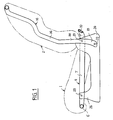
- - la Fig. 1 est une vue en coupe longitudinale d'une armature de siège selon l'invention ;
- - la Fig. 2 est une vue schématique de dessus du cadre de l'assise ;
- - la Fig. 3 est une vue de détail à plus grande échelle, en coupe suivant la ligne 3-3 de la figure 2.
- Le siège représenté sur les figures est destiné à être monté dans un véhicule automobile, ou analogue. Il est constitué, de la manière habituelle, par une assise 1 et un dossier 2 articulés entre eux et formés chacun par une armature métallique supportant une nappe élastique et recouverte d'un rembourrage.
- Selon l'invention, l'armature métallique de l'assise 1 est constituée par un cadre réalisé au moyen d'un tube unique 4 recourbé et soudé sur lui même. Ce tube a une section sensiblement circulaire sur l'un des côtés du cadre, le côté avant 6. Par contre, il est ovalisé et comporte deux faces planes, sensiblement parallèles, sur les deux côtés 7 et 8 adjacents au côté avant 6 ainsi que sur le côté arrière 10. Les faces planes des côtés latéraux 7 et 8 sont sensiblement verticales, tandis que celles du côté arrière 10 sont de préférence inclinées. Le côté arrière est conformé, par exemple incurvé,de façon à assurer un dégagement pour les pieds d'un passager arrière.
- A leur jonction avec le côté arrière 10 chacun des côtés latéraux 7 est aplati en 12, de sorte que sa paroi extérieure est presque en contact avec sa paroi interne plate. De préférence, un aplatissement 14 est également prévu dans la face externe des côtés 7 et 8, au voisinage du côté avant 6.
- Le cadre 16 du dossier 2 est également réalisé au moyen d'un tube unique. Ce tube a une section sensiblement circulaire et est recourbé en U renversé, les extrémités de ses deux branches étant aplaties de façon à constituer des pattes de fixation 18. Chacune des pattes de fixation 18 est introduite à l'intérieur du cadre 4 de l'assise et assemblée à ce cadre au moyen d'un axe d'articulation 20 traversant la portion aplatie 12 du cadre.
- Les pattes de fixation 18 se prolongent vers le bas au-delà de l'axe d'articulation 20, de façon à permettre l'assemblage du cadre 16 sur un support, cet assemblage pouvant être obtenu au moyen d'un organe de fixation, par exemple une vis 22 dont la position est choisie en fonction de l'inclinaison désirée pour le cadre 16 et, par suite, pour le dossier 2.
- L'ensemble du dossier et de l'assise, c'est-à-dire en fait des cadres 4 et 16, est de préférence monté sur un flasque 24 qui se prolonge entre le cadre 4 et la patte de fixation correspondante 18 et est, comme ces derniers organes, traversé par l'axe d'articulation 20.
- Le flasque 24, dans le mode de réalisation représenté, comporte une aile 26 en saillie vers le haut, qui est également fixée au cadre 4 au moyen d'une vis, ou analogue, 28 traversant la partie aplatie 14 du côté latéral 7 ou 8. Cette fixation de l'assise 4, aux deux points 20 et 28, sur le flasque 24 permet un guidage précis de l'ensemble et une rigidification de la structure.
- Le flasque 24 peut être un orgàne immobilisé par rapport au châssis du véhicule, de sorte que l'ensemble du siège est immobile, ou il peut être constitué - comme représenté sur la figure 3 - par le prolongement d'un coulisseau 30 susceptible de se déplacer dans une glissière 32 fixée sur le plancher du véhicule. Dans ce cas, l'ensemble du siège est réglable en translation par rapport à la glissière 32.
- De même au lieu d'être fixes, les pattes de fixation 18 peuvent être reliées à un dispositif de réglage de l'inclinaison du dossier qui commande leur pivotement autour de l'axe 20 jusqu'à la position recherchée. Ces pattes peuvent, également, être libres et simplement associées à un organe escamotable de retenue lorsque le dossier 2 doit pouvoir être rabattu sur l'assise 1.
- La présence de cet organe de retenue,de même que celle du dispositif de réglage d'inclinaison,ne modifie en rien la structure du siège de sorte qu'ils peuvent être ajoutés ou non, à volonté.
- De préférence, les branches du cadre 16 du dossier sont recourbées pour former un bossage 36 en saillie en direction de l'assise, au-dessus d'une branche 38 sensiblement verticale, qui est prolongée par la patte de fixation 18, ce qui permet par exemple une meilleure habitabilité pour les genoux d'un passager arrière.
- Dans tous les cas le cadre d'assise présente une résistance importante grâce notamment àl'aplatissement de ses côtés latéraux et à leur fixation sur le flasque 24 tandis que sa réalisation, de même que celle du cadre du dossier, est simple et peu coûteuse et peut aisément être effectuée pratiquement sans soudure. On dispose donc d'un siège qui peut être utilisé aussi bien sur des véhicules bon marché que sur des véhicules luxueux utilisant des systèmes de réglage à commande électrique. Le prix de revient et la résistance de l'armature peuvent d'ailleurs être encore réduits en perçant les trous de passage de l'axe d'articulation et/ou de fixation du flasque 24 sur le cadre par un procédé de fluoperçage qui permet de réaliser en même temps que le trou un manchon 40 jouant le rôle de palier.
Claims (8)
Priority Applications (1)
| Application Number | Priority Date | Filing Date | Title |
|---|---|---|---|
| AT87400006T ATE43814T1 (de) | 1986-01-27 | 1987-01-05 | Sitzarmatur eines kraftwagens. |
Applications Claiming Priority (2)
| Application Number | Priority Date | Filing Date | Title |
|---|---|---|---|
| FR8601091 | 1986-01-27 | ||
| FR8601091A FR2593440B1 (fr) | 1986-01-27 | 1986-01-27 | Armature de siege de vehicule automobile ou analogue |
Publications (2)
| Publication Number | Publication Date |
|---|---|
| EP0236146A1 true EP0236146A1 (fr) | 1987-09-09 |
| EP0236146B1 EP0236146B1 (fr) | 1989-06-07 |
Family
ID=9331502
Family Applications (1)
| Application Number | Title | Priority Date | Filing Date |
|---|---|---|---|
| EP87400006A Expired EP0236146B1 (fr) | 1986-01-27 | 1987-01-05 | Armature de siège de véhicule automobile ou analogue |
Country Status (9)
| Country | Link |
|---|---|
| EP (1) | EP0236146B1 (fr) |
| JP (1) | JPH0757207B2 (fr) |
| KR (1) | KR870007013A (fr) |
| AT (1) | ATE43814T1 (fr) |
| CA (1) | CA1269607A (fr) |
| DE (1) | DE3760219D1 (fr) |
| ES (1) | ES2008867B3 (fr) |
| FR (1) | FR2593440B1 (fr) |
| MX (1) | MX159900A (fr) |
Cited By (6)
| Publication number | Priority date | Publication date | Assignee | Title |
|---|---|---|---|---|
| FR2631291A1 (fr) * | 1988-05-11 | 1989-11-17 | Honda Motor Co Ltd | |
| WO1993016896A1 (fr) * | 1992-02-24 | 1993-09-02 | Itt Industries, Inc. | Structure de siege tres resistant pour vehicule automobile et procede de fabrication |
| US5412860A (en) * | 1990-11-26 | 1995-05-09 | Ikeda Bussan Co., Ltd. | Method of making a back-rest frame for a seat |
| US5570508A (en) * | 1993-12-03 | 1996-11-05 | Itt Industries, Inc. | Method of making a high strength automotive seat frame |
| EP1031461A3 (fr) * | 1999-02-23 | 2001-01-31 | EvoBus GmbH | Dossier pour sièges de véhicules |
| FR3078925A1 (fr) * | 2018-03-19 | 2019-09-20 | Faurecia Sieges D'automobile | Siege pour vehicule automobile |
Families Citing this family (3)
| Publication number | Priority date | Publication date | Assignee | Title |
|---|---|---|---|---|
| EP0356004A3 (fr) * | 1988-08-19 | 1991-05-15 | Hoover Universal, Inc. | Ensemble de siège d'automobile et procédé d'installation de celui-ci |
| JPH04114827U (ja) * | 1991-03-27 | 1992-10-09 | つばさ観光バス株式会社 | バスの座席 |
| JP4962693B2 (ja) * | 2005-12-07 | 2012-06-27 | マツダ株式会社 | 車両のシート配設構造 |
Citations (5)
| Publication number | Priority date | Publication date | Assignee | Title |
|---|---|---|---|---|
| FR2294667A1 (fr) * | 1974-12-19 | 1976-07-16 | Bremshey Ag | Siege |
| FR2328365A7 (fr) * | 1973-02-17 | 1977-05-13 | Hammerstein Gmbh C Rob | Dispositif reglable pour sieges de vehicules |
| FR2373255A1 (fr) * | 1976-12-10 | 1978-07-07 | Farelli Mario | Siege coulissant et inclinable, destine a des vehicules automobiles |
| FR2411104A1 (fr) * | 1977-12-12 | 1979-07-06 | Renault | Armature pliante pour siege escamotable de vehicule |
| US4492408A (en) * | 1982-01-19 | 1985-01-08 | Allen Industries, Inc. | Vehicle seat construction and method of making the same |
Family Cites Families (4)
| Publication number | Priority date | Publication date | Assignee | Title |
|---|---|---|---|---|
| JPS58112161U (ja) * | 1982-01-26 | 1983-07-30 | 日本発条株式会社 | シ−トクツシヨンフレ−ム構造 |
| JPS59136337U (ja) * | 1983-03-03 | 1984-09-11 | 日産車体株式会社 | 衝撃吸収式シ−トバツクフレ−ム |
| JPS59141849U (ja) * | 1983-03-11 | 1984-09-21 | 難波プレス工業株式会社 | 自動車座席等の背面クツシヨン体 |
| JPS59184234U (ja) * | 1983-05-26 | 1984-12-07 | 三菱自動車工業株式会社 | シ−トフレ−ム |
-
1986
- 1986-01-27 FR FR8601091A patent/FR2593440B1/fr not_active Expired
-
1987
- 1987-01-05 ES ES87400006T patent/ES2008867B3/es not_active Expired
- 1987-01-05 EP EP87400006A patent/EP0236146B1/fr not_active Expired
- 1987-01-05 AT AT87400006T patent/ATE43814T1/de not_active IP Right Cessation
- 1987-01-05 DE DE8787400006T patent/DE3760219D1/de not_active Expired
- 1987-01-06 KR KR870000035A patent/KR870007013A/ko not_active Withdrawn
- 1987-01-22 CA CA000527882A patent/CA1269607A/fr not_active Expired - Fee Related
- 1987-01-26 MX MX5036A patent/MX159900A/es unknown
- 1987-01-26 JP JP62014329A patent/JPH0757207B2/ja not_active Expired - Lifetime
Patent Citations (5)
| Publication number | Priority date | Publication date | Assignee | Title |
|---|---|---|---|---|
| FR2328365A7 (fr) * | 1973-02-17 | 1977-05-13 | Hammerstein Gmbh C Rob | Dispositif reglable pour sieges de vehicules |
| FR2294667A1 (fr) * | 1974-12-19 | 1976-07-16 | Bremshey Ag | Siege |
| FR2373255A1 (fr) * | 1976-12-10 | 1978-07-07 | Farelli Mario | Siege coulissant et inclinable, destine a des vehicules automobiles |
| FR2411104A1 (fr) * | 1977-12-12 | 1979-07-06 | Renault | Armature pliante pour siege escamotable de vehicule |
| US4492408A (en) * | 1982-01-19 | 1985-01-08 | Allen Industries, Inc. | Vehicle seat construction and method of making the same |
Cited By (7)
| Publication number | Priority date | Publication date | Assignee | Title |
|---|---|---|---|---|
| FR2631291A1 (fr) * | 1988-05-11 | 1989-11-17 | Honda Motor Co Ltd | |
| US5412860A (en) * | 1990-11-26 | 1995-05-09 | Ikeda Bussan Co., Ltd. | Method of making a back-rest frame for a seat |
| WO1993016896A1 (fr) * | 1992-02-24 | 1993-09-02 | Itt Industries, Inc. | Structure de siege tres resistant pour vehicule automobile et procede de fabrication |
| US5338100A (en) * | 1992-02-24 | 1994-08-16 | Itt Corporation | High strength automotive seat frame and method |
| US5570508A (en) * | 1993-12-03 | 1996-11-05 | Itt Industries, Inc. | Method of making a high strength automotive seat frame |
| EP1031461A3 (fr) * | 1999-02-23 | 2001-01-31 | EvoBus GmbH | Dossier pour sièges de véhicules |
| FR3078925A1 (fr) * | 2018-03-19 | 2019-09-20 | Faurecia Sieges D'automobile | Siege pour vehicule automobile |
Also Published As
| Publication number | Publication date |
|---|---|
| JPS62192117A (ja) | 1987-08-22 |
| ATE43814T1 (de) | 1989-06-15 |
| FR2593440A1 (fr) | 1987-07-31 |
| JPH0757207B2 (ja) | 1995-06-21 |
| FR2593440B1 (fr) | 1988-05-06 |
| DE3760219D1 (en) | 1989-07-13 |
| KR870007013A (ko) | 1987-08-14 |
| EP0236146B1 (fr) | 1989-06-07 |
| MX159900A (es) | 1989-09-29 |
| CA1269607A (fr) | 1990-05-29 |
| ES2008867B3 (es) | 1989-08-16 |
Similar Documents
| Publication | Publication Date | Title |
|---|---|---|
| EP0236146B1 (fr) | Armature de siège de véhicule automobile ou analogue | |
| FR2548705A1 (fr) | Accessoire prolongateur pour dispositif de signalisation au sol | |
| EP0401086A1 (fr) | Siège pour enfant de largeur réglable | |
| FR2845893A1 (fr) | Fauteuil roulant comportant un dossier inclinable | |
| FR2851206A1 (fr) | Structure de siege pivotant comportant une unite de verrouillage, notamment pour vehicule automobile | |
| FR2730960A1 (fr) | Dispositif d'inclinaison de dossier de siege, notamment de vehicule | |
| EP0050999B1 (fr) | Colonne de direction réglable en hauteur | |
| FR2921022A1 (fr) | Mecanisme de reglage a vis, glissiere comportant un tel mecanisme de reglage et siege comportant une telle glissiere | |
| EP0895895B1 (fr) | Siège pour véhicule automobile | |
| FR2822037A1 (fr) | Dispositif d'assise comportant au moins un element de siege pivotant | |
| FR2480686A1 (fr) | Toit ouvrant de vehicule automobile avec deflecteur contre le vent | |
| EP3381753B1 (fr) | Brin-boucle basculant | |
| FR2554066A1 (fr) | Systeme de construction de retroviseurs de vehicules | |
| FR2783758A1 (fr) | Dispositif formant renfort de porte pour vehicule automobile | |
| FR2660376A1 (fr) | Patte de support. | |
| FR2730460A1 (fr) | Dispositif de reglage de l'ecartement des accoudoirs de siege pour enfants | |
| FR2810280A1 (fr) | Dispositif amortisseur de chocs pour un dossier de siege, notamment de vehicule automobile | |
| EP1302366B1 (fr) | Habitacle de véhicule automobile avec dispositif d'aménagement d'un volume de rangement | |
| FR2630378A1 (fr) | Siege a dossier reglable et rabattable | |
| FR2773760A1 (fr) | Poussette pour enfant, a hamac allongeable telescopique, et hamac correspondant | |
| FR2491402A1 (fr) | Pare-soleil, notamment pour vehicule automobile | |
| FR2737691A1 (fr) | Retroviseur exterieur de vehicules automobiles | |
| FR2778876A1 (fr) | Dispositif de verrouillage d'un dossier inclinable d'une banquette dans un vehicule | |
| EP0572345B1 (fr) | Accoudoir pour sièges avant de véhicule | |
| FR2761313A1 (fr) | Console de pavillon de vehicule automobile adaptee pour etre montee sur la garniture de pavillon de vehicule et procede de montage de la console sur la garniture |
Legal Events
| Date | Code | Title | Description |
|---|---|---|---|
| PUAI | Public reference made under article 153(3) epc to a published international application that has entered the european phase |
Free format text: ORIGINAL CODE: 0009012 |
|
| AK | Designated contracting states |
Kind code of ref document: A1 Designated state(s): AT BE CH DE ES GB IT LI LU NL SE |
|
| 17P | Request for examination filed |
Effective date: 19870727 |
|
| 17Q | First examination report despatched |
Effective date: 19880316 |
|
| RAP1 | Party data changed (applicant data changed or rights of an application transferred) |
Owner name: ECIA - EQUIPEMENTS ET COMPOSANTS POUR L'INDUSTRIE |
|
| GRAA | (expected) grant |
Free format text: ORIGINAL CODE: 0009210 |
|
| AK | Designated contracting states |
Kind code of ref document: B1 Designated state(s): AT BE CH DE ES GB IT LI LU NL SE |
|
| REF | Corresponds to: |
Ref document number: 43814 Country of ref document: AT Date of ref document: 19890615 Kind code of ref document: T |
|
| ITF | It: translation for a ep patent filed | ||
| GBT | Gb: translation of ep patent filed (gb section 77(6)(a)/1977) | ||
| REF | Corresponds to: |
Ref document number: 3760219 Country of ref document: DE Date of ref document: 19890713 |
|
| PLBE | No opposition filed within time limit |
Free format text: ORIGINAL CODE: 0009261 |
|
| STAA | Information on the status of an ep patent application or granted ep patent |
Free format text: STATUS: NO OPPOSITION FILED WITHIN TIME LIMIT |
|
| 26N | No opposition filed | ||
| PGFP | Annual fee paid to national office [announced via postgrant information from national office to epo] |
Ref country code: AT Payment date: 19901227 Year of fee payment: 5 |
|
| PGFP | Annual fee paid to national office [announced via postgrant information from national office to epo] |
Ref country code: LU Payment date: 19910108 Year of fee payment: 5 |
|
| PGFP | Annual fee paid to national office [announced via postgrant information from national office to epo] |
Ref country code: CH Payment date: 19910110 Year of fee payment: 5 |
|
| PGFP | Annual fee paid to national office [announced via postgrant information from national office to epo] |
Ref country code: BE Payment date: 19910214 Year of fee payment: 5 |
|
| EPTA | Lu: last paid annual fee | ||
| PG25 | Lapsed in a contracting state [announced via postgrant information from national office to epo] |
Ref country code: LU Free format text: LAPSE BECAUSE OF NON-PAYMENT OF DUE FEES Effective date: 19920105 Ref country code: AT Effective date: 19920105 |
|
| ITTA | It: last paid annual fee | ||
| PG25 | Lapsed in a contracting state [announced via postgrant information from national office to epo] |
Ref country code: LI Effective date: 19920131 Ref country code: CH Effective date: 19920131 Ref country code: BE Effective date: 19920131 |
|
| BERE | Be: lapsed |
Owner name: EQUIPEMENTS ET COMPOSANTS POUR L'INDUSTRIE AUTOMOB Effective date: 19920131 |
|
| REG | Reference to a national code |
Ref country code: CH Ref legal event code: PL |
|
| REG | Reference to a national code |
Ref country code: GB Ref legal event code: 732 |
|
| ITPR | It: changes in ownership of a european patent |
Owner name: CESSIONE;CESA - COMPAGNIE EUROPEENNE DE SIEGES POU |
|
| REG | Reference to a national code |
Ref country code: ES Ref legal event code: PC2A Owner name: CESA-COMPAGNIE EUROPEENNE DE SIEGES POUR AUTOMOBIL |
|
| NLS | Nl: assignments of ep-patents |
Owner name: CESA-COMPAGNIE EUROPEENNE DE SIEGES POUR AUTOMOBIL |
|
| EAL | Se: european patent in force in sweden |
Ref document number: 87400006.0 |
|
| PGFP | Annual fee paid to national office [announced via postgrant information from national office to epo] |
Ref country code: NL Payment date: 19961223 Year of fee payment: 11 |
|
| PGFP | Annual fee paid to national office [announced via postgrant information from national office to epo] |
Ref country code: DE Payment date: 19961227 Year of fee payment: 11 |
|
| PGFP | Annual fee paid to national office [announced via postgrant information from national office to epo] |
Ref country code: GB Payment date: 19961231 Year of fee payment: 11 |
|
| PGFP | Annual fee paid to national office [announced via postgrant information from national office to epo] |
Ref country code: ES Payment date: 19970113 Year of fee payment: 11 |
|
| PGFP | Annual fee paid to national office [announced via postgrant information from national office to epo] |
Ref country code: SE Payment date: 19970123 Year of fee payment: 11 |
|
| PG25 | Lapsed in a contracting state [announced via postgrant information from national office to epo] |
Ref country code: GB Free format text: LAPSE BECAUSE OF NON-PAYMENT OF DUE FEES Effective date: 19980105 |
|
| PG25 | Lapsed in a contracting state [announced via postgrant information from national office to epo] |
Ref country code: SE Free format text: LAPSE BECAUSE OF NON-PAYMENT OF DUE FEES Effective date: 19980106 |
|
| PG25 | Lapsed in a contracting state [announced via postgrant information from national office to epo] |
Ref country code: ES Free format text: LAPSE BECAUSE OF NON-PAYMENT OF DUE FEES Effective date: 19980107 |
|
| PG25 | Lapsed in a contracting state [announced via postgrant information from national office to epo] |
Ref country code: NL Free format text: LAPSE BECAUSE OF NON-PAYMENT OF DUE FEES Effective date: 19980801 |
|
| GBPC | Gb: european patent ceased through non-payment of renewal fee |
Effective date: 19980105 |
|
| NLV4 | Nl: lapsed or anulled due to non-payment of the annual fee |
Effective date: 19980801 |
|
| EUG | Se: european patent has lapsed |
Ref document number: 87400006.0 |
|
| PG25 | Lapsed in a contracting state [announced via postgrant information from national office to epo] |
Ref country code: DE Free format text: LAPSE BECAUSE OF NON-PAYMENT OF DUE FEES Effective date: 19981103 |
|
| REG | Reference to a national code |
Ref country code: ES Ref legal event code: FD2A Effective date: 20000403 |
|
| PG25 | Lapsed in a contracting state [announced via postgrant information from national office to epo] |
Ref country code: IT Free format text: LAPSE BECAUSE OF NON-PAYMENT OF DUE FEES Effective date: 20050105 |