EP0236205A1 - Konsistenzmessvorrichtung zur Bestimmung der Evolution der rheologischen Eigenschaften, insbesondere zum Gebrauch auf der Arbeitsstelle - Google Patents
Konsistenzmessvorrichtung zur Bestimmung der Evolution der rheologischen Eigenschaften, insbesondere zum Gebrauch auf der Arbeitsstelle Download PDFInfo
- Publication number
- EP0236205A1 EP0236205A1 EP87400338A EP87400338A EP0236205A1 EP 0236205 A1 EP0236205 A1 EP 0236205A1 EP 87400338 A EP87400338 A EP 87400338A EP 87400338 A EP87400338 A EP 87400338A EP 0236205 A1 EP0236205 A1 EP 0236205A1
- Authority
- EP
- European Patent Office
- Prior art keywords
- container
- rod
- consistometer
- enclosure
- coupling device
- Prior art date
- Legal status (The legal status is an assumption and is not a legal conclusion. Google has not performed a legal analysis and makes no representation as to the accuracy of the status listed.)
- Granted
Links
Images


Classifications
-
- G—PHYSICS
- G01—MEASURING; TESTING
- G01N—INVESTIGATING OR ANALYSING MATERIALS BY DETERMINING THEIR CHEMICAL OR PHYSICAL PROPERTIES
- G01N11/00—Investigating flow properties of materials, e.g. viscosity, plasticity; Analysing materials by determining flow properties
- G01N11/10—Investigating flow properties of materials, e.g. viscosity, plasticity; Analysing materials by determining flow properties by moving a body within the material
- G01N11/14—Investigating flow properties of materials, e.g. viscosity, plasticity; Analysing materials by determining flow properties by moving a body within the material by using rotary bodies, e.g. vane
Definitions
- the present invention relates to consistometers comprising an enclosure in which a container receiving a rheologically evolving material such as for example a cement slag is installed and which is capable of receiving a pressurized fluid whose pressure is transmitted to this material by a closing membrane said container, while measuring equipment allows the study of the rheological evolution of this material.
- a rheologically evolving material such as for example a cement slag
- An objective of the present invention is to simplify the production of these consistometers to make them universal use while retaining good measurement accuracy. Another objective is to reduce the duration and, consequently, the cost of the manipulations preceding and following the measurement period proper.
- the invention provides a consistometer comprising an envelope of generally cylindrical shape, forming a consistometer enclosure, arranged vertically and open at its upper part, an upper plug adapted to be screwed onto this upper part to close it, means of introduction of a pressurized fluid into said enclosure, an elongated container in the form of a body of revolution about an axis, provided with closure means at its two ends, partially delimited by an elastic membrane, and suitable for being installed vertically in said enclosure and to receive a rheologically evolving material, a paddle agitator intended to be placed in said container and provided with a drive rod, a shaft bearing in said means for closing the lower longitudinal end of said container for the tight passage of said rod, a motor equipment placed outside of said casing and provided for driving said rod in rotation and means for measuring the driving torque of this rod, characterized in that said casing comprises in its lower part, an appendage in which is disposed vertically an intermediate motion transmission shaft of rotation which is provided with a torque receiving member cooperating in a torque transmission system of the
- the magnetic type torque transmission system preferably comprises a permanent magnet for driving integral with rotation of said motor equipment, installed outside the appendix and a permanent magnet for driving integral with rotation for said intermediate shaft, installed for inside the appendix.
- a spring tending to separate said coupling device vertically from said intermediate shaft is advantageously inserted between this coupling device and this intermediate shaft to compensate for variations in length of said rod, mechanical means of mutual engagement ensuring moreover, the connection in rotation of the coupling device and of the intermediate shaft.
- Said coupling device may in particular comprise a vertical housing capable of receiving said rod and provided laterally with a lug resiliently biased towards the interior of this housing, while said rod has at its lower end a vertical groove in which said ergot can engage.
- a significant simplification can also be obtained by providing that the means for closing the upper longitudinal end of said container is constituted by said upper cap, the container possibly having an outer ring which can be tightened against said upper cap by means of '' a clamping ring screwed inside on this plug.
- Said shaft bearing is advantageously rigidly carried by a lower plug capable of being screwed to the lower longitudinal end of said container, which makes it possible to fill the container, by removing this lower plug and by fixing the container to the upper plug, the upper container-cap assembly being inverted relative to the position to be taken next in the consistometer.
- the upper end of said rod can be held by a pivot formed in said upper plug.
- the elastic membrane must not compromise the rigidity of said container and it must in particular be separated from the support points of said rod.
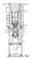
- the consistometer shown in FIG. 1 comprises a frame 1 which supports an envelope 2 made of a non-magnetic material such as for example aluminum or an aluminum alloy, internally delimiting a consistometer enclosure 3 and which houses a speed reducer motor 4 driving by the 'via a torque meter 5 a motor shaft 6.
- a frame 1 which supports an envelope 2 made of a non-magnetic material such as for example aluminum or an aluminum alloy, internally delimiting a consistometer enclosure 3 and which houses a speed reducer motor 4 driving by the 'via a torque meter 5 a motor shaft 6.
- the enclosure 3 is closed at the upper part by an upper plug 7 which can be screwed into the casing 2 by means of removable handles 8.
- This upper cap carries the container with rheologically evolving material 9, made of aluminum alloy, which can be seen better in FIGS. 2 and 3.
- This container 9 has the shape of a cylinder, for example with an internal diameter of 60 mm, the side wall of which is provided with lights 10, the upper longitudinal end of which carries an outer ring 11 and the l 'lower longitudinal end is closed by a lower plug 12.
- This plug 12 can be screwed inside the side wall of the container 9, in a reinforced portion thereof.
- This plug 12 carries in its center a rotating shaft seal 13, for example a PAULSTRA seal type IE. Proper centering of the plug 12 and, consequently, of the shaft seal 13 is obtained by a bearing 14 provided at the end of the thread of the plug, which engages in a corresponding recess in the wall of the container 9.
- the container 9 is fixed to the upper plug 7 by tightening the ferrule 11 against this container by means of a quick-screw ring 16, as seen in FIG. 1.
- the container 9 contains an agitator 17 carried by a drive rod 18 which passes through the shaft seal 13 and extends downwards out of the container 9 and which is supported at its upper end on a pivot 19 formed in the upper plug 7.
- the casing 2 is extended downwards by a central appendage 20. Externally to this appendage 20 and around it, is disposed a permanent drive magnet 21 linked in rotation to the motor shaft 6. Inside of the appendix 20, and opposite the drive magnet 21 is disposed a permanent magnet driven 22 integral in rotation with an intermediate transmission shaft 23 carrying a coupling device 24.
- the appendix 20 serves bearing support for these two magnets 21 and 22.
- the coupling device 24 comprises a housing 25 designed to receive the lower end of the rod 18.
- the latter is laterally provided with a vertical groove 26 into which a lug 27 carried by the coupling device 24 can penetrate and pushed by a spring towards the interior of the housing 25.
- the lug 27 enters the groove 26.
- a vertical play take-up is provided to maintain the upper end of the rod 18 in the pivot 19.
- the coupling device 24 is linked in rotation to the intermediate shaft 23 but it can move vertically , a spring 28 providing compensation for variations in length of the rod 18.
- the introduction of a pressurized fluid into the enclosure 3 and the removal thereof is carried out by means of conduits 29 and 30.
- the heating is carried out by means of a heating cord 31 embedded outside of the envelope 2. It is possible to reach a pressure of 1000 bars and a temperature of 200 ° C.
- the agitator 17 is placed in the container 9 and the assembly is fixed to the upper plug 7 by screwing the ring 16 by means of a special key.
- the membrane 15 is fitted onto the container 9, taking care to leave a similar bearing on each side of the openings 10, and the container 9 is filled, for example with slag cement.
- the container 9 and the rod 18 are placed in the working position, the lower end of which engages in the coupling device 24.
- the agitator 17 is driven at constant speed, for example at 150 rpm.
- the temperature and pressure can be changed according to a program; in the case of a cement slag for a wellbore, this program is established in accordance with API standards.
- the variation in the drive torque measured by the torque meter 5 is recorded as a function of time in order to determine the setting time of the slag.
- the intensity of the motor 4 could also be measured, but the measurement of the consistency of the slag thus carried out would be less precise.
Landscapes
- Immunology (AREA)
- Pathology (AREA)
- Life Sciences & Earth Sciences (AREA)
- Chemical & Material Sciences (AREA)
- Analytical Chemistry (AREA)
- Biochemistry (AREA)
- General Health & Medical Sciences (AREA)
- General Physics & Mathematics (AREA)
- Health & Medical Sciences (AREA)
- Physics & Mathematics (AREA)
- Sampling And Sample Adjustment (AREA)
- Investigating Strength Of Materials By Application Of Mechanical Stress (AREA)
- Investigating Or Analyzing Materials Using Thermal Means (AREA)
- Mixers Of The Rotary Stirring Type (AREA)
- Pressure Vessels And Lids Thereof (AREA)
- Analysing Materials By The Use Of Radiation (AREA)
- Measuring Or Testing Involving Enzymes Or Micro-Organisms (AREA)
- Curing Cements, Concrete, And Artificial Stone (AREA)
Applications Claiming Priority (2)
| Application Number | Priority Date | Filing Date | Title |
|---|---|---|---|
| FR8602701A FR2594950B1 (fr) | 1986-02-27 | 1986-02-27 | Consistometre d'analyse d'evolution rheologique, notamment utilisable sur un chantier |
| FR8602701 | 1986-02-27 |
Publications (2)
| Publication Number | Publication Date |
|---|---|
| EP0236205A1 true EP0236205A1 (de) | 1987-09-09 |
| EP0236205B1 EP0236205B1 (de) | 1991-01-23 |
Family
ID=9332575
Family Applications (1)
| Application Number | Title | Priority Date | Filing Date |
|---|---|---|---|
| EP87400338A Expired - Lifetime EP0236205B1 (de) | 1986-02-27 | 1987-02-17 | Konsistenzmessvorrichtung zur Bestimmung der Evolution der rheologischen Eigenschaften, insbesondere zum Gebrauch auf der Arbeitsstelle |
Country Status (14)
| Country | Link |
|---|---|
| US (1) | US4736624A (de) |
| EP (1) | EP0236205B1 (de) |
| JP (1) | JP2518638B2 (de) |
| AU (1) | AU587310B2 (de) |
| BR (1) | BR8700899A (de) |
| CA (1) | CA1274988A (de) |
| DE (1) | DE3767509D1 (de) |
| DK (1) | DK166844B1 (de) |
| FI (1) | FI90468C (de) |
| FR (1) | FR2594950B1 (de) |
| GB (1) | GB2187295B (de) |
| IE (1) | IE59838B1 (de) |
| MX (1) | MX169137B (de) |
| NO (1) | NO169362C (de) |
Cited By (3)
| Publication number | Priority date | Publication date | Assignee | Title |
|---|---|---|---|---|
| WO1990010213A1 (de) * | 1989-02-24 | 1990-09-07 | Contraves Gmbh | Vorrichtung zum bestimmen bzw. messen einer substanz |
| FR2678381A1 (fr) * | 1991-06-27 | 1992-12-31 | Total Sa | Consistometre. |
| FR2687223A1 (fr) * | 1992-02-12 | 1993-08-13 | Inst Francais Du Petrole | Dispositif et methode pour surveiller les variations de consistance d'un melange. |
Families Citing this family (12)
| Publication number | Priority date | Publication date | Assignee | Title |
|---|---|---|---|---|
| DE3914868A1 (de) * | 1989-05-05 | 1990-11-08 | Helmut Gerard | Pruefgeraet zur messung des erstarrungszeitpunktes eines gips-wasser-gemisches |
| SE503681C2 (sv) * | 1994-11-21 | 1996-07-29 | Reologica Instr Ab | Reologiskt mätaggregat |
| FR2737780B1 (fr) * | 1995-08-11 | 1997-09-19 | Inst Francais Du Petrole | Cellule d'essai de melanges fluides adaptee a detecter des changements de phases |
| US5652376A (en) * | 1996-07-05 | 1997-07-29 | Dow Corning Corporation | Method of measuring yield stress |
| US6257051B1 (en) | 1999-03-11 | 2001-07-10 | The Lubrizol Corporation | On-board rotational viscometers |
| US6231646B1 (en) | 1999-03-11 | 2001-05-15 | Chemco Manufacturing Company, Inc. | Paint overspray exhaust air filter |
| US7287416B1 (en) | 2005-10-24 | 2007-10-30 | Hongfeng Bi | Low maintenance high pressure viscometer |
| US7412877B1 (en) | 2005-10-24 | 2008-08-19 | Hongfeng Bi | High pressure viscometer with chamber preventing sample contamination |
| US8375771B1 (en) | 2010-05-21 | 2013-02-19 | Hongfeng Bi | Viscometer for testing cement rheology |
| CN101949808B (zh) * | 2010-07-30 | 2012-07-04 | 中海油田服务股份有限公司 | 稠化仪新型水泥浆稠度测量装置 |
| US8347693B2 (en) * | 2010-08-26 | 2013-01-08 | Halliburton Energy Services, Inc. | Apparatus and methods for continuous compatibility testing of subterranean fluids and their compositions under wellbore conditions |
| JP6964656B2 (ja) * | 2016-04-29 | 2021-11-10 | ネオテック バイオサイエンス カンパニー リミテッド | ブラケット、支持システム、トロンボエラストグラフ及びその使用方法 |
Citations (5)
| Publication number | Priority date | Publication date | Assignee | Title |
|---|---|---|---|---|
| US3435666A (en) * | 1966-07-18 | 1969-04-01 | Champion Lab Inc | Viscometer |
| US4175425A (en) * | 1977-04-08 | 1979-11-27 | Brookfield David A | Viscometer |
| EP0094319A1 (de) * | 1982-05-11 | 1983-11-16 | Association Pour La Recherche Et Le Developpement Des Methodes Et Processus Industriels (Armines) | Rotationsrheometer zum Durchführen von Messungen unter hohen Temperatur- und Druckverhältnissen mit Probennahmevorrichtung |
| US4466276A (en) * | 1982-09-28 | 1984-08-21 | Autoclave Engineers, Inc. | Consistometer |
| US4534209A (en) * | 1983-09-15 | 1985-08-13 | Sanders Howard E | Atmospheric consistometer |
Family Cites Families (2)
| Publication number | Priority date | Publication date | Assignee | Title |
|---|---|---|---|---|
| GB2097940A (en) * | 1981-05-05 | 1982-11-10 | Viscometers Uk Ltd | Rotary viscometer |
| FR2569850B1 (fr) * | 1984-08-31 | 1987-09-11 | Petroles Cie Francaise | Recipient pour matiere rheologiquement evolutive, utilisable dans un consistometre d'analyse d'evolution rheologique |
-
1986
- 1986-02-27 FR FR8602701A patent/FR2594950B1/fr not_active Expired
-
1987
- 1987-02-02 GB GB8702220A patent/GB2187295B/en not_active Expired
- 1987-02-11 US US07/013,498 patent/US4736624A/en not_active Expired - Fee Related
- 1987-02-12 CA CA000529594A patent/CA1274988A/fr not_active Expired - Lifetime
- 1987-02-17 DE DE8787400338T patent/DE3767509D1/de not_active Expired - Lifetime
- 1987-02-17 EP EP87400338A patent/EP0236205B1/de not_active Expired - Lifetime
- 1987-02-19 MX MX005284A patent/MX169137B/es unknown
- 1987-02-24 AU AU69188/87A patent/AU587310B2/en not_active Ceased
- 1987-02-25 BR BR8700899A patent/BR8700899A/pt not_active IP Right Cessation
- 1987-02-25 IE IE48387A patent/IE59838B1/en not_active IP Right Cessation
- 1987-02-26 NO NO870799A patent/NO169362C/no unknown
- 1987-02-26 DK DK099087A patent/DK166844B1/da not_active IP Right Cessation
- 1987-02-26 FI FI870836A patent/FI90468C/fi not_active IP Right Cessation
- 1987-02-27 JP JP62045063A patent/JP2518638B2/ja not_active Expired - Lifetime
Patent Citations (5)
| Publication number | Priority date | Publication date | Assignee | Title |
|---|---|---|---|---|
| US3435666A (en) * | 1966-07-18 | 1969-04-01 | Champion Lab Inc | Viscometer |
| US4175425A (en) * | 1977-04-08 | 1979-11-27 | Brookfield David A | Viscometer |
| EP0094319A1 (de) * | 1982-05-11 | 1983-11-16 | Association Pour La Recherche Et Le Developpement Des Methodes Et Processus Industriels (Armines) | Rotationsrheometer zum Durchführen von Messungen unter hohen Temperatur- und Druckverhältnissen mit Probennahmevorrichtung |
| US4466276A (en) * | 1982-09-28 | 1984-08-21 | Autoclave Engineers, Inc. | Consistometer |
| US4534209A (en) * | 1983-09-15 | 1985-08-13 | Sanders Howard E | Atmospheric consistometer |
Cited By (3)
| Publication number | Priority date | Publication date | Assignee | Title |
|---|---|---|---|---|
| WO1990010213A1 (de) * | 1989-02-24 | 1990-09-07 | Contraves Gmbh | Vorrichtung zum bestimmen bzw. messen einer substanz |
| FR2678381A1 (fr) * | 1991-06-27 | 1992-12-31 | Total Sa | Consistometre. |
| FR2687223A1 (fr) * | 1992-02-12 | 1993-08-13 | Inst Francais Du Petrole | Dispositif et methode pour surveiller les variations de consistance d'un melange. |
Also Published As
| Publication number | Publication date |
|---|---|
| FI870836L (fi) | 1987-08-28 |
| NO169362B (no) | 1992-03-02 |
| IE59838B1 (en) | 1994-04-06 |
| GB2187295B (en) | 1989-11-29 |
| MX169137B (es) | 1993-06-23 |
| JP2518638B2 (ja) | 1996-07-24 |
| NO870799L (no) | 1987-08-28 |
| GB8702220D0 (en) | 1987-03-11 |
| DE3767509D1 (de) | 1991-02-28 |
| FR2594950B1 (fr) | 1988-05-06 |
| US4736624A (en) | 1988-04-12 |
| AU6918887A (en) | 1987-09-03 |
| AU587310B2 (en) | 1989-08-10 |
| NO870799D0 (no) | 1987-02-26 |
| EP0236205B1 (de) | 1991-01-23 |
| IE870483L (en) | 1987-08-27 |
| FI870836A0 (fi) | 1987-02-26 |
| NO169362C (no) | 1992-06-10 |
| FR2594950A1 (fr) | 1987-08-28 |
| FI90468B (fi) | 1993-10-29 |
| DK99087A (da) | 1987-08-28 |
| FI90468C (fi) | 1994-02-10 |
| GB2187295A (en) | 1987-09-03 |
| DK99087D0 (da) | 1987-02-26 |
| BR8700899A (pt) | 1987-12-15 |
| JPS62204142A (ja) | 1987-09-08 |
| CA1274988A (fr) | 1990-10-09 |
| DK166844B1 (da) | 1993-07-19 |
Similar Documents
| Publication | Publication Date | Title |
|---|---|---|
| CA1274988A (fr) | Consistometre d'analyse d'evolution rheologique, notamment utilisable sur un chantier | |
| EP0094319A1 (de) | Rotationsrheometer zum Durchführen von Messungen unter hohen Temperatur- und Druckverhältnissen mit Probennahmevorrichtung | |
| EP1023936B1 (de) | Rührwerk mit magnetischem Antrieb und Verfahren zur Drehmomenteinstellung für die Kraftübertragung eines derartigen Rührwerks | |
| FR2664982A1 (fr) | Appareil de detection de changement de viscosite, par mesure d'un glissement relatif, en particulier pour la detection du temps de coagulation du sang. | |
| CA1329020C (fr) | Cellule d'essais triaxiaux de contraintes sur un echantillon de roche et methode d'essais utilisant une telle cellule | |
| EP0805652A1 (de) | Vorrichtung zur entnahme von mukosa aus der gebärmutter | |
| EP0032098B1 (de) | Vorrichtung zum Entnehmen und Wiederabgeben wählbarer Flüssigkeitsmengen mit einer numerischen Anzeige | |
| FR2678381A1 (fr) | Consistometre. | |
| FR2503243A1 (fr) | Systeme pour la teletransmission d'informations d'un trou de forage vers la surface du sol | |
| FR2549231A1 (fr) | Mecanisme pour detecter l'ecoulement d'un fluide dans un conduit | |
| EP0176391A1 (de) | Gefäss für ein Instrument zur Überwachung der Entwicklung der rheologischen Eigenschaften | |
| EP2579970B1 (de) | Vorrichtung und verfahren zur messung der eigenschaften eines komplexen mediums durch analyse des unterschieds in rückgestreutem und/oder durchfallendem licht | |
| FR2466000A1 (fr) | Compteur rotatif de fluide | |
| FR2542658A1 (fr) | Manipulateur telescopique | |
| EP0937009B1 (de) | Dichter, flexibler sack zur prüfung von lastaufnahmen | |
| FR3112374A1 (fr) | Motoréducteur à enveloppe cylindrique et moteur tubulaire correspondant. | |
| FR2619434A1 (fr) | Dispositif d'obturation d'une tubulure et procede d'obturation a l'aide de ce dispositif | |
| FR2658104A1 (fr) | Dispositif pour amener un outil sur une paroi. | |
| EP0451072A1 (de) | Durch Fernbedienung lösbarer Schutzgaslichtbogenschweisskopf | |
| FR2711935A1 (fr) | Outil de vissage. | |
| FR2497914A1 (fr) | Dispositif de commande de debit de fluide ainsi que procedes et moyens de montage et de demontage du dispositif | |
| FR2650394A1 (fr) | Perfectionnement aux sondes de detection du taux d'humidite dans un malaxeur | |
| EP0541438A1 (de) | Vorrichtung zum Messen der Temperatur einer Probe | |
| EP0318340A1 (de) | Mischer mit in Schräglage rotierendem Gefäss mit Entleerungsöffnung am Gefässboden | |
| FR2896394A1 (fr) | Mixeur plongeant et procede de demontage facilite |
Legal Events
| Date | Code | Title | Description |
|---|---|---|---|
| PUAI | Public reference made under article 153(3) epc to a published international application that has entered the european phase |
Free format text: ORIGINAL CODE: 0009012 |
|
| AK | Designated contracting states |
Kind code of ref document: A1 Designated state(s): DE IT NL SE |
|
| 17P | Request for examination filed |
Effective date: 19871005 |
|
| 17Q | First examination report despatched |
Effective date: 19890824 |
|
| GRAA | (expected) grant |
Free format text: ORIGINAL CODE: 0009210 |
|
| AK | Designated contracting states |
Kind code of ref document: B1 Designated state(s): DE IT NL SE |
|
| ITF | It: translation for a ep patent filed | ||
| REF | Corresponds to: |
Ref document number: 3767509 Country of ref document: DE Date of ref document: 19910228 |
|
| PLBE | No opposition filed within time limit |
Free format text: ORIGINAL CODE: 0009261 |
|
| STAA | Information on the status of an ep patent application or granted ep patent |
Free format text: STATUS: NO OPPOSITION FILED WITHIN TIME LIMIT |
|
| 26N | No opposition filed | ||
| PGFP | Annual fee paid to national office [announced via postgrant information from national office to epo] |
Ref country code: SE Payment date: 19940125 Year of fee payment: 8 |
|
| EAL | Se: european patent in force in sweden |
Ref document number: 87400338.7 |
|
| PG25 | Lapsed in a contracting state [announced via postgrant information from national office to epo] |
Ref country code: SE Effective date: 19950218 |
|
| EUG | Se: european patent has lapsed |
Ref document number: 87400338.7 |
|
| PGFP | Annual fee paid to national office [announced via postgrant information from national office to epo] |
Ref country code: NL Payment date: 19970227 Year of fee payment: 11 |
|
| PGFP | Annual fee paid to national office [announced via postgrant information from national office to epo] |
Ref country code: DE Payment date: 19980427 Year of fee payment: 12 |
|
| PG25 | Lapsed in a contracting state [announced via postgrant information from national office to epo] |
Ref country code: NL Free format text: LAPSE BECAUSE OF NON-PAYMENT OF DUE FEES Effective date: 19980901 |
|
| NLV4 | Nl: lapsed or anulled due to non-payment of the annual fee |
Effective date: 19980901 |
|
| PG25 | Lapsed in a contracting state [announced via postgrant information from national office to epo] |
Ref country code: DE Free format text: LAPSE BECAUSE OF NON-PAYMENT OF DUE FEES Effective date: 19991201 |
|
| PG25 | Lapsed in a contracting state [announced via postgrant information from national office to epo] |
Ref country code: IT Free format text: LAPSE BECAUSE OF NON-PAYMENT OF DUE FEES;WARNING: LAPSES OF ITALIAN PATENTS WITH EFFECTIVE DATE BEFORE 2007 MAY HAVE OCCURRED AT ANY TIME BEFORE 2007. THE CORRECT EFFECTIVE DATE MAY BE DIFFERENT FROM THE ONE RECORDED. Effective date: 20050217 |