EP0236207A1 - Elektronisches Einspritzverfahren und -system mit Lambdasondenregelung für Brennkraftmaschinen - Google Patents
Elektronisches Einspritzverfahren und -system mit Lambdasondenregelung für Brennkraftmaschinen Download PDFInfo
- Publication number
- EP0236207A1 EP0236207A1 EP87400342A EP87400342A EP0236207A1 EP 0236207 A1 EP0236207 A1 EP 0236207A1 EP 87400342 A EP87400342 A EP 87400342A EP 87400342 A EP87400342 A EP 87400342A EP 0236207 A1 EP0236207 A1 EP 0236207A1
- Authority
- EP
- European Patent Office
- Prior art keywords
- probe
- value
- signal
- probe signal
- simulated
- Prior art date
- Legal status (The legal status is an assumption and is not a legal conclusion. Google has not performed a legal analysis and makes no representation as to the accuracy of the status listed.)
- Granted
Links
Images



Classifications
-
- F—MECHANICAL ENGINEERING; LIGHTING; HEATING; WEAPONS; BLASTING
- F02—COMBUSTION ENGINES; HOT-GAS OR COMBUSTION-PRODUCT ENGINE PLANTS
- F02D—CONTROLLING COMBUSTION ENGINES
- F02D41/00—Electrical control of supply of combustible mixture or its constituents
- F02D41/02—Circuit arrangements for generating control signals
- F02D41/14—Introducing closed-loop corrections
- F02D41/1438—Introducing closed-loop corrections using means for determining characteristics of the combustion gases; Sensors therefor
- F02D41/1477—Introducing closed-loop corrections using means for determining characteristics of the combustion gases; Sensors therefor characterised by the regulation circuit or part of it,(e.g. comparator, PI regulator, output)
- F02D41/1481—Using a delaying circuit
-
- F—MECHANICAL ENGINEERING; LIGHTING; HEATING; WEAPONS; BLASTING
- F02—COMBUSTION ENGINES; HOT-GAS OR COMBUSTION-PRODUCT ENGINE PLANTS
- F02D—CONTROLLING COMBUSTION ENGINES
- F02D41/00—Electrical control of supply of combustible mixture or its constituents
- F02D41/02—Circuit arrangements for generating control signals
- F02D41/14—Introducing closed-loop corrections
- F02D41/1438—Introducing closed-loop corrections using means for determining characteristics of the combustion gases; Sensors therefor
- F02D41/1444—Introducing closed-loop corrections using means for determining characteristics of the combustion gases; Sensors therefor characterised by the characteristics of the combustion gases
- F02D41/1454—Introducing closed-loop corrections using means for determining characteristics of the combustion gases; Sensors therefor characterised by the characteristics of the combustion gases the characteristics being an oxygen content or concentration or the air-fuel ratio
- F02D41/1456—Introducing closed-loop corrections using means for determining characteristics of the combustion gases; Sensors therefor characterised by the characteristics of the combustion gases the characteristics being an oxygen content or concentration or the air-fuel ratio with sensor output signal being linear or quasi-linear with the concentration of oxygen
Definitions
- the invention relates to a method and a system of electronic injection with ⁇ wave regulation for an internal combustion engine, of the type comprising at least one injector whose opening time is controlled by an electronic computer as a function of operating parameters of the engine and probe A status.
- the probe A is a sensor whose output voltage can switch between a high level (rich mixture) and a low level (lean mixture) located on either side of a threshold corresponding to the stoichiometric ratio (richness "1") .
- the output signal of the ⁇ probe is formatted in the electronic injection computer and the resulting logical information is a rectangular signal to which, by convention, the value "+1" is assigned when it is at the level high and steam "-1" when it is low.
- the regulation adapted to this kind of information is the superposition of a proportional type regulation and an integral type regulation.
- Proportional correction makes it possible to increase the frequency of regulation, while integral correction makes it possible more particularly to pass from one operating point to another adapted differently in richness, that is to say to face a mismatch of wealth.
- the invention proposes a method and an injection system with regulation by probe ⁇ which are fundamentally different from traditional solutions while allowing the regulation frequency to be substantially increased.
- the invention can be combined with some of these traditional solutions to further increase the efficiency of regulation.
- the objects of the invention are achieved by means of a method for dosing the fuel supplied to an internal combustion engine by at least one injector controlled by an electronic computer associated with a probe delivering a signal capable of taking one or the other. other of two function states of the composition of the exhaust gases, according to which the electronic computer determines the opening time of the injector from a nominal time function of engine operating parameters and a term of proportional and integral correction as a function of the probe signal, characterized in that a predictive estimate of the richness of the exhaust gases is carried out from engine operating parameters and from the pure delay, experimentally determined, between the injector and the probe , at least one simulated probe signal is developed from said predictive richness estimate, said correction term is developed from the simulated probe signal, and pe is modified periodically said correction term in response to the detection of a difference between the state of the measured probe signal and the state of a delayed simulated probe signal.
- a first simulated probe signal is produced by comparison of the predictive wealth estimate with first high and low thresholds equal respectively to the high and low thresholds for change of state of the probe, the simulated probe signal is obtained. delayed by a time offset of said first signal equal to said pure delay, a second simulated probe signal is produced by comparison of the predictive wealth estimate with second high and low thresholds respectively higher than the first high and low thresholds, and said term is produced correction from the second simulated probe signal.
- a reference term representative of the correction to be made at said nominal time is developed to obtain a state of the probe representative of the richness "1" and a raw estimated value of richness is calculated as a function of the difference between the correction term and the reference term.
- the invention also relates to an electronic injection system for implementing the method defined above, comprising at least one fuel injector on the engine intake side, a probe sensitive to the composition of the exhaust gases, sensors for measuring engine operating parameters and an electronic computer which controls the opening time of the injector as a function of said parameters and of the output signal of said probe, characterized in that said system comprises a digital value read-only memory pure delay addressable by the computer as a function of the air pressure at the engine intake.
- the injector 2 is controlled by a programmed microcomputer 6 via a power circuit 7.
- the microcomputer 6 determines the nominal opening time Tin of the injector 2 as a function of the air pressure measured by a pressure sensor 8 placed on the intake side 3 and of the rotational speed of the notor, This latter information is delivered by a sensor 9 in front of which the teeth of a target 10 pass in rotation with the crankshaft of the engine.
- the target 10 can also be provided with one or more accidents placed in a predetermined angular position to provide angular position information via the sensor 9, or a second target associated with an additional sensor can be provided for this purpose.
- the nominal time Tin can be corrected by the microcomputer 6 as a function of other information such as the temperature of the atmospheric air, the temperature of the engine cooling water, etc. which it possibly receives on auxiliary inputs 11.
- the nominal time Tin is also corrected on the basis of the information delivered by a probe 12 disposed csté exhaust 5, between the engine 1 and the catalyst 4.
- the output signal of the probe ⁇ is shaped in the microcomputer 6 and it then presents the shape of the signal S ⁇ of FIG. 5.
- This signal S ⁇ contains information on the residual oxygen content of the exhaust gases, and also on the momentary ratio of air and fuel of the mixture drawn in by the engine.
- the high and low levels of this signal S ⁇ , to which numerical values "+1" and "-1" are respectively assigned, correspond to riches respectively higher and lower than the stoichiometric ratio (wealth "1"),
- the state of the probe ⁇ is not the instantaneous image of the richness of the mixture admitted into the engine because there is a pure delay between the injector 2 and the probe ⁇ 12.
- This pure delay determined experimentally, is stored in the form of digital values in a read only memory 13 addressable by the computer 6 as a function of the air pressure at the intake of the engine.
- the ROM 13 can be internal or external to the computer 6.
- FIG. 1 relates to a four-cylinder engine comprising a single injector opening for a time Ti at each half-turn of the engine.
- the invention is in no way limited to this specific example and applies to any type of spark-ignition engine, whatever the number of injectors and cylinders which equip it.
- the parameters for calculating the nominal time Tin of opening of the injector 2 are given only by way of examples and it is possible, among other things, to use an air flow sensor instead of the pressure sensor. 8 on the intake side 3. In this case, the memory 13 containing the digital values of pure delay is addressed as a function of the air flow instead of the pressure.
- the gain of the integral correction may be an increasing function of the time elapsed since the last tilting of the probe 12, for example a parabolic function if ⁇ cl is of the following form where G is then a predetermined fixed coefficient involved in determining the gain of the integral correction.
- the invention differs from the solutions recalled above for determining the correction term ⁇ cl by the fact that for this purpose it does not call directly on the measured probe signal S ⁇ , but on a simulated probe signal Ss ⁇ ,
- the method according to the invention is in fact based on the fact that the injection time Ti is adjusted on the basis of an estimate of richness and that the observation of the measured probe signal S ⁇ serves to periodically readjust this estimate. This makes it possible to get rid of the pure delay between the injector and the probe and, therefore, of this step wait for its tilting to effect the proportional correction, which has the consequence of increasing the frequency of richness oscillation.
- the term is representative of the difference in richness with respect to richness 1 at the level of the probe At the instant n + m + 1, m representing the pure delay between the injector and the probe.
- Blocks 13 and 14 represent the values initials of ⁇ cl and ⁇ and in 15 we make the difference ⁇ cl - ⁇ .
- Block 17 represents the entire system of FIG. 1 and includes in particular as a quantity the injection time Ti and the angular position ⁇ m of the engine from which is deduced the number n of engine U-turns that have elapsed since the last tilting of the probe.
- the output variables of block 17 are the measured pressure P and the measured probe signal S A.
- Block 18 represents a low-pass filtering of the pressure P and the difference P - p is performed at 19. This difference is multiplied by the coefficient K 'in 20, the term K' (P - P) being positive in acceleration and negative in deceleration, and making it possible to take into account the problems of wetting of the walls of the intake manifold with the fuel. .
- Block 23 represents the hysteresis of the probe A and reconstructs at the instant n (half-turn n) a simulated probe signal S's ⁇ which is a predictive estimate of what the measured probe signal S ⁇ will be at the time n + m +1.
- block 24 represents the determination of the pure delay m as a function of the air pressure P measured at the intake of the engine.
- Block 25 represents a pure delay m brought to the signal S's ⁇ (n), corresponding to a transfer function e - K "P, and the difference between the simulated probe signal S" s ⁇ is made at 26 (n) and the measured probe signal S ⁇ (n). This difference is multiplied by the coefficient K2 at 27 to be reinjected at 22 as explained above. Furthermore, this same difference S's ⁇ (n) - S ⁇ (n) is multiplied by K1 at 28 to be reinjected at 15.
- the proportional and integral correction on the coefficient ⁇ cl is carried out on the basis of a second simulated probe signal Ss ⁇ (n) produced by block 29 from the non-delayed wealth estimate Re.
- This block 29 has hysteresis larger than the block 23, which allows more frank tilting of the probe 12 since the wealth excursions are amplified.
- the blocks 30 and 31 respectively represent the integral and proportional corrections and the difference obtained at 32 represents the term ⁇ cl which is subtracted at 33 from the initial ⁇ cl. We therefore obtain at the exit from 33 the term ⁇ cl which is injected at 15 with the term ⁇ resulting from the difference made at 34 between the initial ⁇ (block 14) and the calculated ⁇ (block 28).
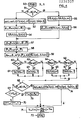
- Figure 4 is a flowchart of operation of the computer 6 which allows to implement the servo diagram of Figure 2.
- Figure 3 is a flowchart of an initialization program which takes place when the engine starts.
- step 40 Upon receipt of an initialization instruction (step 40), the computer 6 loads a predetermined value XX into a CPT counter which counts the engine U-turns (step 41).
- Step 45 represents the end of the initialization program.
- step 50 runs on each detection of the passage of the motor through a position predetermined angular, for example the passage of a piston through the top dead center (step 50).
- step 51 is a test to determine whether or not the engine is still in its starting phase. If this is the case, the counter CPT has not yet been counted down and the flag set in step 42 of the initialization program is always 0.
- step 53 the reference term ⁇ is calculated: where x is a coefficient of predetermined fixed value.
- step 54 which follows consists in giving the simulated probe signal S "s ⁇ (n) the value presented by the measured probe signal S ⁇ (n) at the nth half-turn.
- step 55 the delayed simulated probe signal S''s ⁇ (n) is then given the value presented by the simulated non-delayed probe signal S's ⁇ (nm) ------ m earlier U-turns .
- FIG. 5 it can be seen that the signal S's ⁇ is offset with respect to the signal S's ⁇ of the pure delay m as a function of the pressure P.
- the reference term is then calculated in step 56
- Steps 54 and 56 both lead to step 57 of calculating the term ⁇ where k is a coefficient of predetermined fixed value.
- the next step 59 is the calculation of the predictive estimate of non-delayed wealth Re:
- Step 59 is followed by a series of tests to compare the wealth estimate Re with thresholds D + and D- on the one hand and D '+ and D'- on the other hand.
- the thresholds D + and D- are symmetrical with respect to richness 1, as are the thresholds D '+ and D'- which are higher than the thresholds D + and D- respectively.
- the thresholds D + and D '+ have been shown in FIG. 5, which corresponds to operation in rich mixing, but it is possible to immediately deduce therefrom the various signals which would be obtained in the event of operation in mixing poor by comparison of the estimated wealth Re with the thresholds D- and D'-.
- the first test 60 which follows step 59 consists in comparing Re to the threshold D +. If Re is greater than or equal to D +, the value Ss ⁇ (n) is set to +1 (step 61). Otherwise, we go to test 62 where we compare Re to the threshold D-. If Re is less than or equal to D-, the value Ss ⁇ (n) is set to the value -1 (step 63). Steps 61 and 63 or a negative response to test 62 lead to test 64 where Re is compared to the threshold D '+. If the response to this test is positive, the value S's ⁇ (n) is set to the value +1 (step 65), while in the opposite case we go to test 66 where we compare Re to the threshold D'- .
- Step 67 the value S'sA (n) is set to the value -1 (step 67). Steps 65 and 67, as well as a negative response to test 66, lead to test 68. In the case of a negative response to tests 60 and 62, Ss ⁇ (n) retains the value it had at instant n-1 and, similarly, in the case of a negative response to tests 64 and 66, S's A (n) retains the value it had at instant n-1.
- Test 68 relates to the value of the flag. If the engine is still starting, the flag always has the value 0 fixed in step 42 of the initialization program and the response to test 68 is negative and leads to a test 69 concerning the content of the counter CPT initialized to the value XX in step 41 of the initialization program. In the start-up phase, the content of the CPT counter has still not been brought to 0 and the negative response to the test 69 leads to step 70 where the counter CPT is decremented by one.
- the next step 71 consists in calculating the injection time using the correction term ⁇ cl calculated in step 52:
- the next step 72 marks the end of the program which remains pending the next interruption due to the passage of the engine through a predetermined angular position.
- step 73 When the engine has made XX U-turns, the content of the CPT counter has been counted down to 0 and the response to test 69 is positive. The flag is then set to 1 (step 73), after which we go to step 71 for calculating the injection time Ti.
- step 74 the correction term ⁇ cl is calculated depending on the simulated probe signal Ss ⁇ :
- the term ⁇ cl is always calculated from the simulated probe signal Ss ⁇ , although one can envisage a return to a traditional calculation based on the measured probe signal S ⁇ under certain specific conditions. engine operation.
- FIG. 5 clearly shows the pure delay which exists between the injector 2 and the probe 12 t, it is indeed observed that the real richness at the level of the probe Rr, supposed to be initially at a level to facilitate the understanding of the phenomenon described, does not begins to increase as m half-turns after the increase in the richness of the mixture on admission due to the proportional correction introduced by the presence of a jump in the term ⁇ cl at the supposedly initial time ⁇ has appeared.
- the estimate of ri predictive chess Re starts to increase from the half-turn e to the half-turn p where it reaches the threshold D +.
- ⁇ cl of proportional and integral correction is assumed to be calculated in the conventional manner as indicated by the above formula (2). It should however be noted that this term can be calculated just as well by formula (3) ensuring an integral correction of the parabolic type or by any other appropriate formula. Indeed, the invention does not lie in the actual calculation formula of these terms but in the use, for this purpose, of a simulated probe signal based on a prediction of the evolution of the richness of the gases d exhaust at the level of the probe. In other words, the described method and system ensure richness looping from a signal simulated by an internal model and a recalibration of this internal model is carried out periodically from the observation of the state of the ⁇ probe.
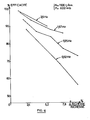
- FIG. 6 represents at different excitation frequencies of the term ⁇ cl the efficiency of a trifunctional catalyst of 54,000 miles as a function of the peak-to-peak amplitude of the richness oscillations at the entry of the catalyst pot. Efficiency is calculated as follows, expressed as a percentage
- FIGS. 7 and 8 relate to an internal combustion engine controlled respectively by a conventional fuel injection method and the method according to the invention.
- These curves represent the spectral analysis of the engine period T expressed in milliseconds at idle speed. It turns out that in the first case. the fundamental line is located around 0.9 Hz, while it is close to 2 Hz with the method of the invention.
- This increase in frequency results not only in a gain in the efficiency of the catalytic converter, but also in a reduction in low-frequency pumping of the engine speed at idle, from which it results an improvement in the vibrational comfort on the vehicle perceptible by a driver .
Landscapes
- Engineering & Computer Science (AREA)
- Chemical & Material Sciences (AREA)
- Combustion & Propulsion (AREA)
- Mechanical Engineering (AREA)
- General Engineering & Computer Science (AREA)
- Electrical Control Of Air Or Fuel Supplied To Internal-Combustion Engine (AREA)
- Combined Controls Of Internal Combustion Engines (AREA)
- Testing Of Engines (AREA)
- Fuel-Injection Apparatus (AREA)
Priority Applications (1)
| Application Number | Priority Date | Filing Date | Title |
|---|---|---|---|
| AT87400342T ATE51681T1 (de) | 1986-02-25 | 1987-02-17 | Elektronisches einspritzverfahren und -system mit lambdasondenregelung fuer brennkraftmaschinen. |
Applications Claiming Priority (2)
| Application Number | Priority Date | Filing Date | Title |
|---|---|---|---|
| FR8602557 | 1986-02-25 | ||
| FR8602557A FR2594890B1 (fr) | 1986-02-25 | 1986-02-25 | Procede et systeme d'injection electronique a regulation par sonde l pour moteur a combustion interne |
Publications (2)
| Publication Number | Publication Date |
|---|---|
| EP0236207A1 true EP0236207A1 (de) | 1987-09-09 |
| EP0236207B1 EP0236207B1 (de) | 1990-04-04 |
Family
ID=9332492
Family Applications (1)
| Application Number | Title | Priority Date | Filing Date |
|---|---|---|---|
| EP87400342A Expired - Lifetime EP0236207B1 (de) | 1986-02-25 | 1987-02-17 | Elektronisches Einspritzverfahren und -system mit Lambdasondenregelung für Brennkraftmaschinen |
Country Status (5)
| Country | Link |
|---|---|
| US (1) | US4766871A (de) |
| EP (1) | EP0236207B1 (de) |
| AT (1) | ATE51681T1 (de) |
| DE (1) | DE3762145D1 (de) |
| FR (1) | FR2594890B1 (de) |
Cited By (8)
| Publication number | Priority date | Publication date | Assignee | Title |
|---|---|---|---|---|
| WO1989009330A1 (fr) * | 1988-03-30 | 1989-10-05 | Robert Bosch Gmbh | Procede et dispositif de reglage de lambda |
| EP0531544A4 (en) * | 1991-03-28 | 1993-05-12 | Mitsubishi Jidosha Kogyo Kabushiki Kaisha | Controller of internal combustion engine |
| EP0546579A1 (de) * | 1991-12-13 | 1993-06-16 | MAGNETI MARELLI S.p.A. | Elektronisches System zur Regelung der Benzineinspritzung |
| WO1993024747A1 (en) * | 1992-06-01 | 1993-12-09 | Ford Motor Company Limited | Oxygen sensor monitoring |
| WO1996035048A1 (de) * | 1995-05-03 | 1996-11-07 | Siemens Aktiengesellschaft | Verfahren zur zylinderselektiven lambda-regelung einer mehrzylinder-brennkraftmaschine |
| EP0688945A3 (de) * | 1994-06-20 | 1996-11-27 | Honda Motor Co Ltd | Luft-Kraftstoff-Verhältniss-Erfassungssystem für mehrzylindrige Brennkraftmaschine |
| FR2749350A1 (fr) * | 1996-06-03 | 1997-12-05 | Renault | Systeme de regulation de la richesse par mode de glissement |
| FR2749613A1 (fr) * | 1996-06-11 | 1997-12-12 | Renault | Systeme de regulation de la richesse dans un moteur a combustion interne |
Families Citing this family (3)
| Publication number | Priority date | Publication date | Assignee | Title |
|---|---|---|---|---|
| JP2541051B2 (ja) * | 1991-09-27 | 1996-10-09 | 株式会社島津製作所 | 限界電流式酸素濃度測定装置 |
| EP0598917B2 (de) * | 1992-06-12 | 2009-04-15 | Toyota Jidosha Kabushiki Kaisha | Abgasemissionssteuerungssystem für verbrennungsmotoren |
| FR2849112B1 (fr) * | 2002-12-18 | 2005-02-04 | Renault Sa | Procede de commande d'elements d'execution de fonctions elementaires de moteur a combustion interne |
Citations (4)
| Publication number | Priority date | Publication date | Assignee | Title |
|---|---|---|---|---|
| US4111171A (en) * | 1975-05-12 | 1978-09-05 | Nissan Motor Company, Limited | Closed-loop mixture control system for an internal combustion engine using sample-and-hold circuits |
| US4282842A (en) * | 1977-07-22 | 1981-08-11 | Hitachi, Ltd. | Fuel supply control system for internal combustion engine |
| GB2084353A (en) * | 1980-09-25 | 1982-04-07 | Bosch Gmbh Robert | Automatic control of the air-fuel ratio in ic engines |
| US4359993A (en) * | 1981-01-26 | 1982-11-23 | General Motors Corporation | Internal combustion engine transient fuel control apparatus |
Family Cites Families (5)
| Publication number | Priority date | Publication date | Assignee | Title |
|---|---|---|---|---|
| JPS562548A (en) * | 1979-06-22 | 1981-01-12 | Nissan Motor Co Ltd | Controller for air fuel ratio of internal combustion engine |
| US4397278A (en) * | 1981-04-03 | 1983-08-09 | Ford Motor Company | Air fuel ratio control using time-averaged error signal |
| JPS57193743A (en) * | 1981-05-25 | 1982-11-29 | Mitsubishi Electric Corp | Oxygen sensor receiving device |
| US4548185A (en) * | 1984-09-10 | 1985-10-22 | General Motors Corporation | Engine control method and apparatus |
| DE3441390A1 (de) * | 1984-11-13 | 1986-05-15 | M.A.N. Maschinenfabrik Augsburg-Nürnberg AG, 8000 München | Verfahren zur regelung der schadstoffreduzierung bei gasmotoren |
-
1986
- 1986-02-25 FR FR8602557A patent/FR2594890B1/fr not_active Expired - Lifetime
-
1987
- 1987-02-17 DE DE8787400342T patent/DE3762145D1/de not_active Expired - Lifetime
- 1987-02-17 AT AT87400342T patent/ATE51681T1/de active
- 1987-02-17 EP EP87400342A patent/EP0236207B1/de not_active Expired - Lifetime
- 1987-02-25 US US07/018,530 patent/US4766871A/en not_active Expired - Fee Related
Patent Citations (4)
| Publication number | Priority date | Publication date | Assignee | Title |
|---|---|---|---|---|
| US4111171A (en) * | 1975-05-12 | 1978-09-05 | Nissan Motor Company, Limited | Closed-loop mixture control system for an internal combustion engine using sample-and-hold circuits |
| US4282842A (en) * | 1977-07-22 | 1981-08-11 | Hitachi, Ltd. | Fuel supply control system for internal combustion engine |
| GB2084353A (en) * | 1980-09-25 | 1982-04-07 | Bosch Gmbh Robert | Automatic control of the air-fuel ratio in ic engines |
| US4359993A (en) * | 1981-01-26 | 1982-11-23 | General Motors Corporation | Internal combustion engine transient fuel control apparatus |
Non-Patent Citations (1)
| Title |
|---|
| PATENT ABSTRACTS OF JAPAN, vol. 7, no. 44 (M-195)[1189], 22 février 1983, & JP-A-57 193 743 (MITSUBISHI DENKI K.K.) 29-11-1982 * |
Cited By (10)
| Publication number | Priority date | Publication date | Assignee | Title |
|---|---|---|---|---|
| WO1989009330A1 (fr) * | 1988-03-30 | 1989-10-05 | Robert Bosch Gmbh | Procede et dispositif de reglage de lambda |
| EP0531544A4 (en) * | 1991-03-28 | 1993-05-12 | Mitsubishi Jidosha Kogyo Kabushiki Kaisha | Controller of internal combustion engine |
| EP0546579A1 (de) * | 1991-12-13 | 1993-06-16 | MAGNETI MARELLI S.p.A. | Elektronisches System zur Regelung der Benzineinspritzung |
| US5335643A (en) * | 1991-12-13 | 1994-08-09 | Weber S.R.L. | Electronic injection fuel delivery control system |
| WO1993024747A1 (en) * | 1992-06-01 | 1993-12-09 | Ford Motor Company Limited | Oxygen sensor monitoring |
| EP0688945A3 (de) * | 1994-06-20 | 1996-11-27 | Honda Motor Co Ltd | Luft-Kraftstoff-Verhältniss-Erfassungssystem für mehrzylindrige Brennkraftmaschine |
| WO1996035048A1 (de) * | 1995-05-03 | 1996-11-07 | Siemens Aktiengesellschaft | Verfahren zur zylinderselektiven lambda-regelung einer mehrzylinder-brennkraftmaschine |
| FR2749350A1 (fr) * | 1996-06-03 | 1997-12-05 | Renault | Systeme de regulation de la richesse par mode de glissement |
| FR2749613A1 (fr) * | 1996-06-11 | 1997-12-12 | Renault | Systeme de regulation de la richesse dans un moteur a combustion interne |
| WO1997047868A1 (fr) * | 1996-06-11 | 1997-12-18 | Renault | Systeme de regulation de la richesse dans un moteur a combustion interne |
Also Published As
| Publication number | Publication date |
|---|---|
| FR2594890B1 (fr) | 1990-03-09 |
| FR2594890A1 (fr) | 1987-08-28 |
| EP0236207B1 (de) | 1990-04-04 |
| US4766871A (en) | 1988-08-30 |
| DE3762145D1 (de) | 1990-05-10 |
| ATE51681T1 (de) | 1990-04-15 |
Similar Documents
| Publication | Publication Date | Title |
|---|---|---|
| FR2768181A1 (fr) | Moteur a combustion interne notamment pour vehicule automobile | |
| EP0236207B1 (de) | Elektronisches Einspritzverfahren und -system mit Lambdasondenregelung für Brennkraftmaschinen | |
| FR2846055A1 (fr) | Systeme de commande de demarrage d'un moteur a combustion interne et son procede de commande de demarrage | |
| FR2524557A1 (fr) | Dispositif de controle de cognement pour un moteur a combustion interne | |
| FR2551798A1 (fr) | Procede de commande d'alimentation en combustible d'un moteur a combustion interne immediatement apres le demarrage | |
| FR2480359A1 (fr) | Procede et systeme pour controler l'energie d'allumage d'un moteur | |
| EP0175596B1 (de) | Verfahren für die anpassungsfähige Steuerung der Kraftstoffeinspritzung eines Einspritzmotors | |
| FR3033364A1 (fr) | Dispositif et procede de regulation de la richesse d'un moteur a combustion interne | |
| FR2529255A1 (fr) | Procede de commande du rapport air-combustible pour un moteur a combustion interne dans des regions de fonctionnement a faible charge | |
| FR2532362A1 (fr) | Procede de commande d'alimentation en carburant d'un moteur a combustion interne immediatement apres son demarrage | |
| FR2877695A1 (fr) | Procede de gestion d'un moteur a combustion interne et dispositif pour sa mise en oeuvre | |
| FR2548272A1 (fr) | Procede de commande d'injection de combustible a l'acceleration d'un moteur a combustion interne a plusieurs cylindres du type a injection sequentielle | |
| EP0931923A1 (de) | Verfahren zum Steuern die Regeneration des Abgaskatalysators einer Brennkraftmaschine | |
| FR3101673A1 (fr) | Procédé de réglage de la richesse d’un moteur à combustion interne à allumage commandé | |
| EP0127510A1 (de) | Verfahren zur Unterbrechung der Kraftstoffeinspritzung bei einem Innenverbrennungsmotor während der Verzögerungsphase | |
| EP0961875B1 (de) | Verfahren zum steuern der regeneration des abgaskatalysators einer brennkraftmaschine | |
| FR2854201A1 (fr) | Procede de gestion d'un moteur a combustion interne notamment destine a un vehicule automobile | |
| EP1115965A1 (de) | Verfahren und vorichtung zur steuerung der betriebsart einer brennkraftmaschine | |
| EP0636778B1 (de) | Verfahren und Vorrichtung zum korrigieren der Kraftstoffeinspritzungsdauer in Abhängigkeit des Durchflusses einer Tankentlüftungsanlage für einen Einspritzmotor | |
| FR2527691A1 (fr) | Procede permettant de commander les dispositifs de commande de moteurs a combustion interne immediatement apres la fin d'une coupure de carburant | |
| FR2799234A1 (fr) | Procede de surveillance d'un moteur a combustion interne | |
| FR3101110A1 (fr) | Procede de reglage de la richesse d’un moteur a combustion interne a allumage commande | |
| FR2851298A1 (fr) | Procede de commande d'un moteur thermique, appareil de commande et/ou de regulation pour un moteur thermique, programme d'ordinateur et support de memoire electrique d'un moteur thermique | |
| FR3152293A1 (fr) | Procédé de réglage de richesse dans un moteur à combustion interne | |
| FR2848252A1 (fr) | Procede de mise en oeuvre d'un moteur a combustion interne |
Legal Events
| Date | Code | Title | Description |
|---|---|---|---|
| PUAI | Public reference made under article 153(3) epc to a published international application that has entered the european phase |
Free format text: ORIGINAL CODE: 0009012 |
|
| 17P | Request for examination filed |
Effective date: 19870220 |
|
| AK | Designated contracting states |
Kind code of ref document: A1 Designated state(s): AT CH DE GB IT LI SE |
|
| 17Q | First examination report despatched |
Effective date: 19880229 |
|
| GRAA | (expected) grant |
Free format text: ORIGINAL CODE: 0009210 |
|
| AK | Designated contracting states |
Kind code of ref document: B1 Designated state(s): AT CH DE GB IT LI SE |
|
| REF | Corresponds to: |
Ref document number: 51681 Country of ref document: AT Date of ref document: 19900415 Kind code of ref document: T |
|
| ITF | It: translation for a ep patent filed | ||
| REF | Corresponds to: |
Ref document number: 3762145 Country of ref document: DE Date of ref document: 19900510 |
|
| GBT | Gb: translation of ep patent filed (gb section 77(6)(a)/1977) | ||
| PGFP | Annual fee paid to national office [announced via postgrant information from national office to epo] |
Ref country code: DE Payment date: 19901213 Year of fee payment: 5 |
|
| PGFP | Annual fee paid to national office [announced via postgrant information from national office to epo] |
Ref country code: GB Payment date: 19910117 Year of fee payment: 5 |
|
| PGFP | Annual fee paid to national office [announced via postgrant information from national office to epo] |
Ref country code: CH Payment date: 19910118 Year of fee payment: 5 |
|
| PGFP | Annual fee paid to national office [announced via postgrant information from national office to epo] |
Ref country code: AT Payment date: 19910124 Year of fee payment: 5 |
|
| PLBE | No opposition filed within time limit |
Free format text: ORIGINAL CODE: 0009261 |
|
| STAA | Information on the status of an ep patent application or granted ep patent |
Free format text: STATUS: NO OPPOSITION FILED WITHIN TIME LIMIT |
|
| PGFP | Annual fee paid to national office [announced via postgrant information from national office to epo] |
Ref country code: SE Payment date: 19910128 Year of fee payment: 5 |
|
| ITTA | It: last paid annual fee | ||
| 26N | No opposition filed | ||
| PG25 | Lapsed in a contracting state [announced via postgrant information from national office to epo] |
Ref country code: GB Effective date: 19920217 Ref country code: AT Effective date: 19920217 |
|
| PG25 | Lapsed in a contracting state [announced via postgrant information from national office to epo] |
Ref country code: SE Effective date: 19920218 |
|
| PG25 | Lapsed in a contracting state [announced via postgrant information from national office to epo] |
Ref country code: LI Effective date: 19920229 Ref country code: CH Effective date: 19920229 |
|
| GBPC | Gb: european patent ceased through non-payment of renewal fee | ||
| REG | Reference to a national code |
Ref country code: CH Ref legal event code: PL |
|
| PG25 | Lapsed in a contracting state [announced via postgrant information from national office to epo] |
Ref country code: DE Effective date: 19921103 |
|
| EUG | Se: european patent has lapsed |
Ref document number: 87400342.9 Effective date: 19920904 |
|
| PG25 | Lapsed in a contracting state [announced via postgrant information from national office to epo] |
Ref country code: IT Free format text: LAPSE BECAUSE OF NON-PAYMENT OF DUE FEES;WARNING: LAPSES OF ITALIAN PATENTS WITH EFFECTIVE DATE BEFORE 2007 MAY HAVE OCCURRED AT ANY TIME BEFORE 2007. THE CORRECT EFFECTIVE DATE MAY BE DIFFERENT FROM THE ONE RECORDED. Effective date: 20050217 |