EP0237244A2 - Vanne d'arrêt - Google Patents
Vanne d'arrêt Download PDFInfo
- Publication number
- EP0237244A2 EP0237244A2 EP87301813A EP87301813A EP0237244A2 EP 0237244 A2 EP0237244 A2 EP 0237244A2 EP 87301813 A EP87301813 A EP 87301813A EP 87301813 A EP87301813 A EP 87301813A EP 0237244 A2 EP0237244 A2 EP 0237244A2
- Authority
- EP
- European Patent Office
- Prior art keywords
- valve
- guide
- slide
- shelf
- valve guide
- Prior art date
- Legal status (The legal status is an assumption and is not a legal conclusion. Google has not performed a legal analysis and makes no representation as to the accuracy of the status listed.)
- Withdrawn
Links
- 239000011236 particulate material Substances 0.000 claims abstract description 8
- 238000005552 hardfacing Methods 0.000 claims description 2
- 239000000463 material Substances 0.000 claims description 2
- 238000009825 accumulation Methods 0.000 abstract 1
- 238000010926 purge Methods 0.000 description 2
- 229910000831 Steel Inorganic materials 0.000 description 1
- 239000003054 catalyst Substances 0.000 description 1
- 230000007797 corrosion Effects 0.000 description 1
- 238000005260 corrosion Methods 0.000 description 1
- 239000011819 refractory material Substances 0.000 description 1
- 230000000717 retained effect Effects 0.000 description 1
- 238000007789 sealing Methods 0.000 description 1
- 239000012056 semi-solid material Substances 0.000 description 1
- 239000011343 solid material Substances 0.000 description 1
- 229910001220 stainless steel Inorganic materials 0.000 description 1
- 239000010935 stainless steel Substances 0.000 description 1
- 239000010959 steel Substances 0.000 description 1
- 238000003466 welding Methods 0.000 description 1
Images




Classifications
-
- F—MECHANICAL ENGINEERING; LIGHTING; HEATING; WEAPONS; BLASTING
- F16—ENGINEERING ELEMENTS AND UNITS; GENERAL MEASURES FOR PRODUCING AND MAINTAINING EFFECTIVE FUNCTIONING OF MACHINES OR INSTALLATIONS; THERMAL INSULATION IN GENERAL
- F16K—VALVES; TAPS; COCKS; ACTUATING-FLOATS; DEVICES FOR VENTING OR AERATING
- F16K3/00—Gate valves or sliding valves, i.e. cut-off apparatus with closing members having a sliding movement along the seat for opening and closing
- F16K3/30—Details
- F16K3/316—Guiding of the slide
Definitions
- This invention relates to slide valves and, more particularly but not exclusively, to slide valves capable of handling the flow of solid and semi-solid material which is errosive and/or corrosive in nature.
- Slide valves comprise an inlet, an outlet and a valve disc slidably mounted on valve guides.
- One of the problems with known slide valves is that if they are used to control the flow of a stream containing particulates, the particulates tend to accumulate on the valve guides. These particulates are conventionally removed by purging. However, frequent purging eats away parts of the valve guides and the valve disc.
- An aim of at least preferred embodiments of the present invention is to try and reduce this problem.
- a slide valve having an inlet, an outlet and a valve disc slidably mounted on valve guides, characterised in that at least one of said valve guides is provided with at least one slot through which particulate material can fall when said valve is in use.
- said valve guide comprises a recess and said slot opens into said recess.
- said slot extends straight through said valve guide.
- said valve guide is a continuous integral single member.
- valve guide which slidably receive said valve disc are protected with hardfacing material.
- slide valves in accordance with the invention include a shelf supporting said said valve guide.
- said shelf is provided with at least one slot so disposed that particulate material can pass through said valve guide and said shelf.
- said valve guide is provided with an indexing tang which locates said valve guide relative to said shelf.
- valve guide could be bolted direct to the shelf this could result in distortion due to differential thermal expansion between the valve guide and the shelf.
- said valve guide is preferably located on said shelf solely by said indexing tang.
- the present invention also provides a valve guide for guiding a valve disc, characterised in that it comprises at least one slot through which particulate material can fall when said valve guide is in use.
- a slide valve which is generally identified by reference numeral 10.
- the valve comprises a valve body 11 having an inlet 12, an outlet 16 and a bonnet 20.
- the inlet 12, outlet 16 and bonnet 20 are provided with flanges 14,18 and 22 respectively.
- the flanges are attached to the valve body 11 by welding although they could be formed integrally therewith.
- a valve disc 24 is slidably mounted on two valve guides 26 which extend internally of the bonnet 20.
- the valve disc 24 can be slid along the valve guides 26 via a valve stem 28, only part of which is shown.
- the valve body 11 is provided with an internal rim 32 on which an orifice plate 30 is mounted.
- the orifice plate 30 is welded to the internal rim 32 by short welds at locations 30a and 30b ( Figure 2).
- the valve guides 26 are supported by shelves 34 which are welded along their length to the wall of the bonnet 20.
- the shelves 34 each comprise a unitary member.
- the valve guides 26 are provided with a plurality of slots 36 which are aligned with respective slots 38 which extend through the shelf 34.
- Each valve guide 26 is provided with an indexing tang 40 ( Figure 15) which extends into a recess 42 on its associated shelf 34.
- a bolt 44 is screwed into the end of each valve guide 26 and extends through a hole in a positioning plate 46 welded to the interior of the bonnet 20 adjacent its flange 22. This arrangement permits the valve guides 26 to expand and contract relative to their shelves 34.
- each valve guide is generally “L” shaped and is provided with a recess 50 which extends the length thereof. Particulates, such as catalyst, which fall on the valve guides 26 move towards the recess 50 and then fall through the slots 36, 38 in the valve guides 26 and the shelves 34. The areas 26a 26b of the valve guides 26 which contact the valve disc 24 are hardfaced to reduce wear (Figure 3).
- the internal surfaces of the slide valve 10 are covered in a refractory material retained by "HEX" steel mesh.
- the internal surface of the valve body 11 is overlaid with 3082 stainless steel to enhance corrosion resistance.
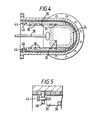
- a slide valve 110 which has an inlet 112, an outlet 116 and a bonnet 120.
- An orifice plate 130 is bolted from below to the internal rim 132 by a plurality of bolts 131.
- the valve guides 126 are bolted to the upper part of the bonnet 120 by a plurality of bolts 127 as shown.
- the valve guides 126 are provided with slots 136 and the areas 126a and 126b are hardfaced to reduce wear caused by the valve disc 124 sliding thereon.
- Each valve guide 126 has a recess 150 extending therealong for receiving and transmitting particulates.
- a slide valve 210 which has an inlet 212, an outlet 216 and a bonnet 220.
- An orifice plate 230 is welded from below to the internal rim 232 by a continuous annular weld 230a which obviates the need for a sealing gasket.
- the valve guides 226 are bolted to the upper part of the bonnet 220 by a plurality of bolts 227 as shown.
- the valve guides 226 are provided with slots 236 and the areas 226a and 226b are hardfaced to reduce wear caused by the valve disc 224 sliding thereon.
- Each valve guide 226 has a recess 250 extending therealong for receiving and transmitting particulates.
- the slide valve 310 shown in Figures 12 to 14 has a removable guide and orifice plate assembly that includes valve guides 326 and an extended orifice plate 330.
- valve guides 326 Once the valve guides 326 have been bolted to the orifice plate 330 with bolts 327 the complete assembly can be installed in the valve 310 as a unit through the bonnet 320 and bolted to the internal rim 332 by bolts 331. The unit may also be bolted to the bonnet 320 if desired.
- Each valve guide 326 has a recess 350 which communicates with a series of slots 336 through which particulates can fall.
Landscapes
- Engineering & Computer Science (AREA)
- General Engineering & Computer Science (AREA)
- Mechanical Engineering (AREA)
- Sliding Valves (AREA)
- Filling Or Emptying Of Bunkers, Hoppers, And Tanks (AREA)
- Check Valves (AREA)
Applications Claiming Priority (2)
| Application Number | Priority Date | Filing Date | Title |
|---|---|---|---|
| US06/839,003 US4693452A (en) | 1986-03-12 | 1986-03-12 | Valve |
| US839003 | 1997-04-23 |
Publications (2)
| Publication Number | Publication Date |
|---|---|
| EP0237244A2 true EP0237244A2 (fr) | 1987-09-16 |
| EP0237244A3 EP0237244A3 (fr) | 1988-04-20 |
Family
ID=25278613
Family Applications (1)
| Application Number | Title | Priority Date | Filing Date |
|---|---|---|---|
| EP87301813A Withdrawn EP0237244A3 (fr) | 1986-03-12 | 1987-03-02 | Vanne d'arrêt |
Country Status (3)
| Country | Link |
|---|---|
| US (1) | US4693452A (fr) |
| EP (1) | EP0237244A3 (fr) |
| JP (1) | JPS62220776A (fr) |
Cited By (4)
| Publication number | Priority date | Publication date | Assignee | Title |
|---|---|---|---|---|
| EP0584453A1 (fr) * | 1992-05-23 | 1994-03-02 | Abel GmbH & Co. Handels- + Verwaltungsgesellschaft | Pompe pour matériaux solides |
| DE102006028508A1 (de) * | 2006-06-21 | 2007-12-27 | Z & J Technologies Gmbh | Schieberventil |
| DE102006037290B4 (de) * | 2006-02-06 | 2008-05-08 | Z & J Technologies Gmbh | Schieberventil |
| WO2021116720A1 (fr) * | 2019-12-12 | 2021-06-17 | Szinay Zoltan | Appareil et procédé pour travailler des grains/copeaux de plastique par craquage thermique |
Families Citing this family (19)
| Publication number | Priority date | Publication date | Assignee | Title |
|---|---|---|---|---|
| JPH01128068U (fr) * | 1988-02-25 | 1989-08-31 | ||
| US5123440A (en) * | 1991-02-11 | 1992-06-23 | Houston James L | Slide valve |
| US5301712A (en) * | 1993-07-12 | 1994-04-12 | Tapco International, Inc. | Slide valve |
| US5706852A (en) * | 1995-10-03 | 1998-01-13 | Deville; Wayne E. | Multi-orifice plate carrier and fitting with positioner, differential selector and horizontal adjusting bar |
| JP2002509229A (ja) * | 1998-01-15 | 2002-03-26 | タプコ インタナシャナル,インコーポレイテッド | 内部を溶接したスライド弁 |
| US6050288A (en) * | 1998-01-15 | 2000-04-18 | Tapco International, Inc. | Slide valve with welded internals |
| US6109590A (en) | 1998-02-12 | 2000-08-29 | Tapco International, Inc. | Iron ore slide valve with internal support clamp |
| US7316762B2 (en) | 2003-04-11 | 2008-01-08 | Curtiss-Wright Flow Control Corporation | Dynamic flange seal and sealing system |
| US7117959B2 (en) * | 2004-04-22 | 2006-10-10 | Curtiss-Wright Flow Control Corporation | Systems and methods for remotely determining and changing cutting modes during decoking |
| US7931044B2 (en) * | 2006-03-09 | 2011-04-26 | Curtiss-Wright Flow Control Corporation | Valve body and condensate holding tank flushing systems and methods |
| US7628381B2 (en) * | 2007-03-23 | 2009-12-08 | Itt Manufacturing Enterprises, Inc. | Method for replacing seals in recreational vehicles gate valves without removing valve housing from plumbing |
| GB201112885D0 (en) * | 2011-07-26 | 2011-09-07 | Sasol Tech Pty Ltd | Solids-handling equipment |
| JP5984614B2 (ja) | 2012-10-15 | 2016-09-06 | 株式会社クボタ | 高温用仕切弁 |
| EP3283852B1 (fr) * | 2015-04-17 | 2020-05-06 | Daniel Measurement and Control, Inc. | Guide de support de plaque pour raccord à orifice |
| ITUB20153096A1 (it) * | 2015-08-13 | 2017-02-13 | Lombardini Srl | Sistema di pressurizzazione per componenti di un motore di un veicolo per la protezione dall'acqua |
| CN107573972B (zh) * | 2017-08-03 | 2020-09-08 | 山西潞安煤基合成油有限公司 | 鲁奇气化炉防腐耐磨处理方法 |
| CN108488409A (zh) * | 2018-06-28 | 2018-09-04 | 烟台金泰美林科技股份有限公司 | 滑阀 |
| CN108533774A (zh) * | 2018-07-09 | 2018-09-14 | 烟台金泰美林科技股份有限公司 | 陶瓷滑阀 |
| CA3047469A1 (fr) * | 2019-06-20 | 2020-12-20 | Slurryflo Valve Corporation | Robinet-vanne |
Family Cites Families (38)
| Publication number | Priority date | Publication date | Assignee | Title |
|---|---|---|---|---|
| US2838066A (en) * | 1958-06-10 | Harris | ||
| US3044889A (en) * | 1962-07-17 | Tar-bonded magnesia brick and method | ||
| DE885634C (de) * | 1953-06-25 | Passavant Werke | Absperrvorrichtung, besonders fuer Fluessigkeitsleitungen | |
| US1980495A (en) * | 1931-04-16 | 1934-11-13 | James F Muir | Valve |
| US2636712A (en) * | 1950-04-03 | 1953-04-28 | Standard Oil Dev Co | Slide valve for regulating the flow of solids |
| FR1094888A (fr) * | 1953-03-27 | 1955-05-25 | Vanne à passage direct pour l'acheminement de fluides | |
| US2696967A (en) * | 1953-09-22 | 1954-12-14 | Robert K Wilson | Fluid seal construction |
| US2787438A (en) * | 1954-03-29 | 1957-04-02 | Exxon Research Engineering Co | Slide valve structure |
| US2815187A (en) * | 1954-08-02 | 1957-12-03 | Leland S Hamer | Sealed gate valve |
| US2998957A (en) * | 1959-01-26 | 1961-09-05 | Vulliez Paul | Arrangement for fitting a self-centering cover without any clearance on valves and the like parts |
| US3197528A (en) * | 1962-04-11 | 1965-07-27 | Howe Sound Co | Method of constructing furnace parts |
| US3111137A (en) * | 1962-05-24 | 1963-11-19 | Carlin Bernard | Gate valve |
| US3232577A (en) * | 1963-05-10 | 1966-02-01 | Frank T Sargent | Gate valve with sectional body |
| AT260089B (de) * | 1965-07-08 | 1968-02-12 | Veitscher Magnesitwerke Ag | Verfahren und Preßform zur Herstellung von feuerfesten, eine flache Auflage besitzenden Steinen und nach dem Verfahren hergestellte Steine |
| US3654962A (en) * | 1969-10-03 | 1972-04-11 | Otis Eng Co | Valves |
| US3685707A (en) * | 1970-05-01 | 1972-08-22 | United States Steel Corp | Sliding-gate closure for bottom-pour vessel |
| US3746305A (en) * | 1970-12-08 | 1973-07-17 | J Zakka | Interchangeable valve seat assembly |
| US3726306A (en) * | 1971-05-20 | 1973-04-10 | Texas Alloy Prod Co | Refinery control valve |
| US3866806A (en) * | 1973-03-01 | 1975-02-18 | United States Steel Corp | Operating mechanism for slidable gates and method of operating slide gate |
| US3842861A (en) * | 1973-09-27 | 1974-10-22 | Tapco Int Inc | Double disc seal valve |
| DE2364904C2 (de) * | 1973-12-28 | 1979-02-08 | Claudius Peters Ag, 2000 Hamburg | Absperrorgan für eine schleißendes Gut führende Leitung |
| GB1490981A (en) * | 1974-01-15 | 1977-11-09 | Flogates Ltd | Pouring of molten metals |
| US3972504A (en) * | 1974-12-02 | 1976-08-03 | Ametek, Inc. | Main steam isolation check valve |
| US3964507A (en) * | 1975-01-13 | 1976-06-22 | Tapco International, Inc. | Slide valve with integrated removable internals |
| US3976094A (en) * | 1975-01-13 | 1976-08-24 | Tapco International, Inc. | Guided slide valve |
| CH600223A5 (fr) * | 1975-07-01 | 1978-06-15 | Vat Ag | |
| GB1593371A (en) * | 1976-06-25 | 1981-07-15 | Didier Werke Ag | Refractory structures |
| DE2714933C3 (de) * | 1977-04-02 | 1981-02-26 | Guenter 5650 Solingen Burgmer | Flachschieber |
| SU624041A1 (ru) * | 1977-04-06 | 1978-09-15 | Demchenko Aleksej F | Шиберный затвор |
| US4554035A (en) * | 1977-10-17 | 1985-11-19 | General Refractories Company | Method of manufacturing a slide gate |
| US4253487A (en) * | 1978-11-13 | 1981-03-03 | Exxon Research & Engineering Co. | Multi-position dual disc slide valve |
| US4292992A (en) * | 1979-07-23 | 1981-10-06 | Allis-Chalmers Corporation | Valve for handling solids capable of gas-pressure-tight closure against a gas pressure differential |
| US4316483A (en) * | 1979-08-09 | 1982-02-23 | Tapco International, Inc. | Valve having wear-prone parts removable through bonnet area |
| US4331316A (en) * | 1980-11-21 | 1982-05-25 | General Signal Corporation | Shut-off valve for high temperature erosive flow |
| US4531539A (en) * | 1981-11-23 | 1985-07-30 | General Signal Corporation | Control valve for flow of solids |
| US4458879A (en) * | 1982-07-12 | 1984-07-10 | General Signal Corporation | Valve |
| US4512363A (en) * | 1982-08-25 | 1985-04-23 | General Signal Corporation | Slide valve |
| US4518146A (en) * | 1983-04-28 | 1985-05-21 | General Signal Corporation | Valve operator control system |
-
1986
- 1986-03-12 US US06/839,003 patent/US4693452A/en not_active Expired - Lifetime
-
1987
- 1987-03-02 EP EP87301813A patent/EP0237244A3/fr not_active Withdrawn
- 1987-03-11 JP JP62056418A patent/JPS62220776A/ja active Pending
Cited By (4)
| Publication number | Priority date | Publication date | Assignee | Title |
|---|---|---|---|---|
| EP0584453A1 (fr) * | 1992-05-23 | 1994-03-02 | Abel GmbH & Co. Handels- + Verwaltungsgesellschaft | Pompe pour matériaux solides |
| DE102006037290B4 (de) * | 2006-02-06 | 2008-05-08 | Z & J Technologies Gmbh | Schieberventil |
| DE102006028508A1 (de) * | 2006-06-21 | 2007-12-27 | Z & J Technologies Gmbh | Schieberventil |
| WO2021116720A1 (fr) * | 2019-12-12 | 2021-06-17 | Szinay Zoltan | Appareil et procédé pour travailler des grains/copeaux de plastique par craquage thermique |
Also Published As
| Publication number | Publication date |
|---|---|
| JPS62220776A (ja) | 1987-09-28 |
| US4693452A (en) | 1987-09-15 |
| EP0237244A3 (fr) | 1988-04-20 |
Similar Documents
| Publication | Publication Date | Title |
|---|---|---|
| EP0237244A2 (fr) | Vanne d'arrêt | |
| US4253487A (en) | Multi-position dual disc slide valve | |
| US4798365A (en) | Throttling gasket insert for use with knife gate valve | |
| CA1202176A (fr) | Panneau a refroidissement pulse pour le chemisage d'un four de metallurgie | |
| GB1587875A (en) | Multi-position disc slide valve | |
| EP0070910A1 (fr) | Valve pour un matériau granuleux à fermeture étanche contre la pression différentielle d'un gaz | |
| JPS61153500A (ja) | 板形熱交換器 | |
| WO2000011379A1 (fr) | Joint de compression de ressort | |
| US5895028A (en) | Single disc slide valve with center biased flow | |
| AU652528B2 (en) | Recirculation valve | |
| EP1558889B1 (fr) | Echangeur de chaleur pourvu d'un moyen de renforcement | |
| US3937247A (en) | Valve for fluids containing abrasive particles | |
| EP1982098A2 (fr) | Valve d'orifice pour solides en vrac | |
| GB2275545A (en) | Diverting fluid flow | |
| WO1996003207A1 (fr) | Element pour plaque de support sans soudures | |
| US7287575B2 (en) | Component for supporting a filter member, a device including a tubular filter member and said component, a plate heat exchanger including a tubular filter member and said component | |
| US4325428A (en) | Heat exchanger | |
| US4479743A (en) | Wear resistant insert for particulate material flow ducts | |
| CN104204706A (zh) | 板式换热器 | |
| US4074691A (en) | Open shroud trickle valve | |
| EP0417071B1 (fr) | Agencement servant a empecher l'ecoulement a travers un orifice dans un echangeur de chaleur a plaques | |
| EP0460794B1 (fr) | Vanne de distribution | |
| US7195057B2 (en) | Plate heat exchanger and end plate associated therewith | |
| CA2280168A1 (fr) | Cuve pour la metallurgie | |
| US3955950A (en) | Cyclone vessel hanger system |
Legal Events
| Date | Code | Title | Description |
|---|---|---|---|
| PUAI | Public reference made under article 153(3) epc to a published international application that has entered the european phase |
Free format text: ORIGINAL CODE: 0009012 |
|
| AK | Designated contracting states |
Kind code of ref document: A2 Designated state(s): DE FR GB |
|
| PUAL | Search report despatched |
Free format text: ORIGINAL CODE: 0009013 |
|
| AK | Designated contracting states |
Kind code of ref document: A3 Designated state(s): DE FR GB |
|
| 17P | Request for examination filed |
Effective date: 19881011 |
|
| STAA | Information on the status of an ep patent application or granted ep patent |
Free format text: STATUS: THE APPLICATION HAS BEEN WITHDRAWN |
|
| 18W | Application withdrawn |
Withdrawal date: 19890502 |
|
| R18W | Application withdrawn (corrected) |
Effective date: 19890502 |
|
| RIN1 | Information on inventor provided before grant (corrected) |
Inventor name: JANDRASI, FRANK J. |