EP0237296A2 - Magnetisch verriegelte und stromempfindliche automatisch entriegelnde Schalteranordnung - Google Patents
Magnetisch verriegelte und stromempfindliche automatisch entriegelnde Schalteranordnung Download PDFInfo
- Publication number
- EP0237296A2 EP0237296A2 EP87301964A EP87301964A EP0237296A2 EP 0237296 A2 EP0237296 A2 EP 0237296A2 EP 87301964 A EP87301964 A EP 87301964A EP 87301964 A EP87301964 A EP 87301964A EP 0237296 A2 EP0237296 A2 EP 0237296A2
- Authority
- EP
- European Patent Office
- Prior art keywords
- current
- switch
- contact
- coils
- coil
- Prior art date
- Legal status (The legal status is an assumption and is not a legal conclusion. Google has not performed a legal analysis and makes no representation as to the accuracy of the status listed.)
- Withdrawn
Links
- 230000005291 magnetic effect Effects 0.000 claims abstract description 33
- 230000004907 flux Effects 0.000 claims abstract description 23
- 230000005294 ferromagnetic effect Effects 0.000 claims description 8
- 230000000694 effects Effects 0.000 abstract description 4
- 238000013459 approach Methods 0.000 description 4
- 238000010586 diagram Methods 0.000 description 2
- 229910052751 metal Inorganic materials 0.000 description 2
- 230000002441 reversible effect Effects 0.000 description 2
- 230000000712 assembly Effects 0.000 description 1
- 238000000429 assembly Methods 0.000 description 1
- 230000004888 barrier function Effects 0.000 description 1
- 238000010276 construction Methods 0.000 description 1
- 230000000994 depressogenic effect Effects 0.000 description 1
- 230000000284 resting effect Effects 0.000 description 1
Images



Classifications
-
- H—ELECTRICITY
- H01—ELECTRIC ELEMENTS
- H01H—ELECTRIC SWITCHES; RELAYS; SELECTORS; EMERGENCY PROTECTIVE DEVICES
- H01H71/00—Details of the protective switches or relays covered by groups H01H73/00 - H01H83/00
- H01H71/10—Operating or release mechanisms
- H01H71/12—Automatic release mechanisms with or without manual release
- H01H71/24—Electromagnetic mechanisms
- H01H71/26—Electromagnetic mechanisms with windings acting in opposition
-
- H—ELECTRICITY
- H01—ELECTRIC ELEMENTS
- H01H—ELECTRIC SWITCHES; RELAYS; SELECTORS; EMERGENCY PROTECTIVE DEVICES
- H01H3/00—Mechanisms for operating contacts
- H01H3/32—Driving mechanisms, i.e. for transmitting driving force to the contacts
- H01H3/50—Driving mechanisms, i.e. for transmitting driving force to the contacts with indexing or locating means, e.g. indexing by ball and spring
-
- H—ELECTRICITY
- H01—ELECTRIC ELEMENTS
- H01H—ELECTRIC SWITCHES; RELAYS; SELECTORS; EMERGENCY PROTECTIVE DEVICES
- H01H3/00—Mechanisms for operating contacts
- H01H3/32—Driving mechanisms, i.e. for transmitting driving force to the contacts
- H01H3/50—Driving mechanisms, i.e. for transmitting driving force to the contacts with indexing or locating means, e.g. indexing by ball and spring
- H01H3/503—Driving mechanisms, i.e. for transmitting driving force to the contacts with indexing or locating means, e.g. indexing by ball and spring making use of electromagnets
Definitions
- This invention relates to an electrical switch assembly and, more particularly, to such an assembly which may be used in an automobile to automatically control the raising or lowering of a window to an extreme position thereof in response to a momentary operation of the switch assembly actuator button.
- a straightforward approach is to utilize limit switches for sensing travel of the window to an extreme position.
- This approach is unsatisfactory in that it requires additional parts, thereby significantly increasing the cost.
- Other approaches have utilized the principle that the motor will stall when the window reaches its extreme position, which results in an increase in the motor current.
- Some of these approaches have included circuitry for sensing the motor current and opening the current path when the motor current exceeds a predetermined threshold. Again, this is disadvantageous in that it requires additional circuity which increases the cost.
- Still other approaches have utilized a bi-metallic element which opens the switch when it is heated by excessive motor current flowing therethrough.
- the latch includes a frame having first and second coils wound thereabout.
- the coils are connected in series so that current passing through the coils causes the coils to produce oppositely directed magnetic flux in the frame.
- the coils are arranged so that, for a given current, the first coil generates a greater magnetic flux than the second coil and the net magnetic flux generated in response to the normal motor running current is sufficient to provide a latching effect for the switch.
- Means are provided which are responsive to the motor current exceeding a predetermined threshold for diverting a portion of the current from the first coil while allowing it to pass through the second coil so as to reduce the net magnetic flux and terminate the latching effect.
- the diverting means includes a diode connected across the first coil and poled in the direction of the current.
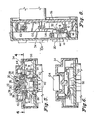
- the latching switch assembly includes a movable switch blade l0 having, illustratively, four switch contacts l2, l4, l6 and l8 thereon.
- the switch blade l0 is affixed to the movable actuator button 20 by means of the knurled pin 22 which extends through the hole 24 of the switch blade l0 and into the bore 26 provided therefor in the boss 28 which is molded as part of the button 20.
- the pin 22 and the bore 26 are sized to provide for a press fit engagement therebetween.
- the boss 28 is inserted through the bore 30 of the boss 32 molded as part of the cover 34 of the overall switch unit.
- a spring 36 has one end resting on the shoulder 38 of the boss 32 and its other end bearing against the underside of the actuator button 20 so as to provide a resiliently yieldable biasing force on the button 20 in a direction to move the button 20 away from the cover 34.
- a fixed contact 40 mounted on the bus bar 42.
- a fixed contact 44 mounted on the bus bar 46.
- a fixed contact 48 mounted on the bus bar 50.
- a fixed contact 52 mounted on the bus bar 54.
- the bus bars 42 and 46 are supported by the cover 34 of the switch unit and the bus bars 50 and 54 are supported on the base 56 of the switch unit, as shown in FIG. 5. Accordingly, due to the action of the spring 36, the switch blade l0 is biased away from the fixed contacts 48 and 52 and normally bridges the fixed contacts 40 and 44.
- a magnetic frame illustratively a U-shaped ferromagnetic yoke member 58 having legs 60 for securing the yoke member 58 on the base 56.
- a first coil of wire 62 is wound about an arm 64 of the yoke member 58 and a second coil of wire 66 is wound about the other arm 68 of the yoke member 58.
- the coils 62 and 66 are wound about their respective arms 64 and 68 in appropriate directions so that current passing serially through the coils 62 and 66 generates oppositely directed magnetic flux in the yoke 58.
- a ferromagnetic latch plate 70 is provided to cooperate with the ends of the yoke arms 64 and 68 to complete a magnetic circuit when the coils 62 and 66 are energized.
- the latch plate 70 is provided with a centrally located hole 72 sized to accommodate the pin 22 therethrough.
- the latch plate 70 is positioned between the switch blade l0 and the boss 28 so that, when assembled, the actuator button 20, the latch plate 70, the switch blade l0 and the pin 22 move together.
- the upstanding tabs 74 on the switch blade l0 prevent relative rotation between the switch blade l0 and the latch plate 70.
- a diode 76 having its anode 88 supported by the bifurcated tab 78 of the bus bar 94.
- the first end 80 of the first coil 62 and the first end 82 of the second coil 66 are connected together and to the cathode 84 of the diode 76.
- the second end 86 of the first coil 62 is connected to the anode 88 of the diode 76.
- the second end 90 of the second coil 66 is connected to the tab 92 of the bus bar 50, and hence to the fixed contact 48.
- FIG. 2 illustrates the operation of this latching/unlatching switch assembly.
- the connection of the first coil 62 and the anode 88 of the diode 76 on the bus bar 94 is to the positive battery supply.
- the fixed contact 52 is connected to one side of the motor 96, the other side of which is connected to ground.
- the coils 62 and 66 are so arranged that when the normal motor run current flows therethrough, more magnetic flux is generated by the coil 62; but at the same time, the net magnetic flux generated by the coils 62 and 66 is sufficient to create a magnetic attractive force between the yoke member 58 and the latch plate 70 that overcomes the restoring force of the spring 36. Accordingly, the switch blade l0 continues to bridge the contacts 48 and 52.
- the normal running current of the motor 96 through the coil 62 generates a voltage drop across the coil 62 which is insufficient to cause the diode 76 to fully conduct.
- the motor 96 has a run current of 3.5 amps and a stall current of l5 amps.
- An illustrative diode 76 is a type lN5820 Schottky barrier rectifier manufactured by Motorola. With such an arrangement, it has been found that at the motor run current sufficient magnetic flux is generated that the latch will hold a l l/4 lb. load.
- FIG. 3 illustrates the latching switch assembly described hereinabove when used with a reversible motor 98 and a momentary contact switch l00 for driving the motor 98 in a first direction and a momentary contact switch l02 for driving the motor 98 in a second direction.
- the latching switch assembly is operative to drive the motor 98 in the first direction until it reaches a stall condition.
- the switches l00 and l02 are normally as shown by the respective solid lines but by momentary operation thereof may be moved to the positions shown by the respective broken lines. Thus, in the normal unoperated condition shown in FIG. 3, there is no current through the motor 98.
- switch l02 If the switch l02 is momentarily operated, current flows from the positive supply, through the switch l02 as long as it is operated, to the left through the motor 98, through the switch l00, to the contact 40, through the switch blade l0, to the contact 44, and to ground, momentarily driving the motor 98 in a first direction. If the switch l00 is momentarily operated, current flows from the positive supply, through the switch l00 as long as it is operated, through the motor 98 to the right, through the switch l02, and to ground, momentarily driving the motor 98 in a second direction.
- FIGS. 4-8 illustrate a switch unit for implementing the circuit shown in FIG. 3.
- This switch unit includes the latching switch assembly illustrated in FIG. l and the two momentary contact switches l00 and l02, which are illustratively of the snap acting type disclosed in U.S. Patent No. 3,l89,703.
- the momentary contact switches l00 and l02 are controlled by a rocker actuator l04.
- the construction of these momentary contact switches l00 and l02 does not form a part of the present invention. It is understood that although the switch unit disclosed in FIGS.
- latching switch assembly 4-8 only includes one latching switch assembly, it is contemplated that it could be constructed with two latching switch assemblies and two momentary contact switches, with a respective pair comprising a latching switch assembly and a momentary contact switch for driving the motor in a respective direction. It is also contemplated that the disclosed latching switch assembly can be constructed to cooperate with a momentary switch such that initial travel of the actuator only causes closing of the momentary switch and that subsequent overtravel of the actuator causes actuation of the latching switch assembly. It is further contemplated that the latching switch assembly can be constructed with two latching switches which cooperate with a single electromagnetic latch.
Landscapes
- Physics & Mathematics (AREA)
- Electromagnetism (AREA)
- Tumbler Switches (AREA)
- Relay Circuits (AREA)
- Push-Button Switches (AREA)
Applications Claiming Priority (2)
| Application Number | Priority Date | Filing Date | Title |
|---|---|---|---|
| US06/837,450 US4754362A (en) | 1986-03-07 | 1986-03-07 | Magnetically latching and current sensitive automatically unlatching switch assembly |
| US837450 | 1986-03-07 |
Publications (2)
| Publication Number | Publication Date |
|---|---|
| EP0237296A2 true EP0237296A2 (de) | 1987-09-16 |
| EP0237296A3 EP0237296A3 (de) | 1989-02-01 |
Family
ID=25274478
Family Applications (1)
| Application Number | Title | Priority Date | Filing Date |
|---|---|---|---|
| EP87301964A Withdrawn EP0237296A3 (de) | 1986-03-07 | 1987-03-06 | Magnetisch verriegelte und stromempfindliche automatisch entriegelnde Schalteranordnung |
Country Status (5)
| Country | Link |
|---|---|
| US (1) | US4754362A (de) |
| EP (1) | EP0237296A3 (de) |
| JP (1) | JPS62223916A (de) |
| AU (1) | AU6980187A (de) |
| CA (1) | CA1264175A (de) |
Cited By (3)
| Publication number | Priority date | Publication date | Assignee | Title |
|---|---|---|---|---|
| US4984123A (en) * | 1989-07-17 | 1991-01-08 | Potter & Brumfield, Inc. | Latching switching device having current responsive release |
| EP2192605A1 (de) * | 2008-11-28 | 2010-06-02 | Alstom Transport S.A. | Trennvorrichtung eines elektrischen Schaltkreises und Stromverteilungskasten, der mit einer solchen Trennvorrichtung ausgestattet ist |
| WO2012146876A1 (fr) * | 2011-04-29 | 2012-11-01 | Hager-Electro Sas | Actionneur électromagnétique à générateur magnétique |
Families Citing this family (5)
| Publication number | Priority date | Publication date | Assignee | Title |
|---|---|---|---|---|
| US5040089A (en) * | 1986-11-26 | 1991-08-13 | Kabushiki Kaisha Toshiba | D.C. relay with power reducing function |
| US5256921A (en) * | 1992-06-03 | 1993-10-26 | Harry Pruis | Gear motor with rotary switch |
| US5737968A (en) * | 1996-05-07 | 1998-04-14 | Hardey; Donald H. | Integrated gear motor and method of assembly |
| WO2019123829A1 (ja) * | 2017-12-22 | 2019-06-27 | アルプスアルパイン株式会社 | スイッチ装置 |
| CN114068211B (zh) * | 2021-11-03 | 2024-07-30 | 珠海优特电力科技股份有限公司 | 电气锁具 |
Family Cites Families (11)
| Publication number | Priority date | Publication date | Assignee | Title |
|---|---|---|---|---|
| US3456125A (en) * | 1967-06-01 | 1969-07-15 | Gen Constr Elect Mec | High speed protective circuit for regulating transistors |
| CH523583A (fr) * | 1971-04-23 | 1972-05-31 | Lucifer Sa | Dispositif de commande d'un électro-aimant |
| US3683239A (en) * | 1971-06-17 | 1972-08-08 | Oded E Sturman | Self-latching solenoid actuator |
| JPS5468534A (en) * | 1977-11-11 | 1979-06-01 | Iida Sankyo | Safety device for liquid fuel |
| US4227231A (en) * | 1978-09-05 | 1980-10-07 | Eaton Corporation | Integral relay low voltage retentive means |
| JPS641722Y2 (de) * | 1979-07-30 | 1989-01-17 | ||
| JPS6343779Y2 (de) * | 1980-05-19 | 1988-11-15 | ||
| US4451865A (en) * | 1981-05-18 | 1984-05-29 | The Singer Company | Electrical cutout for under voltage or power loss conditions |
| EP0065852B1 (de) * | 1981-05-22 | 1988-08-24 | LUCAS INDUSTRIES public limited company | Relaisschaltung und Relais dafür |
| DE3211497A1 (de) * | 1982-03-29 | 1983-10-06 | Siemens Ag | Schaltungsanordnung zum selbsttaetigen schliessen einer ersatzweisen fernspeiseschleife |
| JPS603817A (ja) * | 1983-06-20 | 1985-01-10 | 株式会社東海理化電機製作所 | モ−タ制御用スイツチ装置 |
-
1986
- 1986-03-07 US US06/837,450 patent/US4754362A/en not_active Expired - Lifetime
-
1987
- 1987-03-03 CA CA000531052A patent/CA1264175A/en not_active Expired
- 1987-03-06 AU AU69801/87A patent/AU6980187A/en not_active Abandoned
- 1987-03-06 EP EP87301964A patent/EP0237296A3/de not_active Withdrawn
- 1987-03-06 JP JP62051862A patent/JPS62223916A/ja active Pending
Cited By (6)
| Publication number | Priority date | Publication date | Assignee | Title |
|---|---|---|---|---|
| US4984123A (en) * | 1989-07-17 | 1991-01-08 | Potter & Brumfield, Inc. | Latching switching device having current responsive release |
| EP2192605A1 (de) * | 2008-11-28 | 2010-06-02 | Alstom Transport S.A. | Trennvorrichtung eines elektrischen Schaltkreises und Stromverteilungskasten, der mit einer solchen Trennvorrichtung ausgestattet ist |
| FR2939237A1 (fr) * | 2008-11-28 | 2010-06-04 | Alstom Transport Sa | Dispositif de sectionnement d'un circuit electrique et coffret de distribution d'energie electrique comprenant un tel dispositif de sectionnement. |
| US8319587B2 (en) | 2008-11-28 | 2012-11-27 | Alstom Transport Sa | Device for sectioning an electrical circuit and a system for distributing electrical energy including the sectioning device |
| WO2012146876A1 (fr) * | 2011-04-29 | 2012-11-01 | Hager-Electro Sas | Actionneur électromagnétique à générateur magnétique |
| FR2974662A1 (fr) * | 2011-04-29 | 2012-11-02 | Hager Electro Sas | Actionneur electromagnetique a generateur magnetique |
Also Published As
| Publication number | Publication date |
|---|---|
| JPS62223916A (ja) | 1987-10-01 |
| CA1264175A (en) | 1990-01-02 |
| AU6980187A (en) | 1987-09-10 |
| US4754362A (en) | 1988-06-28 |
| EP0237296A3 (de) | 1989-02-01 |
Similar Documents
| Publication | Publication Date | Title |
|---|---|---|
| US6025766A (en) | Trip mechanism for an overload relay | |
| US5532660A (en) | Manual override mechanism for a remote controlled circuit breaker | |
| JPS59189527A (ja) | 電流しや断器 | |
| DE102012006438A1 (de) | Relais mit zwei gegensinnig betätigbaren Schaltern | |
| US4754362A (en) | Magnetically latching and current sensitive automatically unlatching switch assembly | |
| US5332986A (en) | Overload relay mechanism | |
| US4376896A (en) | Switching assembly | |
| US5910759A (en) | Contact mechanism for electronic overload relays | |
| US7012795B2 (en) | Electromagnetic circuit breaker assembly having reverse polarity protection | |
| SE466674B (sv) | Brytarapparat med fjaerrstyrning | |
| JPS6394527A (ja) | 電磁リレ− | |
| EP1078384B1 (de) | Kontaktmechanismus für elektronisches schutzrelais | |
| US4884049A (en) | Circuit breaker overcurrent tripping device | |
| EP0860843B1 (de) | Schutzschalter | |
| JPS6367304B2 (de) | ||
| US5939961A (en) | Electric safety locking device | |
| EP0225236A1 (de) | Elektromagnetisches Relais | |
| US5181001A (en) | Remotely-controlled relay | |
| EP0458301A2 (de) | Ferngesteuertes Relais | |
| JPH04233120A (ja) | 過負荷継電器 | |
| EP1367617A1 (de) | Lasttrennschalter, insbesondere für den Laststromkreis einer Fahrzeugbatterie | |
| JPH0142275Y2 (de) | ||
| KR200224240Y1 (ko) | 전자접촉기의 래치장치 | |
| JPH0142274Y2 (de) | ||
| JPH0728665Y2 (ja) | 電磁継電器 |
Legal Events
| Date | Code | Title | Description |
|---|---|---|---|
| PUAI | Public reference made under article 153(3) epc to a published international application that has entered the european phase |
Free format text: ORIGINAL CODE: 0009012 |
|
| AK | Designated contracting states |
Kind code of ref document: A2 Designated state(s): DE ES FR GB IT |
|
| PUAL | Search report despatched |
Free format text: ORIGINAL CODE: 0009013 |
|
| AK | Designated contracting states |
Kind code of ref document: A3 Designated state(s): DE ES FR GB IT |
|
| STAA | Information on the status of an ep patent application or granted ep patent |
Free format text: STATUS: THE APPLICATION IS DEEMED TO BE WITHDRAWN |
|
| 18D | Application deemed to be withdrawn |
Effective date: 19890802 |
|
| ITF | It: translation for a ep patent filed | ||
| RIN1 | Information on inventor provided before grant (corrected) |
Inventor name: BELLER, WILBERT ERWIN |