EP0237708A1 - Dispositif d'aspiration dentaire - Google Patents
Dispositif d'aspiration dentaire Download PDFInfo
- Publication number
- EP0237708A1 EP0237708A1 EP87100374A EP87100374A EP0237708A1 EP 0237708 A1 EP0237708 A1 EP 0237708A1 EP 87100374 A EP87100374 A EP 87100374A EP 87100374 A EP87100374 A EP 87100374A EP 0237708 A1 EP0237708 A1 EP 0237708A1
- Authority
- EP
- European Patent Office
- Prior art keywords
- liquid
- pump
- air
- suction device
- cyclone
- Prior art date
- Legal status (The legal status is an assumption and is not a legal conclusion. Google has not performed a legal analysis and makes no representation as to the accuracy of the status listed.)
- Granted
Links
- 239000000203 mixture Substances 0.000 claims abstract description 29
- 239000007788 liquid Substances 0.000 claims description 88
- 238000000926 separation method Methods 0.000 claims description 27
- 238000004062 sedimentation Methods 0.000 claims description 16
- 230000005484 gravity Effects 0.000 claims description 5
- 238000011144 upstream manufacturing Methods 0.000 claims description 2
- 239000006260 foam Substances 0.000 abstract description 8
- 239000012530 fluid Substances 0.000 abstract 5
- 239000003570 air Substances 0.000 description 28
- 239000002245 particle Substances 0.000 description 11
- 238000011161 development Methods 0.000 description 9
- 230000018109 developmental process Effects 0.000 description 9
- 229910000497 Amalgam Inorganic materials 0.000 description 8
- 239000007787 solid Substances 0.000 description 7
- 230000002093 peripheral effect Effects 0.000 description 6
- XLYOFNOQVPJJNP-UHFFFAOYSA-N water Substances O XLYOFNOQVPJJNP-UHFFFAOYSA-N 0.000 description 5
- 239000000470 constituent Substances 0.000 description 4
- 239000010865 sewage Substances 0.000 description 4
- 239000010802 sludge Substances 0.000 description 4
- 230000033001 locomotion Effects 0.000 description 3
- 230000001914 calming effect Effects 0.000 description 2
- 239000013049 sediment Substances 0.000 description 2
- 238000003466 welding Methods 0.000 description 2
- VEUMANXWQDHAJV-UHFFFAOYSA-N 2-[2-[(2-hydroxyphenyl)methylideneamino]ethyliminomethyl]phenol Chemical compound OC1=CC=CC=C1C=NCCN=CC1=CC=CC=C1O VEUMANXWQDHAJV-UHFFFAOYSA-N 0.000 description 1
- 239000008280 blood Substances 0.000 description 1
- 210000004369 blood Anatomy 0.000 description 1
- 238000005119 centrifugation Methods 0.000 description 1
- 238000010276 construction Methods 0.000 description 1
- 238000001816 cooling Methods 0.000 description 1
- 239000000498 cooling water Substances 0.000 description 1
- 230000000694 effects Effects 0.000 description 1
- 238000010616 electrical installation Methods 0.000 description 1
- 238000002347 injection Methods 0.000 description 1
- 239000007924 injection Substances 0.000 description 1
- 238000009434 installation Methods 0.000 description 1
- 239000000463 material Substances 0.000 description 1
- 239000008213 purified water Substances 0.000 description 1
- 230000000717 retained effect Effects 0.000 description 1
- 239000008237 rinsing water Substances 0.000 description 1
- -1 saliva Substances 0.000 description 1
- 210000003296 saliva Anatomy 0.000 description 1
Images




Classifications
-
- B—PERFORMING OPERATIONS; TRANSPORTING
- B04—CENTRIFUGAL APPARATUS OR MACHINES FOR CARRYING-OUT PHYSICAL OR CHEMICAL PROCESSES
- B04C—APPARATUS USING FREE VORTEX FLOW, e.g. CYCLONES
- B04C9/00—Combinations with other devices, e.g. fans, expansion chambers, diffusors, water locks
-
- A—HUMAN NECESSITIES
- A61—MEDICAL OR VETERINARY SCIENCE; HYGIENE
- A61C—DENTISTRY; APPARATUS OR METHODS FOR ORAL OR DENTAL HYGIENE
- A61C17/00—Devices for cleaning, polishing, rinsing or drying teeth, teeth cavities or prostheses; Saliva removers; Dental appliances for receiving spittle
- A61C17/06—Saliva removers; Accessories therefor
- A61C17/12—Control devices, e.g. for suction
-
- B—PERFORMING OPERATIONS; TRANSPORTING
- B04—CENTRIFUGAL APPARATUS OR MACHINES FOR CARRYING-OUT PHYSICAL OR CHEMICAL PROCESSES
- B04C—APPARATUS USING FREE VORTEX FLOW, e.g. CYCLONES
- B04C9/00—Combinations with other devices, e.g. fans, expansion chambers, diffusors, water locks
- B04C2009/005—Combinations with other devices, e.g. fans, expansion chambers, diffusors, water locks with external rotors, e.g. impeller, ventilator, fan, blower, pump
Definitions
- the invention relates to a dental suction device according to the preamble of claim 1.
- the vacuum pump is connected via a hose to a liquid separation cyclone which is spatially separate from it.
- the liquid separated in the cyclone is released to the sewage system via a lock system.
- Such freedom could e.g. win by connecting a liquid pump to the liquid discharge opening of the separating device, by means of which the separated liquid is forcibly conveyed to a higher level.
- the present invention is therefore intended to further develop a dental suction device according to the preamble of claim 1 in such a way that a forced discharge of the liquid separated in the separating device is obtained under excess pressure without the need for an additional drive motor.
- the air / liquid separating device is combined with the vacuum pump to form a unit, and the drive motor provided anyway for moving the rotating pump element of the vacuum pump also rotates a pump impeller, which separates the liquid separated from the supplied liquid-air mixture, which accumulates accumulates lower end of the separator, forcibly discharges.
- the suction device according to the invention can be used both as a central suction device for a plurality of workplaces, as specified in claim 12. But it is also well suited for decentralized installation directly at the workplace, whereby its compact structure and the small number of connections to be made are advantageous.
- the overhung shaft sections are also only short, and the vacuum pump is at a large axial distance from the separating device, so that even if the separating device is briefly overcharged, any liquid that gets into the air outlet opening does not get directly into the vacuum pump.
- solid particles such as amalgam particles can also be separated from the liquid components separated from the original mixture using the drive motor used in the prior art only to operate the vacuum pump, so that they do not get into the sewage system .
- the discharge pump and optionally the centrifuge for separating solid particles continue to run even when the inlet opening of the entire suction unit is temporarily not subjected to negative pressure in order not to suck in any further mixture quantities, since the capacity of the separating device is temporarily exceeded, for example due to splash water supply. Under such operating conditions, air is temporarily drawn in from the surroundings by the vacuum pump via the changeover valve.
- control of the upstream of the inlet of the vacuum pump changeover valve is carried out using the output signal of a liquid level sensor which responds when a predetermined liquid level in the separating device is exceeded.
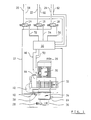
- 10 designates a suction unit, which aspirates and disassembles the mixture of air and liquid (cooling and rinsing water, saliva, blood, etc.) occurring at dental workplaces.
- the mixture is fed to the suction unit via a manifold 12, which can be connected via controllable 2/2 valves 14, 16, 18 to lines 20, 22, 24 leading to the individual workplaces.
- the air portion of the sucked-in mixture is provided by the suction unit 10 at an air outlet nozzle 26, which is usually connected to the building roof-led line is connected.
- the liquid portions of the mixture are provided by the suction unit 10 at a liquid outlet connection 26, which is connected to the sewage system.
- the suction unit has an electric drive motor 30, on the underside of which a vacuum pump 32 is flanged to a known construction, which has, for example, an impeller seated on a pump shaft.
- a liquid separation cyclone denoted overall by 34, which in turn carries a discharge pump 36.
- the liquid separation cyclone 34 has an inlet connection 38 which takes over the mixture supplied from the collecting line 12 and an outlet connection 40 which provides the air freed from liquid and which is connected via a hose section 42 to one of the two inlets of a 3/2-way switch valve 44. Its second input is connected to the ambient atmosphere, its working opening is connected to the suction opening of the vacuum pump 32.
- the changeover valve 44 is controlled via a line 46 from a central control unit 48, which also supplies the drive motor 30 with energy via a line 50.
- the control unit 48 controls the operation of the valves 14, 16, 18 via additional lines 52, 54, 56, specifically as a function of control signals which are transmitted via lines 58, 60, 62 from the individual workstations when suction is required there becomes.
- the control unit 48 is also connected to the output of a level sensor 64, which is carried by the peripheral wall of the liquid separation cyclone 34 and responds when the liquid level in the liquid separation cyclone 34 exceeds a predetermined, maximum permissible value, so that it is no longer guaranteed that the air emitted by the cyclone is completely free of liquid components. Under such conditions, the control unit 48 then switches the changeover valve 44 to the position in which air is drawn in from the ambient atmosphere, while the discharge pump 36 continues to be driven by the drive motor 30.
- control unit 48 brings the changeover valve 44 back into its normal position, in which the vacuum pump 32 is connected to the outlet port 40 of the liquid separation cyclone 34.
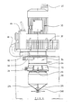
- FIG. 2 shows details of the internal structure of the suction unit 10.
- the shaft 66 of the drive motor 30, which also represents the pump shaft of the vacuum pump 32, is pulled through the liquid separating cyclone 34 and carries at its free end a pump impeller 68 of the discharge pump 36.
- the latter runs in one cup-shaped pump housing 70, which is screwed tightly onto the bottom of the housing of the liquid separation cyclone 34, designated 72.
- the cyclone housing 72 has a conically sloping bottom 74 which carries a central tubular transfer nozzle 76. Its diameter corresponds to the blade-free suction area of the pump impeller 68 and ends at a short axial distance above the latter.
- the pump impeller 68 injection molded from plastic has a raised hub section 78, via which it is clamped to the shaft 66 by means of a screw 82 with the interposition of a propeller hub section 80.
- the propeller hub section 80 belongs to a propeller, designated overall by 84, which also has a transver salen disc section 86 and a plurality of circumferentially distributed propeller blades 88.
- the latter run in a downwardly open channel 90 which is delimited by a bell-shaped deflector section 92 and a tubular connecting piece 94 coaxial therewith.
- the latter fixed parts of the cyclone housing 72 are molded onto a bottom 96 of a cup-shaped housing head part 98, which delimits an outlet chamber 100 which is connected to the air outlet nozzle 40.
- the housing head part 98 is screwed tightly to the cyclone housing 72.
- the inlet connection 40 for the air / liquid mixture opens directly below the bottom 96 of the housing head part 98 into the peripheral wall of the cyclone housing 72 and is thus connected to the annular space 102, which is between the outside of the deflector section 92 and the peripheral wall of the cyclone housing 72 lies.
- the suction unit shown in Figure 2 works as follows:
- the drive motor 30 rotates the fan wheel of the vacuum pump 32, the propeller 84 and the pump impeller 68 together, since these parts are all seated on the shaft 66. Due to the negative pressure generated by the vacuum pump 32, the air / liquid mixture is drawn into the inlet connector 38 and, due to its off-center introduction, passes through the interior of the liquid separation cyclone 34 on a helical path. During this movement, the heavier liquid constituents are separated from the mixture by centrifugal force and flow under the action of gravity over the conical cyclone bottom and the transfer nozzle 76 into the discharge pump 36. The separated liquid components of the mixture are pressed into the liquid outlet nozzle 28 by its pump impeller 68.
- the deflector section 92 prevents parts of the incoming air / liquid mixture from being able to reach the nozzle 94 and from there into the outlet chamber 100.
- Foam contained in the mixture supplied for example due to foam-forming constituents, likewise cannot get into the connection piece 94, since it has to cross the propeller 84 in this way.
- the foam is broken up mechanically, and the propeller 84 also sets it in very strong, rapid rotation, so that further liquid separation takes place by centrifugal force.
- This separation is also particularly effective because the propeller 84 rotates in a direction of rotation that is opposite to the direction of rotation of the helical path of the mixture through the liquid separation cyclone 34. From the inside of the cyclone housing, only air that has been completely freed of liquid constituents passes through the propeller 84 to the nozzle 94 and from there into the outlet chamber 100.
- suction unit 10 has very compact dimensions and only three flow connections are to be made at the place of use, namely those to the manifold 12, the one on the air outlet connector 26 and the one on the liquid outlet connector 28. Only a few connections need to be made for the electrical installation.
- the drive motor 30 is used for three different purposes: the generation of the negative pressure, the forced discharge of the separated liquid by the discharge pump 36 and the smashing and centrifuging of foam components of the sucked-in mixture by the propeller 84.
- FIG. 3 components of the suction unit 10, which have already been explained above with reference to FIGS. 1 and 2, are again provided with the same reference numerals. These components are not described again in detail.
- the pump impeller is designed as part of an overflow centrifuge drum which serves to separate amalgam particles from the liquid separated from the mixture.
- pump vanes 104 which are placed on the upper end face of an annular upper locking flange 106 of a centrifuge drum, generally designated 108, form a pump impeller for the forced discharge of the separated liquid.
- the centrifuge drum 108 has a cylindrical circumferential wall 110, at the upper end of which the locking flange 106 is attached, projecting radially inwards, and a conically sloping bottom 112, which is connected to a hub section 116 via a plurality of circumferentially distributed radial vanes 114. The latter is again clamped to the shaft 66 by means of the screw 82 with the propeller 84 interposed.
- a central portion of the bottom 112 of the centrifuge drum 108 carries a conical, downwardly tapering transfer and return nozzle 118 which projects into a sedimentation chamber 120 which is located below the centrifuge drum 108 and in part through a cylindrical sedimentation housing 122 which is open at the bottom, is partially delimited by a collection bag 126 which is sealed at the bottom by a transverse weld 124.
- the latter is drawn tightly over the outer surface of the sedimentation housing 122, with a supply 128 of tubular bag material which has been zigzagged open is arranged in the interior of a cartridge 130 which is pushed tightly onto the outer surface of the sedimentation housing 122 and is axially fixed by means of clip springs 132.
- the sedimentation housing 122 is tightly connected to the pump housing 70, which is now open at the bottom.
- a plurality of calming vanes 134 lying in radial planes, which are molded onto the inner wall of the sedimentation housing 122 in a distributed manner in the circumferential direction and end at a distance from the centrifuge drum 108.
- the calming vanes 134 are connected by a conical distribution section 136, which also forms an integrally molded part of the sedimentation housing 122 and is used for amalgam sludge, which, when the drive motor 30 is stopped by gravity, from the peripheral wall 110 of the centrifuge drum 108 via its bottom 112 and the transfer and return pipe 118 sinks into the sedimentation chamber 120 to distribute in the circumferential direction.
- the suction unit shown in FIGS. 3 and 4 works in a similar manner to the suction unit explained above with reference to FIGS. 1 and 2.
- the separated liquid constituents of the mixture supplied via the collecting line 12 are led into the interior of the centrifuge drum 108 by the nozzle 94, which is extended by a further nozzle part 138 which widens in a conical shape at the lower end to just above the upper edge of the vanes 114.
- the liquid is rapidly rotated by the vanes 114, and the entrained amalgam particles separate on the peripheral wall 110 under the action of the centrifugal force.
- Purified water flows into the pump housing 70 via the annular space, which is delimited by the inner edge of the locking flange 106 and the outer surface of the connector 94, and is pumped through the pump vanes 104 into the Liquid outlet port 28 pressed.
- the amalgam sludge retained in the centrifuge drum 108 sinks into the sedimentation chamber 120, as described above. There, the amalgam particles contained in the sludge settle under the influence of gravity, and a relatively clear liquid layer is obtained over the sediment thus formed, which is then pumped back into the interior of the centrifuge drum 108 by the transfer and return conveyor nozzle 118 when the drive motor 30 is in motion again is set.
- the collecting bag 126 If a predetermined amount of amalgam has deposited in the collecting bag 126, the collecting bag is pulled axially downward and closed by a further transverse welding seam at the upper end, for which purpose the suction unit has two welding bars 140 that can be moved perpendicular to the device axis, as shown in FIG. 4.
- Figure 5 shows a further modified embodiment, which is derived from the suction unit of Figures 1 and 2 in that the liquid separating cyclone 34 and the discharge pump 36 carried by it are placed on one end face of the drive motor 30, the internal structure of liquid separating cyclone 34 and Discharge pump 36 is exactly the same as shown in Figure 2.
- the motor shaft is also extended beyond the second end face of the motor housing and carries the impeller of the vacuum pump 32, which is now placed on the second end face of the drive motor 30 located in FIG. 5.
- suction unit according to FIG. 5 works the same as that shown in FIGS. 1 and 2.
- the suction unit shown in FIG. 6 parts which have already been described above with reference to FIG. 3 are again provided with the same reference symbols. These parts will not be described again in detail.
- the main difference between the suction unit according to FIG. 6 and that according to FIG. 3 is that the mixture of air, liquid and solid particles occurring at the workplace is supplied from below.
- the sedimentation housing 122 is designed as a fixed part and has a bottom 142 which delimits the sedimentation chamber 120 at the bottom.
- a central guide tube 144 stands up from this, which passes through the transfer / return nozzle 118 and is guided up to just above the bottom 112 of the centrifuge drum 108 .
- the interior of the guide tube 144 is connected to an outlet chamber 146 of a feed pump, designated overall by 148, which is placed on the lower end of the sedimentation housing 122.
- a feed pump designated overall by 148
- the pump housing and sedimentation housing 122 are shown in one piece in the drawing; it is understood that in practice they consist of several cup-shaped molded parts placed one against the other.
- the screw 82 now has an elongated head designed as a shaft 150.
- the shaft 150 extends through the guide tube 144 and traverses an upper end wall 152 of a pump chamber 154 in the sliding play. In the latter, a pump wheel 156 rotates, which is detachably snapped onto a slotted end section 158 of the shaft 150 sets is.
- the pump wheel 156 sucks the mixture occurring at the workplace through a central opening 160 of a lower end wall 162 of the pump chamber 154, which mixture is guided to an inlet connection 164 of the suction unit via a hose (not shown in more detail).
- a separating tube 166 is connected in a rotationally fixed manner to the centrifuge drum 108, which is similar in shape to the connecting piece 138 and has a lower separating tube section 168 which widens in a conical shape. Its free edge is at a greater distance from the drum axis than the inner edge of the locking flange 106.
- the separating tube 166 is connected to the hub section 116 of the centrifuge drum 108 via radial arms 170.
- the supplied air / liquid / solid particle mixture is conveyed from the feed pump 148 through the guide tube 144 into the lower end of the centrifuge drum 108.
- the mixture is rapidly rotated by the vanes 114, the light air components and foam components migrating towards the drum axis, while the heavy liquid components and the solid particles migrate to the peripheral wall 110 of the centrifuge drum 108.
- the air thus separated enters the interior of the separating tube 166 together with fractions of foam, and because of the arms 170 carrying the separating tube 166, further strong centrifugation takes place. Liquid portions formed in this way return via the conically widening separating tube section 168 back into the interior of the centrifuge drum 108.
- the air fractions and any residual foam fractions are discharged from the upper end of the separating tube 166 into the interior of the cyclone 34, where further liquid separation takes place.
- the latter on the one hand due to the swirl of air movement, on the other hand under the action of the propeller 84. Only air freed from liquid components thus enters the outlet connection 40.
Landscapes
- Health & Medical Sciences (AREA)
- Public Health (AREA)
- Epidemiology (AREA)
- Life Sciences & Earth Sciences (AREA)
- Animal Behavior & Ethology (AREA)
- General Health & Medical Sciences (AREA)
- Dentistry (AREA)
- Veterinary Medicine (AREA)
- Centrifugal Separators (AREA)
- Cyclones (AREA)
- Massaging Devices (AREA)
- Endoscopes (AREA)
- Dental Tools And Instruments Or Auxiliary Dental Instruments (AREA)
Priority Applications (1)
| Application Number | Priority Date | Filing Date | Title |
|---|---|---|---|
| AT87100374T ATE55690T1 (de) | 1986-01-17 | 1987-01-14 | Zahnaerztliche absaugeinrichtung. |
Applications Claiming Priority (2)
| Application Number | Priority Date | Filing Date | Title |
|---|---|---|---|
| DE3601254 | 1986-01-17 | ||
| DE3601254A DE3601254C2 (de) | 1986-01-17 | 1986-01-17 | Zahnärztliche Absaugeinrichtung |
Publications (3)
| Publication Number | Publication Date |
|---|---|
| EP0237708A1 true EP0237708A1 (fr) | 1987-09-23 |
| EP0237708B1 EP0237708B1 (fr) | 1990-08-22 |
| EP0237708B2 EP0237708B2 (fr) | 1996-03-13 |
Family
ID=6292048
Family Applications (1)
| Application Number | Title | Priority Date | Filing Date |
|---|---|---|---|
| EP87100374A Expired - Lifetime EP0237708B2 (fr) | 1986-01-17 | 1987-01-14 | Dispositif d'aspiration dentaire |
Country Status (6)
| Country | Link |
|---|---|
| US (1) | US4842478A (fr) |
| EP (1) | EP0237708B2 (fr) |
| JP (1) | JPH0738863B2 (fr) |
| AT (1) | ATE55690T1 (fr) |
| CA (1) | CA1278711C (fr) |
| DE (2) | DE3601254C2 (fr) |
Cited By (7)
| Publication number | Priority date | Publication date | Assignee | Title |
|---|---|---|---|---|
| US5018971A (en) * | 1984-12-17 | 1991-05-28 | Trawoeger Werner | Separator |
| US5188530A (en) * | 1988-08-25 | 1993-02-23 | Trawoeger Werner | Process and device for preventing malfunction of a dental evacuation system |
| FR2680462A1 (fr) * | 1991-08-24 | 1993-02-26 | Duerr Dental Gmbh Co Kg | Machine d'aspiration, notamment a usage dentaire. |
| WO1995014440A1 (fr) * | 1993-11-25 | 1995-06-01 | Dürr Dental GmbH & Co. KG | Separateur de liquide |
| WO1996019157A1 (fr) * | 1994-12-20 | 1996-06-27 | Olle Olsson | Dispositif pour systeme mixte d'evacuation et d'aspiration par depression |
| EP0766008B1 (fr) * | 1995-09-22 | 1998-09-02 | Cattani S.P.A. | Séparateur de fluide pour équipement dentaire |
| EP1049256A1 (fr) | 1999-04-30 | 2000-11-02 | STMicroelectronics S.r.l. | Circuit oscillateur à tension d'alimentation basse, en particulier de type CMOS |
Families Citing this family (21)
| Publication number | Priority date | Publication date | Assignee | Title |
|---|---|---|---|---|
| AT389236B (de) | 1987-11-03 | 1989-11-10 | Trawoeger Werner | Abscheider |
| US5032260A (en) * | 1988-12-20 | 1991-07-16 | Air Techniques Incorporated | Eductor system for water ring vacuum pump |
| US4919826A (en) * | 1988-12-20 | 1990-04-24 | Air Techniques, Incorporated | Process and apparatus for separating solids and liquids from an effluent stream |
| JPH0647534Y2 (ja) * | 1990-03-19 | 1994-12-07 | 株式会社堀場製作所 | 気液分離器 |
| AT395941B (de) * | 1991-04-12 | 1993-04-26 | Trawoeger Werner | Abscheider zur trennung eines feststoff-fluessigkeitsgemisches |
| JPH04337467A (ja) * | 1991-05-13 | 1992-11-25 | Mitsubishi Motors Corp | パルスリングおよびその製造方法 |
| IT1259318B (it) * | 1992-02-19 | 1996-03-11 | Cattani Spa | Separatore di particelle solide per portare variabili di fluidi di scarico di impianti odontoiatrici |
| DE4205936B4 (de) * | 1992-02-27 | 2005-08-04 | Dürr Dental GmbH & Co. KG | Abscheideeinrichtung |
| AT400512B (de) * | 1993-11-19 | 1996-01-25 | Trawoeger Werner | Abscheider |
| AT399456B (de) * | 1993-07-02 | 1995-05-26 | Trawoeger Werner | Abscheider |
| AT405604B (de) * | 1997-06-10 | 1999-10-25 | Snitchuk Jeffrey D | Zahnärztliche arbeitseinheit |
| US6276936B1 (en) * | 1999-09-30 | 2001-08-21 | Michael Forster | Dental separator for solids from a solids/liquid mixture |
| US6409803B1 (en) * | 1999-07-14 | 2002-06-25 | Ramvac Corporation | Amalgam separation |
| ATE521300T1 (de) * | 2003-11-20 | 2011-09-15 | Cattani Spa | Steuervorrichtung für flüssigkeitsabscheider bei zahnärztlichen absauganlagen |
| DE102006058955B4 (de) * | 2006-12-12 | 2014-07-24 | DüRR DENTAL AG | Saugvorrichtung für dentale, medizinische und industrielle Zwecke |
| WO2008079332A2 (fr) * | 2006-12-21 | 2008-07-03 | Cargill, Incorporated | Scie à vide |
| AT505538B1 (de) * | 2007-07-27 | 2009-02-15 | Pregenzer Bruno | Abscheider zum abscheiden von luft und feststoffen aus einem zahnärztlichen abwassergemisch |
| CN110368127B (zh) * | 2019-08-22 | 2023-08-11 | 深圳市创易家科技有限公司 | 出泡效果较好的电动牙刷 |
| CN111173578B (zh) * | 2019-12-02 | 2022-08-12 | 厚力德机器(杭州)有限公司 | 一种透平机械冷凝水真空收集系统 |
| CN111728866B (zh) * | 2020-07-27 | 2024-09-17 | 四川科伦药业股份有限公司 | 一种具有缓冲空腔的抗压型输液袋 |
| CN113349721B (zh) * | 2021-06-29 | 2024-10-29 | 佛山市登拓医疗器械有限公司 | 一种口腔内窥镜 |
Citations (4)
| Publication number | Priority date | Publication date | Assignee | Title |
|---|---|---|---|---|
| US3138873A (en) * | 1961-09-08 | 1964-06-30 | Harold P Bishop | Vacuum attachment for dental aspirator unit |
| DE1766315A1 (de) * | 1967-06-07 | 1971-07-01 | Chirana Z Zdravotnicke Technik | Absaugeinrichtung fuer die Zahnpflege |
| FR2463748A1 (fr) * | 1979-08-17 | 1981-02-27 | Scania Dental | Procede pour separer toutes les particules solides de l'eau d'un processus, et en particulier pour separer des composes du mercure et des alliages du mercure sous la forme de particules solides, d'un fluide, et appareil pour la mise en oeuvre de ce procede |
| EP0102000A1 (fr) * | 1982-08-23 | 1984-03-07 | Siemens Aktiengesellschaft | Installation d'aspiration dentaire |
Family Cites Families (8)
| Publication number | Priority date | Publication date | Assignee | Title |
|---|---|---|---|---|
| US3091183A (en) * | 1960-02-23 | 1963-05-28 | James R Nahrgang | Centrifugal pump |
| BE620943A (fr) * | 1961-12-05 | 1900-01-01 | ||
| US3457645A (en) * | 1967-03-22 | 1969-07-29 | Torit Mfg Co | Dental evacuator |
| CH577632A5 (fr) * | 1974-07-09 | 1976-07-15 | Charmilles Sa Ateliers | |
| US4102658A (en) * | 1975-08-18 | 1978-07-25 | Jervenpee Viljo Juhana | Apparatus for contacting a gas with a liquid |
| DE2855653C2 (de) * | 1978-12-22 | 1984-03-01 | Fa. Otto Tuchenhagen, 2059 Büchen | Vorrichtung zur Entgasung und Abgabe einer Flüssigkeit in eine Volumenmeßeinrichtung |
| JPS60225547A (ja) * | 1984-04-20 | 1985-11-09 | 株式会社モリタ製作所 | 歯科用バキユ−ムタンク洗浄装置 |
| SE442829B (sv) * | 1984-06-20 | 1986-02-03 | Scania Dental | Apparat for att separera luft och fasta partiklar fran en vetska |
-
1986
- 1986-01-17 DE DE3601254A patent/DE3601254C2/de not_active Expired - Fee Related
-
1987
- 1987-01-14 AT AT87100374T patent/ATE55690T1/de active
- 1987-01-14 EP EP87100374A patent/EP0237708B2/fr not_active Expired - Lifetime
- 1987-01-14 DE DE8787100374T patent/DE3764381D1/de not_active Expired - Lifetime
- 1987-01-16 CA CA000527516A patent/CA1278711C/fr not_active Expired - Fee Related
- 1987-01-17 JP JP62007464A patent/JPH0738863B2/ja not_active Expired - Fee Related
-
1988
- 1988-06-14 US US07/206,289 patent/US4842478A/en not_active Expired - Lifetime
Patent Citations (4)
| Publication number | Priority date | Publication date | Assignee | Title |
|---|---|---|---|---|
| US3138873A (en) * | 1961-09-08 | 1964-06-30 | Harold P Bishop | Vacuum attachment for dental aspirator unit |
| DE1766315A1 (de) * | 1967-06-07 | 1971-07-01 | Chirana Z Zdravotnicke Technik | Absaugeinrichtung fuer die Zahnpflege |
| FR2463748A1 (fr) * | 1979-08-17 | 1981-02-27 | Scania Dental | Procede pour separer toutes les particules solides de l'eau d'un processus, et en particulier pour separer des composes du mercure et des alliages du mercure sous la forme de particules solides, d'un fluide, et appareil pour la mise en oeuvre de ce procede |
| EP0102000A1 (fr) * | 1982-08-23 | 1984-03-07 | Siemens Aktiengesellschaft | Installation d'aspiration dentaire |
Cited By (8)
| Publication number | Priority date | Publication date | Assignee | Title |
|---|---|---|---|---|
| US5018971A (en) * | 1984-12-17 | 1991-05-28 | Trawoeger Werner | Separator |
| US5188530A (en) * | 1988-08-25 | 1993-02-23 | Trawoeger Werner | Process and device for preventing malfunction of a dental evacuation system |
| FR2680462A1 (fr) * | 1991-08-24 | 1993-02-26 | Duerr Dental Gmbh Co Kg | Machine d'aspiration, notamment a usage dentaire. |
| WO1995014440A1 (fr) * | 1993-11-25 | 1995-06-01 | Dürr Dental GmbH & Co. KG | Separateur de liquide |
| US5693221A (en) * | 1993-11-25 | 1997-12-02 | Durr Dental Gmbh & Co. Kg | Cyclonic liquid-separating unit |
| WO1996019157A1 (fr) * | 1994-12-20 | 1996-06-27 | Olle Olsson | Dispositif pour systeme mixte d'evacuation et d'aspiration par depression |
| EP0766008B1 (fr) * | 1995-09-22 | 1998-09-02 | Cattani S.P.A. | Séparateur de fluide pour équipement dentaire |
| EP1049256A1 (fr) | 1999-04-30 | 2000-11-02 | STMicroelectronics S.r.l. | Circuit oscillateur à tension d'alimentation basse, en particulier de type CMOS |
Also Published As
| Publication number | Publication date |
|---|---|
| EP0237708B2 (fr) | 1996-03-13 |
| DE3764381D1 (de) | 1990-09-27 |
| DE3601254C2 (de) | 1995-05-04 |
| CA1278711C (fr) | 1991-01-08 |
| US4842478A (en) | 1989-06-27 |
| ATE55690T1 (de) | 1990-09-15 |
| DE3601254A1 (de) | 1987-07-23 |
| JPH0738863B2 (ja) | 1995-05-01 |
| JPS62194853A (ja) | 1987-08-27 |
| EP0237708B1 (fr) | 1990-08-22 |
Similar Documents
| Publication | Publication Date | Title |
|---|---|---|
| EP0237708B2 (fr) | Dispositif d'aspiration dentaire | |
| DE60107089T2 (de) | Staub-Teilchen-Sammelvorrichtung für Zyklonabscheider | |
| DE2713321C2 (de) | Verfahren und Vorrichtung zum Abscheiden von flüssigen und festen Bestandteilen aus dem aus dem Mund eines Patienten kommenden Saugmediengemisch | |
| EP0224233B1 (fr) | Appareil pour la séparation de particules solides fines | |
| DE3521929C2 (fr) | ||
| EP0400431B1 (fr) | Dispositif séparateur | |
| EP0852150B1 (fr) | Dispositif de séparation pour sang/gaz | |
| EP4171439B1 (fr) | Séparateur à contenant de centrifugeuse amovible | |
| EP0224232B1 (fr) | Centrifugeuse à paroi pleine pour la séparation de particules solides fines | |
| EP0680289A1 (fr) | Separateur de liquide | |
| EP0387262B1 (fr) | Separateur | |
| EP0524455B1 (fr) | Centrifugeuse | |
| DE10139026A1 (de) | Feststoff-Abscheidegerät | |
| EP0684799B1 (fr) | Procede et appareil pour la separation de l'air aspire transporteur et d'un fluide transporte | |
| EP0082247B1 (fr) | Installation d'aspiration dentaire | |
| EP4171438B1 (fr) | Séparateur comprenant un élément d'étanchéité intégré pour la séparation fluide-air | |
| EP1285636B1 (fr) | Appareil séparateur | |
| AT523130B1 (de) | Dentalabscheider | |
| DE8533545U1 (de) | Gerät zum Abscheiden von Feststoffpartikeln aus Abwasser | |
| DE4102695A1 (de) | Feststoff-abscheidevorrichtung | |
| DE4330458A1 (de) | Vorrichtung zum Entfernen von Flüssigkeit aus einem Luft-Flüssigkeits-Separator | |
| DE19958514A1 (de) | Dentale Saugvorrichtung | |
| DE1407866A1 (de) | Staubabscheider | |
| WO1998049966A1 (fr) | Dispositif d'aspiration pour milieu apte a l'ecoulement | |
| DE1140696B (de) | Fluessigkeitsvernebler, beispielsweise zur Luftbefeuchtung in Raeumen |
Legal Events
| Date | Code | Title | Description |
|---|---|---|---|
| PUAI | Public reference made under article 153(3) epc to a published international application that has entered the european phase |
Free format text: ORIGINAL CODE: 0009012 |
|
| AK | Designated contracting states |
Kind code of ref document: A1 Designated state(s): AT BE CH DE FR GB IT LI SE |
|
| 17P | Request for examination filed |
Effective date: 19880217 |
|
| 17Q | First examination report despatched |
Effective date: 19900108 |
|
| GRAA | (expected) grant |
Free format text: ORIGINAL CODE: 0009210 |
|
| AK | Designated contracting states |
Kind code of ref document: B1 Designated state(s): AT BE CH DE FR GB IT LI SE |
|
| REF | Corresponds to: |
Ref document number: 55690 Country of ref document: AT Date of ref document: 19900915 Kind code of ref document: T |
|
| GBT | Gb: translation of ep patent filed (gb section 77(6)(a)/1977) | ||
| REF | Corresponds to: |
Ref document number: 3764381 Country of ref document: DE Date of ref document: 19900927 |
|
| ET | Fr: translation filed | ||
| ITF | It: translation for a ep patent filed | ||
| ITTA | It: last paid annual fee | ||
| PLBI | Opposition filed |
Free format text: ORIGINAL CODE: 0009260 |
|
| 26 | Opposition filed |
Opponent name: TRAWOEGER WERNER & PREGENZER BRUNO Effective date: 19910515 |
|
| EAL | Se: european patent in force in sweden |
Ref document number: 87100374.5 |
|
| APAC | Appeal dossier modified |
Free format text: ORIGINAL CODE: EPIDOS NOAPO |
|
| PLAW | Interlocutory decision in opposition |
Free format text: ORIGINAL CODE: EPIDOS IDOP |
|
| PUAH | Patent maintained in amended form |
Free format text: ORIGINAL CODE: 0009272 |
|
| STAA | Information on the status of an ep patent application or granted ep patent |
Free format text: STATUS: PATENT MAINTAINED AS AMENDED |
|
| 27A | Patent maintained in amended form |
Effective date: 19960313 |
|
| AK | Designated contracting states |
Kind code of ref document: B2 Designated state(s): AT BE CH DE FR GB IT LI SE |
|
| REG | Reference to a national code |
Ref country code: CH Ref legal event code: AEN Free format text: AUFRECHTERHALTUNG DES PATENTES IN GEAENDERTER FORM |
|
| ITF | It: translation for a ep patent filed | ||
| GBTA | Gb: translation of amended ep patent filed (gb section 77(6)(b)/1977) |
Effective date: 19960529 |
|
| ET3 | Fr: translation filed ** decision concerning opposition | ||
| PGFP | Annual fee paid to national office [announced via postgrant information from national office to epo] |
Ref country code: AT Payment date: 20000111 Year of fee payment: 14 |
|
| PGFP | Annual fee paid to national office [announced via postgrant information from national office to epo] |
Ref country code: BE Payment date: 20010110 Year of fee payment: 15 |
|
| PG25 | Lapsed in a contracting state [announced via postgrant information from national office to epo] |
Ref country code: AT Free format text: LAPSE BECAUSE OF NON-PAYMENT OF DUE FEES Effective date: 20010114 |
|
| REG | Reference to a national code |
Ref country code: GB Ref legal event code: IF02 |
|
| PG25 | Lapsed in a contracting state [announced via postgrant information from national office to epo] |
Ref country code: BE Free format text: LAPSE BECAUSE OF NON-PAYMENT OF DUE FEES Effective date: 20020131 |
|
| BERE | Be: lapsed |
Owner name: DURR DENTAL G.M.B.H. & CO. K.G. Effective date: 20020131 |
|
| REG | Reference to a national code |
Ref country code: CH Ref legal event code: PL |
|
| REG | Reference to a national code |
Ref country code: CH Ref legal event code: AEN Free format text: DIE LOESCHUNG DES PATENTS ERFOLGTE IRRTUEMLICH UND WURDE RUECKGAENGIG GEMACHT. |
|
| PGFP | Annual fee paid to national office [announced via postgrant information from national office to epo] |
Ref country code: SE Payment date: 20040126 Year of fee payment: 18 |
|
| PG25 | Lapsed in a contracting state [announced via postgrant information from national office to epo] |
Ref country code: SE Free format text: LAPSE BECAUSE OF NON-PAYMENT OF DUE FEES Effective date: 20050115 |
|
| EUG | Se: european patent has lapsed | ||
| APAH | Appeal reference modified |
Free format text: ORIGINAL CODE: EPIDOSCREFNO |
|
| PGFP | Annual fee paid to national office [announced via postgrant information from national office to epo] |
Ref country code: CH Payment date: 20060112 Year of fee payment: 20 Ref country code: GB Payment date: 20060112 Year of fee payment: 20 Ref country code: FR Payment date: 20060112 Year of fee payment: 20 |
|
| PGFP | Annual fee paid to national office [announced via postgrant information from national office to epo] |
Ref country code: IT Payment date: 20060131 Year of fee payment: 20 |
|
| PGFP | Annual fee paid to national office [announced via postgrant information from national office to epo] |
Ref country code: DE Payment date: 20060322 Year of fee payment: 20 |
|
| PG25 | Lapsed in a contracting state [announced via postgrant information from national office to epo] |
Ref country code: GB Free format text: LAPSE BECAUSE OF EXPIRATION OF PROTECTION Effective date: 20070113 |
|
| REG | Reference to a national code |
Ref country code: GB Ref legal event code: PE20 |
|
| REG | Reference to a national code |
Ref country code: CH Ref legal event code: PL |