EP0237752B1 - Patin flottant sur coussin d'air - Google Patents
Patin flottant sur coussin d'air Download PDFInfo
- Publication number
- EP0237752B1 EP0237752B1 EP87101588A EP87101588A EP0237752B1 EP 0237752 B1 EP0237752 B1 EP 0237752B1 EP 87101588 A EP87101588 A EP 87101588A EP 87101588 A EP87101588 A EP 87101588A EP 0237752 B1 EP0237752 B1 EP 0237752B1
- Authority
- EP
- European Patent Office
- Prior art keywords
- slider
- trailing
- side rails
- leading
- record medium
- Prior art date
- Legal status (The legal status is an assumption and is not a legal conclusion. Google has not performed a legal analysis and makes no representation as to the accuracy of the status listed.)
- Expired - Lifetime
Links
- 230000007423 decrease Effects 0.000 description 5
- 239000000725 suspension Substances 0.000 description 4
- 230000002463 transducing effect Effects 0.000 description 3
- 230000000712 assembly Effects 0.000 description 2
- 238000000429 assembly Methods 0.000 description 2
- 230000035945 sensitivity Effects 0.000 description 2
- 230000002411 adverse Effects 0.000 description 1
- 230000008021 deposition Effects 0.000 description 1
- 238000009826 distribution Methods 0.000 description 1
- 230000000694 effects Effects 0.000 description 1
- 238000005516 engineering process Methods 0.000 description 1
- 238000005530 etching Methods 0.000 description 1
- 238000005304 joining Methods 0.000 description 1
- 238000003754 machining Methods 0.000 description 1
- 238000004519 manufacturing process Methods 0.000 description 1
- 238000000034 method Methods 0.000 description 1
- 238000000992 sputter etching Methods 0.000 description 1
- 238000003860 storage Methods 0.000 description 1
- 239000010409 thin film Substances 0.000 description 1
Images



Classifications
-
- G—PHYSICS
- G11—INFORMATION STORAGE
- G11B—INFORMATION STORAGE BASED ON RELATIVE MOVEMENT BETWEEN RECORD CARRIER AND TRANSDUCER
- G11B5/00—Recording by magnetisation or demagnetisation of a record carrier; Reproducing by magnetic means; Record carriers therefor
- G11B5/48—Disposition or mounting of heads or head supports relative to record carriers ; arrangements of heads, e.g. for scanning the record carrier to increase the relative speed
- G11B5/58—Disposition or mounting of heads or head supports relative to record carriers ; arrangements of heads, e.g. for scanning the record carrier to increase the relative speed with provision for moving the head for the purpose of maintaining alignment of the head relative to the record carrier during transducing operation, e.g. to compensate for surface irregularities of the latter or for track following
- G11B5/60—Fluid-dynamic spacing of heads from record-carriers
- G11B5/6005—Specially adapted for spacing from a rotating disc using a fluid cushion
- G11B5/6082—Design of the air bearing surface
Definitions
- This invention relates to an air bearing slider for supporting a transducer relative to a moving record medium.
- Magnetic head assemblies that fly relative to magnetic media have been used extensively. These assemblies provide a noncontact transducing relationship between a magnetic transducer and a magnetic recording medium, such as a rotating magnetic disk, so that a stable constant spacing can be maintained between the transducer and the disk.
- a magnetic recording medium such as a rotating magnetic disk
- magnetic recording technology it is continually desired to improve the areal density at which information can be recorded and reliably read. This desire has led to a trend toward greater bit density along a magnetic recording track and a shrinking track width.
- the greater bit density requires increasingly narrow transducing gaps, so it becomes more difficult to achieve the low flying height required and to maintain this flying height constant to the degree required to reliably record and read data at the higher data rates.
- the so-called taper-flat air bearing slider has been widely used, and this slider comprises two side rails, a recessed area between the side rails and a taper formed across the leading end of the side rails.
- a three rail embodiment is disclosed in U.S. - A- 3,823,416.
- a variant of this in which the side rails are not of constant width is disclosed in JP-A-60101781.
- EP-A-76361 discloses a transducer slider with a cross rail at the front joining a pair of side rails so that there is a recessed section trailing the cross rail and defined by the three rails.
- Each of the side rails has an initial portion of constant width extending back from the cross rail to a break point and a wider portion extending back from the break point to the trailing edge of the slider.
- Some taper-flat air bearing sliders have the pivot point for suspension attachment located behind the centre line of the slider.
- a disadvantage of this slider occurs since the resulting imbalance produces increased yaw motion during accessing which results in a longer settling time once the desired track is reached and therefore a longer access time.
- a central pivot suspension attachment eliminates this impact to access time.
- this solution results in a decrease of the flying pitch angle and an increase in the flying height. While it is possible to reduce the side rail width to maintain the original flying height, the flying pitch angle may not be optimum for stability and dynamic performance thereby making it difficult to meet the reliability requirements for recording and reading data at the higher data rates.
- one way to produce a lower flying height for a taper-flat air bearing slider to meet the greater bit density requirements is to reduce the slider rail width. While this proposal is operable to achieve a lower flying height, a resultant disadvantage is that the slider flies at a pitch angle that is not optimum.
- This invention seeks to provide an air bearing slider which produces a pressure profile which causes the slider to fly at a reduced flying height and at a desired pitch angle with respect to a moving record medium without increasing the access time.
- the invention provides an air bearing slider for supporting a transducer relative to a moving record medium, the underside of the slider being formed to provide a pair of corresponding spaced apart side rails; there is a recessed section open at both ends extending from the leading end of the slider to its trailing end, each of the side rails being chamfered at its leading end and having a leading portion, an intermediate portion and a trailing portion, the leading portion being wider than the intermediate portion and the trailing portion over substantially the whole of their respective lengths said leading and trailing portions being of substantially constant width and said intermediate portion becoming progressively narrower to a breakpoint.
- the air bearing slider structure produces a combined pressure profile which causes the slider to fly with the leading end at a desired pitch angle with respect to a moving record medium, such as a magnetic disk, with the minimum spacing between the slider and the record medium at the trailing end, where the transducer is mounted.
- a moving record medium such as a magnetic disk
- This air bearing slider structure also permits the flying pitch angle to be chosen independent of the flying height so that the desired dynamic performance and stability can be achieved in order to minimise contact with the record medium. In addition, this slider structure does not adversely affect the access time for the storage system in which the slider is used.
- the side rails are flared out at the trailing end of the slider.
- This embodiment has the advantage of providing a greater area at the trailing end of the side rails so that this added area is available for deposition of the transducer, if required.
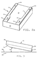
- a magnetic head slider 10 is formed with two side rails 12 and 14.
- the inner sides of the two rails border on a recessed section 18 that is formed by etching, ion milling, or some other machining technique.
- the recessed section 18, which is open at both ends extends from the leading end 20 of the slider to the trailing end 22 of the slider.
- Magnetic transducers 24, preferably of the thin film type, are bonded at the trailing ends of the rails 12 and 14 with their transducing gaps flush with the rail surface.
- the side rails 12 and 14 have a chamfered or tapered height section 16 at the leading end 20 and a width that decreases from the leading end to a point remote from the leading end. In the embodiment of the invention shown in FIG. 1, the side rails 12 and 14 are widest at the leading end 20 and decrease to their narrowest point at the trailing end 22 of the slider.
- each of the side rails 12 and 14 has the leading end formed as a taper section 16.
- Each of the side rails 12 and 14 includes a wide section 26 and 28 at the leading end 20 of the slider having substantially parallel sides and a width W1 followed by a flared section 30 and 32.
- Flared sections 30 and 32 extend to a break point from which they are followed by narrow sections 34 and 36 having substantially parallel sides and a width W2 that is less than the width W1.
- Narrow sections 34 and 36 extend to the trailing end 22 of the rails 12 and 14.
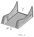
- the configuration of the slider 10 which is shown in FIGS. 1, 2a and 2b has different pressure zones as can be seen by reference to FIG. 3.
- the pressure zones are formed when the slider is positioned adjacent to a record surface 38 (FIG. 3) moving in the direction of arrow 39 to provide load forces on the slider assembly that are balanced in such a manner that the desired flying characteristics for the slider can be achieved.
- the slider has a positive pressure zone along the side rails 12 and 14, a near ambient zone in recessed section 18, and a small negative pressure zone adjacent the flared sections 30 and 32.
- the pressure components are combined so that the slider 10 flies at a desired pitch angle ⁇ (Fig. 3) relative to a moving record disk surface 38 with an attitude by which the trailing end 22 of slider 10, where the transducer 24 is mounted, is closest to the disk surface 38.
- Two of the factors which establish the pitch angle ⁇ are the ratio of the width W1 of the wide rail section 26 and 28 to the width W2 of the narrow rail section 34 and 36, and the ratio of the length L1 of the wide rail section to the overall length L of the slider.
- the ratio W1/W2 is referred to as the rail ratio
- the ratio L1/L is referred to as the length ratio
- the length of the flared sections 30 and 32 is a constant K.
- a rail ratio and a length ratio can be chosen to produce the pitch angle ⁇ desired to compensate for a forward movement of the suspension attachment, the lowering of the flying height or any other reason.
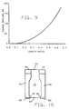
- the relief depth of the recessed section 18 Another factor which establishes the flying characteristics of the slider is the relief depth of the recessed section 18. As shown in FIG. 5, the flying height of the embodiment shown in the drawings varies significantly when the depth is small. However, for depths greater than about 15 microns, the flying height changes very little with depth, thus allowing reasonable manufacturing tolerances.
- FIG. 6 shows that, in embodiments similar to that shown in FIGS. 2a and 2b, the change in pitch angle ⁇ increases approximately linearly with increasing rail ratio for a specific length ratio. Increasing the length ratio causes the pitch to be more sensitive to rail ratio.
- FIG. 7 shows a plot for sliders having the same length ratio as FIG. 6, and FIG. 7 shows that the change in spacing goes down for rail ratios over about 1.2 for the length ratio plotted. As the length ratio is increased, the curve tends to flatten and eventually goes positive.
- FIG. 8 shows that the change in pitch angle ⁇ increases to a length ratio of about 0.4 and then begins to decrease for the value of rail ratio plotted. Increasing the rail ratio causes increased sensitivity of the length ratio to changes in flying height.
- FIG. 7 shows a plot for sliders having the same length ratio as FIG. 6, and FIG. 7 shows that the change in spacing goes down for rail ratios over about 1.2 for the length ratio plotted. As the length ratio is increased, the curve tends to flatten and eventually goes positive.
- FIG. 10 Another embodiment of the invention is shown in FIG. 10.
- the magnetic transducer may need to have a greater area than that provided by the rails in the FIGS. 1, 2a and 2b embodiment.
- the trailing end of the rails 42 and 44 is provided with a flared-out section 46 and 48. Since the flared section 46 and 48 produces only a slight change in the positive pressure at the trailing end of the rails, no significant effect on flying attitude of the slider is produced.
- Suitable contours can also be used for both the inner and outer sides of the side rails to obtain the desired flying characteristics for the slider, and these contours are characterised by a width that is wide at the leading end and decreases to a point near to the trailing end of the slider.
Landscapes
- Adjustment Of The Magnetic Head Position Track Following On Tapes (AREA)
- Magnetic Heads (AREA)
Claims (3)
- Patin à coussin d'air pour supporter un transducteur (24,40) par rapport à un milieu d'enregistrement en mouvement, la face inférieure du patin étant formée pour définir deux rails latéraux correspondants mutuellement espacés (12,14,42,44) de sorte qu'il y a une partie évidée (18) ouverte aux deux extrémités et s'étendant de l'extrémité de tête (20) du patin à son extrémité de queue (22), chacun des rails latéraux étant chanfreiné (16) à son extrémité de tête et comportant une région de tête, une région intermédiaire et une région de queue, la région de tête étant plus large que la région intermédiaire et la région de queue sensiblement sur la totalité de leurs longueurs respectives, lesdites régions de tête et de queue ayant une largeur sensiblement constante et ladite région intermédiaire devenant progressivement plus étroite jusqu'à un point de transition, et les rails latéraux et la partie évidée engendrant un profil de pression combiné lorsque le patin est placé près d'un milieu d'enregistrement en mouvement, de sorte que le patin prend une orientation, ayant un angle d'inclinaison prédéterminé par rapport au milieu d'enregistrement en mouvement, dans laquelle l'espacement minimal entre le patin et le milieu d'enregistrement se trouve à l'extrémité de queue (22) du patin.
- Assemblage comprenant un patin suivant la revendication 1 et une tête de transduction magnétique individuelle (24,40) supportée sur le bord de queue (22) de chacun des rails latéraux.
- Patin à coussin d'air suivant la revendication 2, dans lequel la région de queue de chacun des rails (42,44) s'évase vers l'extérieur, au bord de queue, afin de procurer une plus grande surface de montage pour ledit transducteur individuel (40), la partie évasée (46,48) étant suffisamment petite pour ne pas affecter sensiblement ledit angle d'inclinaison prédéterminé et ledit espacement minimal (figure 10).
Applications Claiming Priority (2)
| Application Number | Priority Date | Filing Date | Title |
|---|---|---|---|
| US841646 | 1986-03-20 | ||
| US06/841,646 US4734803A (en) | 1986-03-20 | 1986-03-20 | Magnetic head air bearing slider |
Publications (2)
| Publication Number | Publication Date |
|---|---|
| EP0237752A1 EP0237752A1 (fr) | 1987-09-23 |
| EP0237752B1 true EP0237752B1 (fr) | 1991-10-16 |
Family
ID=25285370
Family Applications (1)
| Application Number | Title | Priority Date | Filing Date |
|---|---|---|---|
| EP87101588A Expired - Lifetime EP0237752B1 (fr) | 1986-03-20 | 1987-02-05 | Patin flottant sur coussin d'air |
Country Status (4)
| Country | Link |
|---|---|
| US (1) | US4734803A (fr) |
| EP (1) | EP0237752B1 (fr) |
| JP (1) | JP2689373B2 (fr) |
| DE (1) | DE3773711D1 (fr) |
Families Citing this family (44)
| Publication number | Priority date | Publication date | Assignee | Title |
|---|---|---|---|---|
| DE3779641T2 (de) * | 1987-09-22 | 1993-02-04 | Ibm Deutschland | Form einer gleitschuhschiene und ihr mechanisches herstellungsverfahren. |
| JP2668708B2 (ja) * | 1988-06-20 | 1997-10-27 | 株式会社日立製作所 | 浮動ヘッドスライダ |
| US4894740A (en) * | 1988-09-28 | 1990-01-16 | International Business Machines Corporation | Magnetic head air bearing slider |
| US5251083A (en) * | 1989-05-29 | 1993-10-05 | Hitachi, Ltd. | Flying head slider and method of producing the same |
| JP2765952B2 (ja) * | 1989-05-29 | 1998-06-18 | 株式会社日立製作所 | 浮動ヘツドスライダ |
| US5021906A (en) * | 1989-10-31 | 1991-06-04 | International Business Machines Corporation | Programmable air bearing slider including magnetic read/write element |
| JPH03183075A (ja) * | 1989-12-11 | 1991-08-09 | Sony Corp | ヘッドスライダ装置 |
| JP2596171B2 (ja) * | 1990-04-24 | 1997-04-02 | 富士通株式会社 | 磁気ディスク装置 |
| US5062017A (en) * | 1990-05-25 | 1991-10-29 | Seagate Technology, Inc. | Hour-glass disk head slider |
| US5218494A (en) * | 1990-05-25 | 1993-06-08 | Seagate Technology, Inc. | Negative pressure air bearing slider having isolation channels with edge step |
| US5343343A (en) * | 1990-05-25 | 1994-08-30 | Seagate Technology, Inc. | Air bearing slider with relieved rail ends |
| US5274518A (en) * | 1990-05-25 | 1993-12-28 | Seagate Technology, Inc. | Negative pressure air bearing slider having converging isolation channels |
| US5196973A (en) * | 1990-05-25 | 1993-03-23 | Seagate Technology, Inc. | Negative pressure air bearing slider having isolation channels which terminate prior to trailing edge |
| US5128822A (en) * | 1990-05-25 | 1992-07-07 | Seagate Technology, Inc. | Configuration for negative pressure air bearing sliders |
| JPH04228157A (ja) * | 1990-07-13 | 1992-08-18 | Fujitsu Ltd | 磁気ヘッドスライダ |
| US5086360A (en) * | 1990-09-06 | 1992-02-04 | Applied Magnetics Corporation | Constant flying height slider |
| US5267109A (en) * | 1991-06-14 | 1993-11-30 | Seagate Technology, Inc. | Air bearing slider with relieved trailing edge |
| US5287235A (en) * | 1991-10-28 | 1994-02-15 | International Business Machines Corporation | Slider air bearing surface with angled rail configuration |
| JPH0643821U (ja) * | 1992-10-29 | 1994-06-10 | ミツミ電機株式会社 | 磁気ヘッド |
| US5404256A (en) * | 1992-12-07 | 1995-04-04 | White; James W. | Transverse and negative pressure contour gas bearing slider |
| US5726831A (en) * | 1992-12-07 | 1998-03-10 | White; James W. | Methods for operating a gas bearing slider |
| JPH0721717A (ja) * | 1993-06-24 | 1995-01-24 | Internatl Business Mach Corp <Ibm> | 速度および斜行依存性のないエア・ベアリング・スライダ |
| US5654853A (en) * | 1994-02-04 | 1997-08-05 | Seagate Technology, Inc. | Disc storage device having a magnetic head air bearing slider configuration for reduced disc overhead |
| KR0175255B1 (ko) * | 1994-07-07 | 1999-04-15 | 김광호 | 하드디스크 드라이브의 자기기록용 헤드 |
| AU2970395A (en) * | 1994-07-18 | 1996-02-16 | Sunward Technologies, Inc. | Contact recording slider with active contact surfaces |
| JP3642821B2 (ja) * | 1995-03-17 | 2005-04-27 | 富士通株式会社 | 磁気ヘッドスライダ |
| US5724212A (en) * | 1995-05-26 | 1998-03-03 | Quantum Corporation | Method and apparatus for increasing data density in magnetic data storage disk drives |
| US5831791A (en) * | 1996-03-27 | 1998-11-03 | Headway Technologies, Inc. | Negative Pressure air bearing slider having transition region between positive and negative pressure regions |
| JP2001508579A (ja) * | 1997-01-15 | 2001-06-26 | シーゲイト テクノロジー エルエルシー | 後縁カットで終了するサイド・レールを有するスライダー |
| JP3292296B2 (ja) * | 1997-03-25 | 2002-06-17 | ティーディーケイ株式会社 | スライダ、ヘッド、ヘッド装置及び記録再生装置 |
| USD475716S1 (en) | 1997-03-25 | 2003-06-10 | Tdk Corporation | Combined slider and head for reading or writing information on a disk |
| US6611401B1 (en) | 1997-04-02 | 2003-08-26 | Marburg Technology, Inc. | Glide head with a transverse contact rail |
| US5963396A (en) | 1997-04-02 | 1999-10-05 | Marburg Technology, Inc. | Glide head with an outside active rail |
| JP3237751B2 (ja) * | 1997-04-11 | 2001-12-10 | ティーディーケイ株式会社 | 磁気ヘッド |
| US5986850A (en) * | 1997-06-16 | 1999-11-16 | Seagate Technology, Inc. | Positive pressure optical slider having wide center rail |
| WO1999005679A1 (fr) | 1997-07-23 | 1999-02-04 | Seagate Technology, Inc. | Curseur optique a pression positive avec plages de connexion laterales a extremite arriere |
| JPH11224454A (ja) | 1998-02-04 | 1999-08-17 | Mitsumi Electric Co Ltd | 磁気ヘッド及びその支持構造 |
| JPH11353773A (ja) | 1998-06-11 | 1999-12-24 | Mitsumi Electric Co Ltd | 磁気ヘッド |
| US7154709B2 (en) | 2000-04-12 | 2006-12-26 | Seagate Technology Llc | Slider with recessed pressurization surfaces |
| US6700727B1 (en) | 2000-04-14 | 2004-03-02 | Seagate Technology Llc | Slider and method for actively controlling crown curvature |
| US6624984B2 (en) | 2000-05-25 | 2003-09-23 | Seagate Technology Llc | Fly height control slider with crown and cross curve de-coupling |
| SG107115A1 (en) * | 2001-10-02 | 2004-11-29 | Matsushita Electric Industrial Co Ltd | Head slider and head supporting device and disk drive |
| GB0502677D0 (en) * | 2005-02-09 | 2005-03-16 | Taylor Hobson Ltd | Apparatus for and a method of determining a surface characteristic |
| US8248729B2 (en) * | 2006-11-16 | 2012-08-21 | Hitachi Global Storage Technologies, Netherlands B.V. | Slider with hook-shaped air compression mechanisms near trailing edge corners |
Family Cites Families (12)
| Publication number | Priority date | Publication date | Assignee | Title |
|---|---|---|---|---|
| US3823416A (en) * | 1973-03-01 | 1974-07-09 | Ibm | Flying magnetic transducer assembly having three rails |
| FR2408897A1 (fr) * | 1977-11-15 | 1979-06-08 | Cii Honeywell Bull | Procede du temps de decollage d'une plate-forme comportant au moins un transducteur de lecture/ecriture d'un support d'information, plate-forme resultant de l'execution du procede, et procede de fabrication d'une telle plate-forme |
| US4214287A (en) * | 1978-07-20 | 1980-07-22 | Burroughs Corporation | Novel TSF head pair for dual recording on flexible disks |
| JPS55118373U (fr) * | 1979-02-15 | 1980-08-21 | ||
| JPS56134354A (en) * | 1980-03-24 | 1981-10-21 | Hitachi Ltd | Floating type magnetic head |
| EP0076361B1 (fr) * | 1981-10-07 | 1986-01-29 | International Business Machines Corporation | Patin flottant sur coussin d'air pour un transducteur |
| US4475135A (en) * | 1981-10-07 | 1984-10-02 | International Business Machines | Magnetic head air bearing slider |
| US4555739A (en) * | 1982-11-26 | 1985-11-26 | International Business Machines Corporation | Semi self-loading ferrite head |
| CA1215778A (fr) * | 1983-05-19 | 1986-12-23 | James K. Knudsen | Ensemble transducteur-curseur a surfaces de rails de suspension a air arrondies |
| DE3376036D1 (en) * | 1983-08-17 | 1988-04-21 | Ibm Deutschland | Method of manufacturing a magnetic head flying body |
| JPS60101781A (ja) * | 1983-11-07 | 1985-06-05 | Fujitsu Ltd | 磁気ヘツド用スライダ |
| JPS6116765U (ja) * | 1984-06-29 | 1986-01-31 | アルプス電気株式会社 | 浮動式磁気ヘツド |
-
1986
- 1986-03-20 US US06/841,646 patent/US4734803A/en not_active Expired - Lifetime
-
1987
- 1987-02-05 DE DE8787101588T patent/DE3773711D1/de not_active Expired - Lifetime
- 1987-02-05 EP EP87101588A patent/EP0237752B1/fr not_active Expired - Lifetime
- 1987-02-20 JP JP62035959A patent/JP2689373B2/ja not_active Expired - Lifetime
Also Published As
| Publication number | Publication date |
|---|---|
| JPS62231481A (ja) | 1987-10-12 |
| US4734803A (en) | 1988-03-29 |
| JP2689373B2 (ja) | 1997-12-10 |
| DE3773711D1 (de) | 1991-11-21 |
| EP0237752A1 (fr) | 1987-09-23 |
Similar Documents
| Publication | Publication Date | Title |
|---|---|---|
| EP0237752B1 (fr) | Patin flottant sur coussin d'air | |
| CA1311838C (fr) | Curseur a coussin d'air pour tete magnetique | |
| US3855625A (en) | Magnetic head slider assembly | |
| US5396386A (en) | Roll insensitive air bearing slider | |
| KR0145029B1 (ko) | 자기 기록 디스크 드라이브 및 변환기 조립체 | |
| US6229672B1 (en) | High gram load air bearing geometry for a tripad slider | |
| EP0458444B1 (fr) | Patin de tête sur coussin d'air pour disque | |
| US5359480A (en) | Magnetic head air bearing slider | |
| US5650893A (en) | Roll insensitive air bearing slider | |
| US5568981A (en) | Negative pressure air bearing slider | |
| US7515384B2 (en) | Method and apparatus for providing a three stepped air bearing having a funnel structure for controlling air flow to improve fly height performance | |
| US6128163A (en) | Disk drive including slider with recessed magneto-resistive transducer | |
| IE970591A1 (en) | A slider and method for making same | |
| JP3207269B2 (ja) | 磁気記録用フライトスライダー | |
| US5128821A (en) | Flying head slider and magnetic disk unit employing same | |
| US7038883B2 (en) | Magnetic head slider, support therefor and magnetic disk unit | |
| US6125005A (en) | Altitude insensitive air bearing using pitch compensation for data storage application | |
| US5685645A (en) | Roll balance sub-ambient pressure air bearing slider | |
| US5704715A (en) | Altitude insensitive air bearing slider | |
| US5889637A (en) | Air bearing magnetic head slider | |
| US5825588A (en) | Roll insensitive air bearing slider | |
| US4769727A (en) | Self-loading magnetic head slider | |
| JPH0417176A (ja) | 浮動ヘッドスライダ | |
| US5251083A (en) | Flying head slider and method of producing the same | |
| US7251107B2 (en) | Method and apparatus for providing an air bearing pad having improved roll angle sigma |
Legal Events
| Date | Code | Title | Description |
|---|---|---|---|
| PUAI | Public reference made under article 153(3) epc to a published international application that has entered the european phase |
Free format text: ORIGINAL CODE: 0009012 |
|
| AK | Designated contracting states |
Kind code of ref document: A1 Designated state(s): DE FR GB |
|
| 17P | Request for examination filed |
Effective date: 19880126 |
|
| 17Q | First examination report despatched |
Effective date: 19890919 |
|
| GRAA | (expected) grant |
Free format text: ORIGINAL CODE: 0009210 |
|
| AK | Designated contracting states |
Kind code of ref document: B1 Designated state(s): DE FR GB |
|
| REF | Corresponds to: |
Ref document number: 3773711 Country of ref document: DE Date of ref document: 19911121 |
|
| ET | Fr: translation filed | ||
| PLBE | No opposition filed within time limit |
Free format text: ORIGINAL CODE: 0009261 |
|
| STAA | Information on the status of an ep patent application or granted ep patent |
Free format text: STATUS: NO OPPOSITION FILED WITHIN TIME LIMIT |
|
| 26N | No opposition filed | ||
| REG | Reference to a national code |
Ref country code: GB Ref legal event code: IF02 |
|
| REG | Reference to a national code |
Ref country code: FR Ref legal event code: TP |
|
| REG | Reference to a national code |
Ref country code: GB Ref legal event code: 732E |
|
| PGFP | Annual fee paid to national office [announced via postgrant information from national office to epo] |
Ref country code: FR Payment date: 20060224 Year of fee payment: 20 |
|
| PGFP | Annual fee paid to national office [announced via postgrant information from national office to epo] |
Ref country code: GB Payment date: 20060227 Year of fee payment: 20 |
|
| PGFP | Annual fee paid to national office [announced via postgrant information from national office to epo] |
Ref country code: DE Payment date: 20060309 Year of fee payment: 20 |
|
| PG25 | Lapsed in a contracting state [announced via postgrant information from national office to epo] |
Ref country code: GB Free format text: LAPSE BECAUSE OF EXPIRATION OF PROTECTION Effective date: 20070204 |
|
| REG | Reference to a national code |
Ref country code: GB Ref legal event code: PE20 |