EP0238917A1 - A device provided with means for fixing it to a support wall - Google Patents
A device provided with means for fixing it to a support wall Download PDFInfo
- Publication number
- EP0238917A1 EP0238917A1 EP87103253A EP87103253A EP0238917A1 EP 0238917 A1 EP0238917 A1 EP 0238917A1 EP 87103253 A EP87103253 A EP 87103253A EP 87103253 A EP87103253 A EP 87103253A EP 0238917 A1 EP0238917 A1 EP 0238917A1
- Authority
- EP
- European Patent Office
- Prior art keywords
- fact
- nail
- essentially
- wall
- slidable
- Prior art date
- Legal status (The legal status is an assumption and is not a legal conclusion. Google has not performed a legal analysis and makes no representation as to the accuracy of the status listed.)
- Withdrawn
Links
- 239000002360 explosive Substances 0.000 claims abstract description 11
- 239000007789 gas Substances 0.000 claims abstract description 10
- 239000000463 material Substances 0.000 claims description 8
- 238000006073 displacement reaction Methods 0.000 claims description 5
- 229920003023 plastic Polymers 0.000 claims description 2
- 239000004033 plastic Substances 0.000 claims description 2
- 238000007789 sealing Methods 0.000 claims 3
- 230000008878 coupling Effects 0.000 claims 2
- 238000010168 coupling process Methods 0.000 claims 2
- 238000005859 coupling reaction Methods 0.000 claims 2
- 238000010304 firing Methods 0.000 claims 2
- 238000004891 communication Methods 0.000 claims 1
- 239000002184 metal Substances 0.000 description 2
- 241000252254 Catostomidae Species 0.000 description 1
- 229910000831 Steel Inorganic materials 0.000 description 1
- 230000004913 activation Effects 0.000 description 1
- 238000004873 anchoring Methods 0.000 description 1
- 239000002131 composite material Substances 0.000 description 1
- 230000000694 effects Effects 0.000 description 1
- 229910001234 light alloy Inorganic materials 0.000 description 1
- 230000014759 maintenance of location Effects 0.000 description 1
- 239000011150 reinforced concrete Substances 0.000 description 1
- 230000000717 retained effect Effects 0.000 description 1
- 235000015170 shellfish Nutrition 0.000 description 1
- 239000010959 steel Substances 0.000 description 1
- 210000002105 tongue Anatomy 0.000 description 1
Images
Classifications
-
- B—PERFORMING OPERATIONS; TRANSPORTING
- B25—HAND TOOLS; PORTABLE POWER-DRIVEN TOOLS; MANIPULATORS
- B25C—HAND-HELD NAILING OR STAPLING TOOLS; MANUALLY OPERATED PORTABLE STAPLING TOOLS
- B25C1/00—Hand-held nailing tools; Nail feeding devices
- B25C1/08—Hand-held nailing tools; Nail feeding devices operated by combustion pressure
- B25C1/10—Hand-held nailing tools; Nail feeding devices operated by combustion pressure generated by detonation of a cartridge
- B25C1/12—Hand-held nailing tools; Nail feeding devices operated by combustion pressure generated by detonation of a cartridge acting directly on the bolt
-
- B—PERFORMING OPERATIONS; TRANSPORTING
- B25—HAND TOOLS; PORTABLE POWER-DRIVEN TOOLS; MANIPULATORS
- B25C—HAND-HELD NAILING OR STAPLING TOOLS; MANUALLY OPERATED PORTABLE STAPLING TOOLS
- B25C1/00—Hand-held nailing tools; Nail feeding devices
- B25C1/08—Hand-held nailing tools; Nail feeding devices operated by combustion pressure
- B25C1/10—Hand-held nailing tools; Nail feeding devices operated by combustion pressure generated by detonation of a cartridge
- B25C1/18—Details and accessories, e.g. splinter guards, spall minimisers
- B25C1/188—Arrangements at the forward end of the barrel, e.g. splinter guards, spall minimisers, safety arrangements, silencers, bolt retainers
-
- F—MECHANICAL ENGINEERING; LIGHTING; HEATING; WEAPONS; BLASTING
- F42—AMMUNITION; BLASTING
- F42B—EXPLOSIVE CHARGES, e.g. FOR BLASTING, FIREWORKS, AMMUNITION
- F42B22/00—Marine mines, e.g. launched by surface vessels or submarines
-
- F—MECHANICAL ENGINEERING; LIGHTING; HEATING; WEAPONS; BLASTING
- F42—AMMUNITION; BLASTING
- F42B—EXPLOSIVE CHARGES, e.g. FOR BLASTING, FIREWORKS, AMMUNITION
- F42B3/00—Blasting cartridges, i.e. case and explosive
- F42B3/006—Explosive bolts; Explosive actuators
Definitions
- the present invention relates to a device provided with means for fixing it to a support wall.
- the device according to the present invention has the purpose of anchoring itself as well as an object connected to it, such as for example an explosive charge, to a wall of a ship or a submerged structure with the maximum possible discretion.
- an explosive charge to the hull of a ship is effected by means of the use of suitable suction or magnetic systems; the effectiveness of the fixing in this case is not, however, reliable, especially when the surface of the hull is not smooth but has encrustations of various type due for example to the presence of shellfish, or else the fixing cannot be made in that the hull is made of a material other than steel such as light alloy or composite material.
- the object of the present invention is that of providing a device which can fix itself to a support wall of a structure, preferably a submerged structure, and which is able to effect a secure mechanical connection with the maximum containment of noise or other signals which become manifest during the fixing operations.
- the said object is achieved with the present invention in that it relates to a fixing device for mechanically connecting itself to a support wall of appropriate material, characterised by the fact that it includes a nail provided with a head and a shank, which can be thrust towards the said wall by the action exerted by gases developed by an explosive cartridge; the said device further including braking means operable, by deforming, to absorb a part of the kinetic energy associated in use with the said nail, in such a way as to retain this latter in a predetermined position in which the head and an adjacent part of the shank are rigidly connected to the body of the said device whilst an end part of the shank projects from the body of the said device to be driven into the said wall without the escape of gases and therefore without noise.
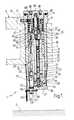
- the reference numeral 1 generally indicates a device which can be fixed to a support wall 2, such as, for example, the outer wall of a ship or a submerged structure in general.
- the device 1 has a hollow body 3 of essentially cylindrical structure, which is mechanically coupled with a cylindrical seat 4 formed in a handle 5 which, in a manner not illustrated, extends from the body of an explosive charge also to be fixed to the said wall 2.
- the body 3 of the device 1 has a head portion 6 of enlarged section which rests on the upper surface of the handle 5, an intermediate portion 7 which is received within the interior of the cylindrical seat 4,and an end portion 8 which extends beyond the handle 5 on the side opposite the head portion 6.
- the portion 8 is coupled to the handle 5 by means of an annular band 9 fitted around the portion 8 itself, and from which extend a plurality of elastically deformable tongues 10 facing outwardly in the direction of the head portion 6, in such a way as to interfere with the facing surface of the handle 5.
- a reference peg 11 extending radially and able to cooperate with a radial seat 12 in the handle 5 for the purpose of ensuring correct relative positioning of the body 3 of the device 1 with respect to the said handle 5.
- the device 1 essentially comprises a nail 15 provided with a head 16 and a shank 17, which can be thrust in the direction of the wall 2 by the action exerted by the gases developed by an explosive cartridge 18.
- the nail 15 and the cartridge 18 are housed within a cylindrical bore 19 of a barrel 20 and between them there is interposed a seal 21 in the form of a flat disc which is slidable along the barrel 20 and which has the purpose of preventing gases developed by the cartridge 18 from being able to escape past the head 16 of the nail 15 and therefore reduce the effectiveness of the thrust transmitted to the nail itself.
- the tip of this latter is covered by a cap 22, conveniently made of a plastics material, the purpose of which is that of maintaining the nail 15 correctly positioned with respect to.the bore 19 of the barrel 20.
- the device 1 further includes a bush 25, close to an outlet opening 24 of the barrel 20, which rests by means of a metal disc 26 on a bottom wall 27 of the body 3 of the device 1.
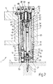
- the bush 25 is made of plastically deformable material and, between it and the facing surface of the end portion 8 of the body 3 there is provided an expansion chamber 28 which, in use, is partially occupied by the bush 25 deformed essentially by the head 16 of the nail 15 (see also Figure 2).
- the object of the bush 25 is therefore that of absorbing, by deformation, a part of the kinetic energy associated in use with the nail 15 in such a way as to retain this latter in a predetermined position in which the head 16 and a part of the shank 17 adjacent to it are rigidly connected to the body 3 of the device 1, whilst an end part of the shank 17 projects from the body 3, after having pierced the disc 26 and the bottom wall 27, to drive itself into the said support wall 2.
- the barrel 20 is housed within a cylindrical seat 30 presented by the body 3 and defining with this latter a chamber 31 communicating with the internal cylindrical bore of the barrel 20 through a plurality of radial through holes 32 of the barrel 20, essentially at its outlet opening 24.
- a tubular shutter 34 within which a striker 35 is axially slidable against the action of a coil spring 36; in more detail, the opposite ends of the coil spring 36 cooperate, respectively, with a radial annular projection 37 of the striker 35 and a stop portion 38 of a plug 39 which sealingly closes the top of the body 3 with the interposition of an annular seal 40.
- the projection 37 of the striker 35 has, on the side facing the barrel 20, a frustoconical surface 42 which cooperates with at least one ball 43 partially housed within an associated radial recess 44 in the shutter 34.
- a sleeve 46 is axially slidable against the resilient action exerted by a coil spring 47 the opposite end portions of which rest respectively on the sleeve 46 itself and on a surface 48 of the plug 39.
- the sleeve 46 On the side facing the shutter 34 the sleeve 46 has an annular seat 49 with an essentially hemispherical transverse section which, in the course of the said longitudinal sliding, can line up with the radial recess 44 to receive the ball 43.
- the axial displacement of the sleeve 46 is controlled by a small piston 51 the axis of which is parallel to the axis of the barrel 20 and which has a threaded end 52 which engages a corresponding threaded hole in the sleeve 46, and an opposite end 53 which projects from the body 3 of the device 1 through the said bottom wall 27.
- the small piston 51 has a portion 54 of reduced section around which is disposed a toroidal seal 55.
- the end portion 53 of the small piston 51 further has a radial through hole 57 which is engaged by a cotter pin 58 carrying at one end a ring 59 and defining with this latter a safety mechanism 60 tending to prevent the accidental and unwanted displacement of the small piston 51.
- the device 1 operates as follows. It is first of all observed that in Figure 1 the device 1 is illustrated in the safety position. In fact, by reason of the cotter pin 58 of the mechanism 60 the piston 51 cannot move upwardly to carry the seat 49 of the sleeve 46 into correspondence with the ball 43. This latter therefore prevents the downward movement of the striker 35.
- the gases developed by the cartridge 18 cause expulsion of the nail 15 the tip of which traverses the bush 25, pierces the metal disc 26 and the bottom wall 27 of the body 3, driving itself into the wall 2.
- the gases developed by the cartridge 18 can also flow out into the interior of the chamber 31 so that the pressure exerted by these latter on the head 16 of the nail 15 falls rapidly.
- the head 16 of this nail deforms part of the bush 25 which is dimensioned in such a way as to retain the said head 16-as well as a portion of the shank 17 adjacent to it. In this way the nail 15 performs the function of a mechanical connection element between the device 1 and the facing wall 2.
- the correct fixing of the device 1 to the wall 2 is guaranteed by the fact that the activation of the cartridge 18 takes place only when the end 53 of the piston 51 is thrust upwardly by the wall 2 itself and has performed the required translation.
- the device 1 described above can be modified and varied without by this departing from the present invention.
- the use of the device 1 to fix an explosive charge to the wall of the hull of a ship must not be considered as limitative: in fact, this device could advantageously be utilised to fix the explosive charge at the base of columns made of reinforced concrete or, indeed, to fix any object to a wall of suitable material.
Landscapes
- Engineering & Computer Science (AREA)
- General Engineering & Computer Science (AREA)
- Chemical & Material Sciences (AREA)
- Combustion & Propulsion (AREA)
- Mechanical Engineering (AREA)
- Portable Nailing Machines And Staplers (AREA)
Applications Claiming Priority (2)
| Application Number | Priority Date | Filing Date | Title |
|---|---|---|---|
| IT6723586 | 1986-03-25 | ||
| IT67235/86A IT1189628B (it) | 1986-03-25 | 1986-03-25 | Dispositivo dotato di mezzi di ancoraggio ad una parete di sopporto |
Publications (1)
| Publication Number | Publication Date |
|---|---|
| EP0238917A1 true EP0238917A1 (en) | 1987-09-30 |
Family
ID=11300714
Family Applications (1)
| Application Number | Title | Priority Date | Filing Date |
|---|---|---|---|
| EP87103253A Withdrawn EP0238917A1 (en) | 1986-03-25 | 1987-03-06 | A device provided with means for fixing it to a support wall |
Country Status (3)
| Country | Link |
|---|---|
| EP (1) | EP0238917A1 (it) |
| IL (1) | IL81980A0 (it) |
| IT (1) | IT1189628B (it) |
Cited By (2)
| Publication number | Priority date | Publication date | Assignee | Title |
|---|---|---|---|---|
| EP0330958A1 (de) * | 1988-03-03 | 1989-09-06 | HILTI Aktiengesellschaft | Pulverkraftbetriebenes Bolzensetzgerät |
| NO20190225A1 (en) * | 2019-02-19 | 2020-08-20 | Blue Logic As | A barrel unit, a charging unit, a device, a system and a method for forcing a fastening element into a structure submerged in water |
Citations (3)
| Publication number | Priority date | Publication date | Assignee | Title |
|---|---|---|---|---|
| DE1503034A1 (de) * | 1965-09-18 | 1969-10-30 | Rheinmetall Gmbh | Vorrichtung an Bolzensetzgeraeten |
| US3565312A (en) * | 1967-06-29 | 1971-02-23 | Mine Safety Appliances Co | Explosively driven stud unit |
| US4060188A (en) * | 1973-06-04 | 1977-11-29 | Aai Corporation | Impact nailing arrangement |
-
1986
- 1986-03-25 IT IT67235/86A patent/IT1189628B/it active
-
1987
- 1987-03-06 EP EP87103253A patent/EP0238917A1/en not_active Withdrawn
- 1987-03-24 IL IL81980A patent/IL81980A0/xx unknown
Patent Citations (3)
| Publication number | Priority date | Publication date | Assignee | Title |
|---|---|---|---|---|
| DE1503034A1 (de) * | 1965-09-18 | 1969-10-30 | Rheinmetall Gmbh | Vorrichtung an Bolzensetzgeraeten |
| US3565312A (en) * | 1967-06-29 | 1971-02-23 | Mine Safety Appliances Co | Explosively driven stud unit |
| US4060188A (en) * | 1973-06-04 | 1977-11-29 | Aai Corporation | Impact nailing arrangement |
Cited By (3)
| Publication number | Priority date | Publication date | Assignee | Title |
|---|---|---|---|---|
| EP0330958A1 (de) * | 1988-03-03 | 1989-09-06 | HILTI Aktiengesellschaft | Pulverkraftbetriebenes Bolzensetzgerät |
| NO20190225A1 (en) * | 2019-02-19 | 2020-08-20 | Blue Logic As | A barrel unit, a charging unit, a device, a system and a method for forcing a fastening element into a structure submerged in water |
| NO345425B1 (en) * | 2019-02-19 | 2021-01-25 | Blue Logic As | A barrel unit, a charging unit, a device, a system and a method for forcing a fastening element into a structure submerged in water |
Also Published As
| Publication number | Publication date |
|---|---|
| IL81980A0 (en) | 1987-10-20 |
| IT8667235A1 (it) | 1987-09-25 |
| IT8667235A0 (it) | 1986-03-25 |
| IT1189628B (it) | 1988-02-04 |
Similar Documents
| Publication | Publication Date | Title |
|---|---|---|
| US4824003A (en) | Indirect firing fastener driving tool | |
| US5671650A (en) | Slotted nut type releasing device for a microsatellite, with full mechanical and pyrotechnical redundancy | |
| US6129236A (en) | Tank for the liquid storage and expulsion | |
| US6123242A (en) | Explosive powder charge operated bolt-setting tool | |
| US5207196A (en) | Pre-assembled unit for engine valve system | |
| US6336641B1 (en) | Break-away muzzle cap retention mechanism | |
| US5115708A (en) | Device for temporary mechanical attachment of an object to a support and rapid ejection of the object from the support | |
| IE46343B1 (en) | Improvements in or relating to the tapping of gas from a cartridge | |
| RU95118416A (ru) | Клапан для противопожарной установки | |
| US4031840A (en) | Process and apparatus for recovering sunken wrecks | |
| US5413281A (en) | Fuel injection nozzle for an internal combustion engine | |
| US2465009A (en) | Concussion detonator | |
| US6085958A (en) | Explosive powder charge operated bolt-setting tool | |
| US3577949A (en) | Explosively propelled underwater embedment anchor assembly | |
| US5102047A (en) | Fuel injection pump for internal combustion engines | |
| US3032000A (en) | Embedment anchor | |
| US4915618A (en) | Igniter for thermal lance | |
| GB1174049A (en) | Rocket Launcher Device | |
| US4060188A (en) | Impact nailing arrangement | |
| US5395149A (en) | Device for holding an object onto a support and subsequently separating it therefrom in a controlled sequence | |
| US3839984A (en) | Safe and arm mechanism for an embedment anchor propellant | |
| US4458598A (en) | Assembly formed by a projectile and the means for launching this projectile | |
| US4333595A (en) | Offset piston for powder actuated tools | |
| JP3636375B2 (ja) | 内燃機関の燃料噴射装置の搬送ポンプのための手動操作可能なポンプ | |
| KR870002027B1 (ko) | 지뢰용 점화장치 |
Legal Events
| Date | Code | Title | Description |
|---|---|---|---|
| PUAI | Public reference made under article 153(3) epc to a published international application that has entered the european phase |
Free format text: ORIGINAL CODE: 0009012 |
|
| AK | Designated contracting states |
Kind code of ref document: A1 Designated state(s): AT BE DE ES FR GB GR SE |
|
| STAA | Information on the status of an ep patent application or granted ep patent |
Free format text: STATUS: THE APPLICATION IS DEEMED TO BE WITHDRAWN |
|
| 18D | Application deemed to be withdrawn |
Effective date: 19880331 |
|
| RIN1 | Information on inventor provided before grant (corrected) |
Inventor name: TOPA, FERDINANDO |