EP0239402A2 - Manchon de connexion de câbles - Google Patents
Manchon de connexion de câbles Download PDFInfo
- Publication number
- EP0239402A2 EP0239402A2 EP87302630A EP87302630A EP0239402A2 EP 0239402 A2 EP0239402 A2 EP 0239402A2 EP 87302630 A EP87302630 A EP 87302630A EP 87302630 A EP87302630 A EP 87302630A EP 0239402 A2 EP0239402 A2 EP 0239402A2
- Authority
- EP
- European Patent Office
- Prior art keywords
- tongues
- cable connection
- sheet
- longitudinal direction
- sleeve
- Prior art date
- Legal status (The legal status is an assumption and is not a legal conclusion. Google has not performed a legal analysis and makes no representation as to the accuracy of the status listed.)
- Withdrawn
Links
- 210000002105 tongue Anatomy 0.000 claims abstract description 37
- 238000005520 cutting process Methods 0.000 claims abstract description 14
- 239000000463 material Substances 0.000 claims description 7
- 239000002184 metal Substances 0.000 claims description 4
- 230000015572 biosynthetic process Effects 0.000 description 1
- 239000002131 composite material Substances 0.000 description 1
- 239000011888 foil Substances 0.000 description 1
- 238000004519 manufacturing process Methods 0.000 description 1
- 238000001465 metallisation Methods 0.000 description 1
- 239000002985 plastic film Substances 0.000 description 1
- 229920000728 polyester Polymers 0.000 description 1
- 238000005096 rolling process Methods 0.000 description 1
Images
Classifications
-
- H—ELECTRICITY
- H02—GENERATION; CONVERSION OR DISTRIBUTION OF ELECTRIC POWER
- H02G—INSTALLATION OF ELECTRIC CABLES OR LINES, OR OF COMBINED OPTICAL AND ELECTRIC CABLES OR LINES
- H02G15/00—Cable fittings
- H02G15/08—Cable junctions
- H02G15/18—Cable junctions protected by sleeves, e.g. for communication cable
-
- H—ELECTRICITY
- H02—GENERATION; CONVERSION OR DISTRIBUTION OF ELECTRIC POWER
- H02G—INSTALLATION OF ELECTRIC CABLES OR LINES, OR OF COMBINED OPTICAL AND ELECTRIC CABLES OR LINES
- H02G15/00—Cable fittings
- H02G15/08—Cable junctions
-
- H—ELECTRICITY
- H02—GENERATION; CONVERSION OR DISTRIBUTION OF ELECTRIC POWER
- H02G—INSTALLATION OF ELECTRIC CABLES OR LINES, OR OF COMBINED OPTICAL AND ELECTRIC CABLES OR LINES
- H02G15/00—Cable fittings
- H02G15/08—Cable junctions
- H02G15/18—Cable junctions protected by sleeves, e.g. for communication cable
- H02G15/1806—Heat shrinkable sleeves
-
- Y—GENERAL TAGGING OF NEW TECHNOLOGICAL DEVELOPMENTS; GENERAL TAGGING OF CROSS-SECTIONAL TECHNOLOGIES SPANNING OVER SEVERAL SECTIONS OF THE IPC; TECHNICAL SUBJECTS COVERED BY FORMER USPC CROSS-REFERENCE ART COLLECTIONS [XRACs] AND DIGESTS
- Y10—TECHNICAL SUBJECTS COVERED BY FORMER USPC
- Y10S—TECHNICAL SUBJECTS COVERED BY FORMER USPC CROSS-REFERENCE ART COLLECTIONS [XRACs] AND DIGESTS
- Y10S174/00—Electricity: conductors and insulators
- Y10S174/08—Shrinkable tubes
-
- Y—GENERAL TAGGING OF NEW TECHNOLOGICAL DEVELOPMENTS; GENERAL TAGGING OF CROSS-SECTIONAL TECHNOLOGIES SPANNING OVER SEVERAL SECTIONS OF THE IPC; TECHNICAL SUBJECTS COVERED BY FORMER USPC CROSS-REFERENCE ART COLLECTIONS [XRACs] AND DIGESTS
- Y10—TECHNICAL SUBJECTS COVERED BY FORMER USPC
- Y10T—TECHNICAL SUBJECTS COVERED BY FORMER US CLASSIFICATION
- Y10T428/00—Stock material or miscellaneous articles
- Y10T428/13—Hollow or container type article [e.g., tube, vase, etc.]
- Y10T428/1352—Polymer or resin containing [i.e., natural or synthetic]
- Y10T428/1355—Elemental metal containing [e.g., substrate, foil, film, coating, etc.]
- Y10T428/1359—Three or more layers [continuous layer]
Definitions
- the invention relates to a sleeve for enclosing a cable connection around which a insulating tape may be wrapped or a heat shrink sleeve may be shrunk to form a cable closure.
- Sleeves for enclosing a cable connection formed from a bendable sheet laid around the cable connection are frequently used to protectively surround cable connections prior to the application of insulating tape or a heat shrink sleeve to form a cable closure.
- the sheet may have a series of equally spaced longitudinal cuts in at least one marginal portion to be arranged transversely of the longitudinal direction of the cable connection, the cuts subdividing the marginal portion into tongues so that when the sheet is being laid around the cable connection to form the sleeve, the tongues can be tapered down onto a cable sheath at the end of the cable connection.
- a sleeve is disclosed in British patent No. 1,065,431.
- those with longitudinal cuts offer the advantage that the tongues overlap significantly on the tapering end portion of the cable connection and after being held in place, for example, insulating tape or a heat shrink sleeve, contribute to a high strength of the sleeve and the overall cable closure.
- insulating tape or a heat shrink sleeve contribute to a high strength of the sleeve and the overall cable closure.
- this can be facilitated by making the longitudinal cuts with a scissors or the like so that at least one longitudinal edge of each tongue is bent out of the face of the sheet.
- a sleeve for enclosing a cable connection comprising a bendable sheet adapted to be laid around the cable connection.
- the sheet has a series of equally spaced longitudinal cuts in at least one marginal portion to be arranged transversely of the longitudinal direction of the cable connection.
- the cuts subdivide the marginal portion into tongues and are formed by cutting lines which extend in a direction deviating from the longitudinal direction so that the free ends of the tongues are offset with respect to the base portions of the tongues in a direction transversely of the longitudinal direction.
- the desired overlap of the tongues will easily result when laying the sheet around the cable connection if the marginal portion of the sheet is manually clasped and the handed rotated in the offsetting direction of the tongues.
- greater strength will result from the sleeve and its fastening means, for instance a wrapping with insulating tape or a heat shrink sleeve.
- the cutting lines extend at least partly along a smooth curve and terminate in the longitudinal direction between the base portions of the tongues. Thereby, laying of the sheet around the cable connection to form the sleeve is facilitated, and the formation of highly stressed corners is avoided.
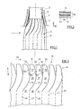
- Figure 1 shows a portion of a cable connection 1 between a cable 3 and a second cable which is not illustrated.
- a sleeve 5 is laid which was formed from an essentially rectangular flat sheet.
- the end of the sleeve 5 is fixed, for example, by a wrapping 7 of insulating tape, to the sheath 9 of the cable 3.
- An outer enclosure 11 may consist of a heat shrink sleeve shrunk down on the sleeve 5 to form the completed cable closure.
- Figure 2 shows a portion of one end of the essentially rectangular flat sheet 13 from which the sleeve 5 is made.
- the sheet 13 has, in a marginal portion 17 extending transversely of the longitudinal direction 15 of the cable connection, a series of equally spaced cutting lines 19, 21, 23 which extend generally longitudinally, and subdivide the marginal portion 17 into tongues 25, 27, 29 so that the tongues, when lead around the cable connection, as illustrated in Figure 1, can be laid with an overlap tapering down onto the cable sheath 9 at the end of the cable connection.
- the cutting lines extend in a direction deviating from the longitudinal direction 15 so that the free ends, 31, 33, 35 of the tongues are unidirectionally offset with respect to base portions 37, 39, 41 of the tongues in a direction 43 transversely of the longitudinal direction 15.
- the offsetting of the tongues 25, 27, 29 amounts to about one tongue width in the embodiment illustrated.
- the tongues will easily overlap each other when the sheet is laid around if the marginal portion 17 of the sheet 13 is manually clasped and the hand rotated in the offsetting direction 43 of the tongues.
- the cutting lines 19, 21, 23 extend smoothly and at least partly curvedly and terminate between the base portions 37, 39, 41 in the longitudinal direction 15.
- the sheet has longitudinal folding lines 45, 47, 49 which merge with the cutting lines 19, 21, 23 at the base portions 37, 39, 41 of the tongues 25, 27, 29.
- the tongues 25, 27, 29 have end portions, 51, 53, 55 or reduced width. This is obtained in the embodiment illustrated in that in the end portions 51, 53, 55, the cutting lines 19, 21, 23 are widened oppositely to the offsetting direction 43 to form cutouts 57, 59, 61.
- the other edge of the cutouts are formed by outer end portions 63, 65, 67 of the cutting lines which again extend in the longitudinal direction.
- Figure 3 shows that in the embodiment illustrated, the sheet consists of a base material 69 which is provided on one side, namely, the outer side of the sleeve 5, with a metal layer 71.
- the base material 69 of the embodiment illustrated consists of two thin layers 73, 75 which are interconnected by a connection layer 77 to form a composite sheet.
- the layers 73, 75 preferably consist of polyester.
- the metal layer 71 may be formed for instance by a vapor-deposited metallization, or a glued-on metal foil.
- the sleeve have a preferential direction of increased strength, for example by having been worked.
- This can be generated, for instance, by a rolling process, for instance in the manufacture of a plastic sheet used as the base material.
- the sheet can be easily laid around the cable connection but yet have an increased strength against deformation in a perpendicular direction.
- the strength of the sleeve and thus of the overall cable connection closure can be further increased.
- the sleeve 5 extends across the whole length of the cable connection, it is appropriately provided in a corresponding manner with cutting lines and tongues in the marginal portion (not illustrated) opposite of the marginal portion 17.
Landscapes
- Cable Accessories (AREA)
- Insulating Bodies (AREA)
Applications Claiming Priority (2)
| Application Number | Priority Date | Filing Date | Title |
|---|---|---|---|
| DE3610370A DE3610370C1 (de) | 1986-03-27 | 1986-03-27 | Einlage fuer eine Kabelverbindung |
| DE3610370 | 1986-03-27 |
Publications (2)
| Publication Number | Publication Date |
|---|---|
| EP0239402A2 true EP0239402A2 (fr) | 1987-09-30 |
| EP0239402A3 EP0239402A3 (fr) | 1989-12-20 |
Family
ID=6297404
Family Applications (1)
| Application Number | Title | Priority Date | Filing Date |
|---|---|---|---|
| EP87302630A Withdrawn EP0239402A3 (fr) | 1986-03-27 | 1987-03-26 | Manchon de connexion de câbles |
Country Status (9)
| Country | Link |
|---|---|
| US (1) | US4731271A (fr) |
| EP (1) | EP0239402A3 (fr) |
| JP (1) | JPS62234881A (fr) |
| KR (1) | KR870009510A (fr) |
| AU (1) | AU596399B2 (fr) |
| BR (1) | BR8701393A (fr) |
| DE (1) | DE3610370C1 (fr) |
| MY (1) | MY101167A (fr) |
| NZ (1) | NZ219552A (fr) |
Cited By (1)
| Publication number | Priority date | Publication date | Assignee | Title |
|---|---|---|---|---|
| US8270799B2 (en) | 2007-11-19 | 2012-09-18 | 3M Innovative Properties Company | Telecommunications cable inlet device |
Families Citing this family (10)
| Publication number | Priority date | Publication date | Assignee | Title |
|---|---|---|---|---|
| JPH0435626U (fr) * | 1990-07-24 | 1992-03-25 | ||
| DE69115708T2 (de) * | 1990-10-09 | 1996-08-08 | Raychem Corp | Wickelverschluss mit einem antioxydationsmittel gegen umwelteinflüsse für einen freiluftkabelverschluss |
| JP2641821B2 (ja) * | 1991-11-19 | 1997-08-20 | 日本電信電話株式会社 | ケーブルシール部材 |
| US5997967A (en) * | 1993-05-07 | 1999-12-07 | Hawkings; Robert Mark | Side entry device for sealing wire bundles |
| KR100567470B1 (ko) * | 1994-12-29 | 2006-06-28 | 페더럴-모굴 파워트레인 인코포레이티드 | 슬리브 제품 |
| US5613298A (en) * | 1995-01-17 | 1997-03-25 | Thomas & Betts Corporation | Forced encapsulation cable splice enclosure |
| US5802715A (en) * | 1995-01-17 | 1998-09-08 | Thomas & Betts Corporation | Method of sealing an elongate cable splice |
| US5958529A (en) * | 1996-11-20 | 1999-09-28 | Raychem Corporation | Side entry sealing device |
| JPH10336867A (ja) * | 1997-06-03 | 1998-12-18 | Japan Riicom:Kk | ケーブル接続用クロージャ |
| US10807341B2 (en) * | 2015-08-04 | 2020-10-20 | Federal-Mogul Powertrain Llc | Thermal sleeve with reflective positioning member, assembly therewith and method of construction thereof |
Family Cites Families (8)
| Publication number | Priority date | Publication date | Assignee | Title |
|---|---|---|---|---|
| GB1065431A (en) * | 1964-06-08 | 1967-04-12 | British Insulated Callenders | Improvements in or relating to electric cable joints and terminations |
| GB1431167A (en) * | 1972-09-08 | 1976-04-07 | Raychem Sa Nv | Assembly and method for protecitng and insulating a concuit junction |
| US4142592A (en) * | 1973-05-25 | 1979-03-06 | N.V. Raychem S.A. | Repairable assembly for protecting a cable junction and method of assembling same |
| DE2807154C3 (de) * | 1978-02-20 | 1985-08-01 | Walter Rose Gmbh & Co Kg, 5800 Hagen | Kabelmuffe |
| DE7930401U1 (de) * | 1979-09-11 | 1980-03-13 | N.V. Raychem S.A., Kessel-Lo (Belgien) | Kabelmuffeneinlage |
| US4426413A (en) * | 1980-06-02 | 1984-01-17 | Raychem Corporation | Heat-recoverable closure assembly |
| NZ197250A (en) * | 1980-06-02 | 1985-08-16 | Raychem Sa Nv | Recoverable sleeve and liner for covering cable joints |
| DE3439711A1 (de) * | 1984-10-30 | 1986-04-30 | Siemens AG, 1000 Berlin und 8000 München | Einlage fuer eine kabelmuffe und ein verfahren zur herstellung derselben in der kabelmuffe |
-
1986
- 1986-03-27 DE DE3610370A patent/DE3610370C1/de not_active Expired - Lifetime
-
1987
- 1987-03-02 US US07/020,565 patent/US4731271A/en not_active Expired - Fee Related
- 1987-03-04 AU AU69679/87A patent/AU596399B2/en not_active Ceased
- 1987-03-10 NZ NZ219552A patent/NZ219552A/en unknown
- 1987-03-14 MY MYPI87000295A patent/MY101167A/en unknown
- 1987-03-26 BR BR8701393A patent/BR8701393A/pt unknown
- 1987-03-26 EP EP87302630A patent/EP0239402A3/fr not_active Withdrawn
- 1987-03-26 JP JP62072971A patent/JPS62234881A/ja active Pending
- 1987-03-27 KR KR870002848A patent/KR870009510A/ko not_active Withdrawn
Cited By (1)
| Publication number | Priority date | Publication date | Assignee | Title |
|---|---|---|---|---|
| US8270799B2 (en) | 2007-11-19 | 2012-09-18 | 3M Innovative Properties Company | Telecommunications cable inlet device |
Also Published As
| Publication number | Publication date |
|---|---|
| AU596399B2 (en) | 1990-05-03 |
| NZ219552A (en) | 1990-04-26 |
| BR8701393A (pt) | 1988-01-05 |
| MY101167A (en) | 1991-07-31 |
| US4731271A (en) | 1988-03-15 |
| KR870009510A (ko) | 1987-10-27 |
| AU6967987A (en) | 1987-10-01 |
| EP0239402A3 (fr) | 1989-12-20 |
| JPS62234881A (ja) | 1987-10-15 |
| DE3610370C1 (de) | 1990-01-25 |
Similar Documents
| Publication | Publication Date | Title |
|---|---|---|
| US4731271A (en) | Cable connection sleeve | |
| US4391303A (en) | Band-shaped device for forming a pipe-shaped protection cover | |
| US4448824A (en) | Wraparound protective closure | |
| BG100897A (en) | Deformable material for roof sheeting and method for the preparation of such material | |
| US3514815A (en) | Bundle tie | |
| MX9603139A (es) | Estructura de soporte para soportar una carga. | |
| EP0631925A1 (fr) | Structure et procédé pour assembler des profilés filés | |
| US4639546A (en) | Insert for a cable sleeve and method for the production thereof | |
| JPH03205706A (ja) | 適応性のある大電流導体 | |
| EP0120475B1 (fr) | Pièce d'insertion pour un manchon rétractable de câbles | |
| FI84119B (fi) | Fyllning som kan lindas om en kabelmuff samt dess beredning. | |
| HUT63802A (en) | Material ribbon contracting under the influence of heat | |
| EP0525519B1 (fr) | Feuille composite rétrécissable | |
| JPH0610568Y2 (ja) | 成形ハ−ネス | |
| JPS6333486Y2 (fr) | ||
| TW280766B (fr) | ||
| GB2460619A (en) | Shrinkable wrapping material | |
| JP3178274B2 (ja) | ワイヤハーネスの防水構造の形成方法 | |
| JP3319580B2 (ja) | 電線保護部材 | |
| GB2172153A (en) | Cable joint enclosures and supports therefore | |
| DE3206906A1 (de) | Mehrschichtige rohrisolierung aus schaumkunststoffen | |
| JPH0428182Y2 (fr) | ||
| JPH0110856Y2 (fr) | ||
| EP0209245A2 (fr) | Dispositif d'isolation de la chaleur | |
| JPS6111524B2 (fr) |
Legal Events
| Date | Code | Title | Description |
|---|---|---|---|
| PUAI | Public reference made under article 153(3) epc to a published international application that has entered the european phase |
Free format text: ORIGINAL CODE: 0009012 |
|
| AK | Designated contracting states |
Kind code of ref document: A2 Designated state(s): BE CH DE ES FR GB IT LI NL SE |
|
| PUAL | Search report despatched |
Free format text: ORIGINAL CODE: 0009013 |
|
| AK | Designated contracting states |
Kind code of ref document: A3 Designated state(s): BE CH DE ES FR GB IT LI NL SE |
|
| 17P | Request for examination filed |
Effective date: 19900613 |
|
| STAA | Information on the status of an ep patent application or granted ep patent |
Free format text: STATUS: THE APPLICATION HAS BEEN WITHDRAWN |
|
| 18W | Application withdrawn |
Withdrawal date: 19901016 |
|
| RIN1 | Information on inventor provided before grant (corrected) |
Inventor name: HEUCKE, KARL K.C/O MINNESOTA MINING AND Inventor name: OTT, ALBRECHTC/O MINNESOTA MINING AND |