EP0239657B1 - Anneau pour une cisaille à couteaux circulaires - Google Patents
Anneau pour une cisaille à couteaux circulaires Download PDFInfo
- Publication number
- EP0239657B1 EP0239657B1 EP86104425A EP86104425A EP0239657B1 EP 0239657 B1 EP0239657 B1 EP 0239657B1 EP 86104425 A EP86104425 A EP 86104425A EP 86104425 A EP86104425 A EP 86104425A EP 0239657 B1 EP0239657 B1 EP 0239657B1
- Authority
- EP
- European Patent Office
- Prior art keywords
- ring
- radial
- lower blade
- planes
- blade shaft
- Prior art date
- Legal status (The legal status is an assumption and is not a legal conclusion. Google has not performed a legal analysis and makes no representation as to the accuracy of the status listed.)
- Expired
Links
Images


Classifications
-
- B—PERFORMING OPERATIONS; TRANSPORTING
- B26—HAND CUTTING TOOLS; CUTTING; SEVERING
- B26D—CUTTING; DETAILS COMMON TO MACHINES FOR PERFORATING, PUNCHING, CUTTING-OUT, STAMPING-OUT OR SEVERING
- B26D7/00—Details of apparatus for cutting, cutting-out, stamping-out, punching, perforating, or severing by means other than cutting
- B26D7/26—Means for mounting or adjusting the cutting member; Means for adjusting the stroke of the cutting member
- B26D7/2614—Means for mounting the cutting member
- B26D7/2621—Means for mounting the cutting member for circular cutters
Definitions
- the invention relates to an axially divided intermediate ring or cutting ring for the lower knife shaft in longitudinal cutting machines, the surfaces of the separating joints perpendicular to the end faces of the ring being congruent with one another and meanderingly eroded from a full ring, so that the central radial separating surface section is removed over part of its radial extent , and a spacer element bridging the erosion gap in the circumferential direction is fastened between the central radial surface sections of the two separation points of each ring composed of two ring segments.
- Such rings are known from DE-C 3 042 621 and have the advantage that they can be easily replaced, despite the fact that they are inexpensive to manufacture, if the cutting width program of the circular knife machine is to be changed. To do this, only the axial clamps on both ends of the lower knife shaft have to be loosened, whereupon the segments of the ring to be replaced are pushed apart axially and removed and possibly replaced by another ring, without the other rings having to be removed from the lower knife shaft. Finally, all rings are axially clamped against each other from the end faces of the lower knife shaft, and thereby fixed. Thus, the cutting widths can only be varied in stages, with a corresponding number of rings that are usually graduated in whole millimeters having to be kept in stock.
- the dowel pins which are secured against unintentional falling out, for example by the centrifugal force during operation, expediently by means of overlapping retaining screws, result in an axially backlash-free coupling of the cutting ring segments, which is essential, above all for cutting sleeves, because the cutting edges formed by two ring segments must not be interrupted by joints or protrusions .
- only one anti-rotation element per ring is required per ring, for example a radial clamping screw with a non-ferrous metal clamping plate, which prevents damage to the shaft surface when the clamping screw is tightened.
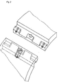
- the ring segments 1, 2 each have two diagonally opposed separating surfaces which are produced by spark erosion and are interrupted twice and run perpendicular to the end faces.
- the respective central surface sections in the circumferential direction are distanced by a grub screw 10, which was screwed in from a threaded hole of the meander in the right-hand segment 2 in FIG the left segment 1 just by the thickness of the spark erosion gap from the central radial surface section of the right segment 2.
- the corresponding cutting edges 7 of the respective segment halves 1, 2 lie against one another without joints.
- a dowel pin 5 is inserted into a corresponding radial fitting bore 8 formed by the adjacent ring segments in each coupling zone and then secured against falling out by the screw 6 with a washer.
- the cutting sleeve as a whole can be continuously adjusted axially on the smooth lower knife shaft according to the desired cutting width program, whereupon the radial clamping screw 3 is tightened and the non-ferrous metal clamping plate 9 below is gently pressed onto the smooth shaft. The procedure for removing the cutting sleeve is reversed.
Landscapes
- Life Sciences & Earth Sciences (AREA)
- Forests & Forestry (AREA)
- Engineering & Computer Science (AREA)
- Mechanical Engineering (AREA)
- Nonmetal Cutting Devices (AREA)
- Crushing And Pulverization Processes (AREA)
- Milling Processes (AREA)
- Shearing Machines (AREA)
Claims (5)
Priority Applications (4)
| Application Number | Priority Date | Filing Date | Title |
|---|---|---|---|
| EP86104425A EP0239657B1 (fr) | 1986-04-01 | 1986-04-01 | Anneau pour une cisaille à couteaux circulaires |
| AT86104425T ATE45536T1 (de) | 1986-04-01 | 1986-04-01 | Ring fuer die untermesserwelle in laengsschneidemaschinen. |
| DE8686104425T DE3665038D1 (en) | 1986-04-01 | 1986-04-01 | Ring for rotary slitting machines |
| SE8603225A SE8603225L (sv) | 1986-04-01 | 1986-07-25 | Ring for underknivaxel i rullskermaskin |
Applications Claiming Priority (1)
| Application Number | Priority Date | Filing Date | Title |
|---|---|---|---|
| EP86104425A EP0239657B1 (fr) | 1986-04-01 | 1986-04-01 | Anneau pour une cisaille à couteaux circulaires |
Publications (2)
| Publication Number | Publication Date |
|---|---|
| EP0239657A1 EP0239657A1 (fr) | 1987-10-07 |
| EP0239657B1 true EP0239657B1 (fr) | 1989-08-16 |
Family
ID=8195030
Family Applications (1)
| Application Number | Title | Priority Date | Filing Date |
|---|---|---|---|
| EP86104425A Expired EP0239657B1 (fr) | 1986-04-01 | 1986-04-01 | Anneau pour une cisaille à couteaux circulaires |
Country Status (4)
| Country | Link |
|---|---|
| EP (1) | EP0239657B1 (fr) |
| AT (1) | ATE45536T1 (fr) |
| DE (1) | DE3665038D1 (fr) |
| SE (1) | SE8603225L (fr) |
Families Citing this family (3)
| Publication number | Priority date | Publication date | Assignee | Title |
|---|---|---|---|---|
| ATE485141T1 (de) * | 2008-05-02 | 2010-11-15 | Wifag Maschf Ag | Geteiltes messer für eine untermesswelle in einer längsschneidemaschine |
| DE102009011331A1 (de) | 2009-03-05 | 2010-09-16 | H. Schönenberger GmbH | Axial geteiltes Ringmesser für eine Längsschneidevorrichtung |
| DE102009011330A1 (de) | 2009-03-05 | 2010-09-16 | H. Schönenberger GmbH | Rundmesser für eine Messerwelle einer Schneidvorrichtung |
Family Cites Families (7)
| Publication number | Priority date | Publication date | Assignee | Title |
|---|---|---|---|---|
| DE1250254B (de) * | 1967-09-14 | Jagenberg Werke A G , Dusseldorf | Zwischenring fur Messerwalzen an Langsschneidemaschiren | |
| US2083414A (en) * | 1936-06-06 | 1937-06-08 | Theodore A Wettig | Rail chuck for machine tools |
| US2491976A (en) * | 1946-01-17 | 1949-12-20 | Edward C Hauser | Detachable wheel |
| GB1245925A (en) * | 1967-09-29 | 1971-09-15 | Masson Scott Thrissell Eng Ltd | Improvements in or relating to the fitting of rings round cylindrical objects |
| US3871777A (en) * | 1972-12-22 | 1975-03-18 | L E Sauer Machine Co | Clamping means for split rotary anvil and the like |
| US3850069A (en) * | 1974-01-21 | 1974-11-26 | S & S Corrugated Paper Mach | Mounting of rotary split slitting knives |
| DE3042621C2 (de) * | 1980-11-12 | 1984-03-15 | Dienes Werke für Maschinenteile GmbH & Co KG, 5063 Overath | Geteilte Ringe für Längsschneidemaschinen |
-
1986
- 1986-04-01 AT AT86104425T patent/ATE45536T1/de not_active IP Right Cessation
- 1986-04-01 EP EP86104425A patent/EP0239657B1/fr not_active Expired
- 1986-04-01 DE DE8686104425T patent/DE3665038D1/de not_active Expired
- 1986-07-25 SE SE8603225A patent/SE8603225L/ not_active Application Discontinuation
Also Published As
| Publication number | Publication date |
|---|---|
| SE8603225D0 (sv) | 1986-07-25 |
| EP0239657A1 (fr) | 1987-10-07 |
| DE3665038D1 (en) | 1989-09-21 |
| ATE45536T1 (de) | 1989-09-15 |
| SE8603225L (sv) | 1987-10-02 |
Similar Documents
| Publication | Publication Date | Title |
|---|---|---|
| DE2619157C2 (de) | Ringscheibenförmiger Mahlkörper zum Einbau in einen Refiner zur Aufbereitung von Faserstoffbrei insbesondere für die Papierherstellung | |
| DE3044415C2 (de) | Elastische Kupplung zur Übertragung einer Drehbewegung | |
| EP0133320A2 (fr) | Tête porte-lame pour machine à tailler les roues dentées | |
| DE2348731C2 (de) | Kantenbearbeitungswerkzeug | |
| EP0008346A1 (fr) | Machine à fraiser les vilebrequins | |
| EP0132567B1 (fr) | Dispositif de serrage pour une meule annulaire | |
| EP0182037B1 (fr) | Couteau rotatif pour la granulation de boudins en plastique | |
| EP0239657B1 (fr) | Anneau pour une cisaille à couteaux circulaires | |
| DE69314749T2 (de) | Elektrodenverbindungsstelle zum Selbstzentrieren | |
| DE2808696C3 (de) | Klemmverbindung | |
| DE2139437B1 (de) | Vorrichtung zum gegenseitigen Ausrichten von einander zugeordne ten Maschinenteilen | |
| DE3529786A1 (de) | Backenfutter fuer werkzeugmaschinen | |
| DE3924884C2 (fr) | ||
| EP0170877B1 (fr) | Rotor pour métier à filer à fibres libérées et son procédé de fabrication | |
| EP0296594A2 (fr) | Méthode et dispositif d'alignement réciproque de galets de formage | |
| DE4433602A1 (de) | Gegenleiste für eine Perforiereinrichtung | |
| DE2846747B1 (de) | Praezisions-Streifenschneidmaschine | |
| DE2807120C2 (de) | Wälzfräser mit eingesetzten Schneiden | |
| DE2827391A1 (de) | Rotor fuer eine zerkleinerungsvorrichtung | |
| DE1192885B (de) | Keilverbindung zwischen Welle und Nabe | |
| EP0053277A1 (fr) | Cylindres pour groupes d'impression de presses rotatives | |
| DE19722839C1 (de) | Schneidbacke für Gewindeschere | |
| DE2558463C2 (de) | Dichtungs-Halterungsanordnung | |
| EP1117507B1 (fr) | Rectifieuse | |
| DE930605C (de) | Aus mehreren Einzelteilen zusammengesetzte Gewindestange od. dgl. |
Legal Events
| Date | Code | Title | Description |
|---|---|---|---|
| PUAI | Public reference made under article 153(3) epc to a published international application that has entered the european phase |
Free format text: ORIGINAL CODE: 0009012 |
|
| 17P | Request for examination filed |
Effective date: 19860410 |
|
| AK | Designated contracting states |
Kind code of ref document: A1 Designated state(s): AT DE FR GB IT SE |
|
| ITCL | It: translation for ep claims filed |
Representative=s name: ING. FISCHETTI WEBER |
|
| EL | Fr: translation of claims filed | ||
| 17Q | First examination report despatched |
Effective date: 19880428 |
|
| GRAA | (expected) grant |
Free format text: ORIGINAL CODE: 0009210 |
|
| AK | Designated contracting states |
Kind code of ref document: B1 Designated state(s): AT DE FR GB IT SE |
|
| REF | Corresponds to: |
Ref document number: 45536 Country of ref document: AT Date of ref document: 19890915 Kind code of ref document: T |
|
| REF | Corresponds to: |
Ref document number: 3665038 Country of ref document: DE Date of ref document: 19890921 |
|
| ITF | It: translation for a ep patent filed | ||
| ET | Fr: translation filed | ||
| GBT | Gb: translation of ep patent filed (gb section 77(6)(a)/1977) | ||
| PLBE | No opposition filed within time limit |
Free format text: ORIGINAL CODE: 0009261 |
|
| STAA | Information on the status of an ep patent application or granted ep patent |
Free format text: STATUS: NO OPPOSITION FILED WITHIN TIME LIMIT |
|
| 26N | No opposition filed | ||
| PGFP | Annual fee paid to national office [announced via postgrant information from national office to epo] |
Ref country code: FR Payment date: 19910328 Year of fee payment: 6 |
|
| PGFP | Annual fee paid to national office [announced via postgrant information from national office to epo] |
Ref country code: SE Payment date: 19910402 Year of fee payment: 6 Ref country code: GB Payment date: 19910402 Year of fee payment: 6 |
|
| PGFP | Annual fee paid to national office [announced via postgrant information from national office to epo] |
Ref country code: AT Payment date: 19910409 Year of fee payment: 6 |
|
| ITTA | It: last paid annual fee | ||
| PG25 | Lapsed in a contracting state [announced via postgrant information from national office to epo] |
Ref country code: GB Effective date: 19920401 Ref country code: AT Effective date: 19920401 |
|
| PG25 | Lapsed in a contracting state [announced via postgrant information from national office to epo] |
Ref country code: SE Effective date: 19920402 |
|
| GBPC | Gb: european patent ceased through non-payment of renewal fee | ||
| PG25 | Lapsed in a contracting state [announced via postgrant information from national office to epo] |
Ref country code: FR Effective date: 19921230 |
|
| REG | Reference to a national code |
Ref country code: FR Ref legal event code: ST |
|
| EUG | Se: european patent has lapsed |
Ref document number: 86104425.3 Effective date: 19921108 |
|
| PGFP | Annual fee paid to national office [announced via postgrant information from national office to epo] |
Ref country code: DE Payment date: 20020602 Year of fee payment: 17 |
|
| PG25 | Lapsed in a contracting state [announced via postgrant information from national office to epo] |
Ref country code: DE Free format text: LAPSE BECAUSE OF NON-PAYMENT OF DUE FEES Effective date: 20031101 |
|
| PG25 | Lapsed in a contracting state [announced via postgrant information from national office to epo] |
Ref country code: IT Free format text: LAPSE BECAUSE OF NON-PAYMENT OF DUE FEES;WARNING: LAPSES OF ITALIAN PATENTS WITH EFFECTIVE DATE BEFORE 2007 MAY HAVE OCCURRED AT ANY TIME BEFORE 2007. THE CORRECT EFFECTIVE DATE MAY BE DIFFERENT FROM THE ONE RECORDED. Effective date: 20050401 |