EP0240068A2 - Petit appareil ménager entraîné au moyen d'un moteur synchrone monophasé - Google Patents
Petit appareil ménager entraîné au moyen d'un moteur synchrone monophasé Download PDFInfo
- Publication number
- EP0240068A2 EP0240068A2 EP87200530A EP87200530A EP0240068A2 EP 0240068 A2 EP0240068 A2 EP 0240068A2 EP 87200530 A EP87200530 A EP 87200530A EP 87200530 A EP87200530 A EP 87200530A EP 0240068 A2 EP0240068 A2 EP 0240068A2
- Authority
- EP
- European Patent Office
- Prior art keywords
- scanning
- rotation
- cam
- household appliance
- rotor
- Prior art date
- Legal status (The legal status is an assumption and is not a legal conclusion. Google has not performed a legal analysis and makes no representation as to the accuracy of the status listed.)
- Withdrawn
Links
Images

Classifications
-
- B—PERFORMING OPERATIONS; TRANSPORTING
- B26—HAND CUTTING TOOLS; CUTTING; SEVERING
- B26B—HAND-HELD CUTTING TOOLS NOT OTHERWISE PROVIDED FOR
- B26B19/00—Clippers or shavers operating with a plurality of cutting edges, e.g. hair clippers, dry shavers
- B26B19/28—Drive layout for hair clippers or dry shavers, e.g. providing for electromotive drive
- B26B19/282—Motors without a rotating central drive shaft, e.g. linear motors
-
- B—PERFORMING OPERATIONS; TRANSPORTING
- B26—HAND CUTTING TOOLS; CUTTING; SEVERING
- B26B—HAND-HELD CUTTING TOOLS NOT OTHERWISE PROVIDED FOR
- B26B19/00—Clippers or shavers operating with a plurality of cutting edges, e.g. hair clippers, dry shavers
- B26B19/28—Drive layout for hair clippers or dry shavers, e.g. providing for electromotive drive
-
- H—ELECTRICITY
- H02—GENERATION; CONVERSION OR DISTRIBUTION OF ELECTRIC POWER
- H02K—DYNAMO-ELECTRIC MACHINES
- H02K7/00—Arrangements for handling mechanical energy structurally associated with dynamo-electric machines, e.g. structural association with mechanical driving motors or auxiliary dynamo-electric machines
- H02K7/06—Means for converting reciprocating motion into rotary motion or vice versa
-
- H—ELECTRICITY
- H02—GENERATION; CONVERSION OR DISTRIBUTION OF ELECTRIC POWER
- H02K—DYNAMO-ELECTRIC MACHINES
- H02K7/00—Arrangements for handling mechanical energy structurally associated with dynamo-electric machines, e.g. structural association with mechanical driving motors or auxiliary dynamo-electric machines
- H02K7/10—Structural association with clutches, brakes, gears, pulleys or mechanical starters
- H02K7/118—Structural association with clutches, brakes, gears, pulleys or mechanical starters with starting devices
- H02K7/1185—Structural association with clutches, brakes, gears, pulleys or mechanical starters with starting devices with a mechanical one-way direction control, i.e. with means for reversing the direction of rotation of the rotor
-
- Y—GENERAL TAGGING OF NEW TECHNOLOGICAL DEVELOPMENTS; GENERAL TAGGING OF CROSS-SECTIONAL TECHNOLOGIES SPANNING OVER SEVERAL SECTIONS OF THE IPC; TECHNICAL SUBJECTS COVERED BY FORMER USPC CROSS-REFERENCE ART COLLECTIONS [XRACs] AND DIGESTS
- Y10—TECHNICAL SUBJECTS COVERED BY FORMER USPC
- Y10T—TECHNICAL SUBJECTS COVERED BY FORMER US CLASSIFICATION
- Y10T74/00—Machine element or mechanism
- Y10T74/12—Gyroscopes
Definitions
- the invention relates to a small household appliance which is driven by a single-phase synchronous motor, the output shaft of which drives a load with a work function which is not dependent on the direction of rotation, a different operating noise and vibrations occurring depending on the direction of rotation.
- Small household appliances are known in which the work function is not dependent on the direction of rotation of the motor. This applies to all devices in which the working movement is a reciprocating movement, such as, for example, electric shavers with a reciprocating bottom knife or hair clippers.
- These reciprocating movements of the shear tool can be generated with the aid of an oscillating armature motor or an electric motor with a rotating armature, for example with a single-phase synchronous motor.
- Such a drive for a hair clipper is described, for example, in the magazine ETZ, volume 30, 1978, H2, pages 56 to 60.
- the different noises can depend on a movement behavior of the motor which is dependent on the direction of rotation. Asymmetry can be observed especially when converting rotary movements into oscillatory movements.
- the object is achieved in that the transmission path has a backstop and that the rotor is forced by means of this backstop will rotate in the direction in which the more favorable operating noise and / or less vibration occur.
- the motor therefore always starts in the direction of rotation which is favorable for the noise and vibrations, and the user thus always has the same noise impression and the same overall perceptions of the operating behavior. The user is no longer unsettled about the quality of the device.
- the single-phase synchronous motor with its transmission path to the load is designed so that the more favorable operating noise occurs in the direction of rotation in which the torque exerted by the stator current on the rotor becomes zero before the magnetic adhesive torque when there is no current Stator coils is zero and leads to a stable rest position, and that the rotor is forced by means of a backstop to rotate in this positive direction.
- the blocking effect of the backstop is exerted on one of these transmission elements.
- the locking action of the backstop has a milder effect and causes less noise.
- the transmission members are formed by a cam scanning gear, which consists of a cam attached to the rotor shaft and a cam wheel, which is rotatably supported and which is resiliently pressed against the cam, the locking action on this scanning wheel exercised by locking a direction of rotation of this scanning wheel.
- the locking effect is exerted on one of the scanning wheels.
- the scanning wheel, on which the blocking effect is exerted is indeed a link in the chain of the transmission links, but does not transmit any forces to the driven part by rotation; the rotatability only ensures that the cam rolls off easily on the cam scanner or swivel arm.
- the blocking effect of the backstop thus acts on the side of the actual power transmission path and thus acts on the single-phase synchronous motor by increasing friction and not directly in a form-fitting manner.
- the locking effect is generated by means of a resilient locking element which presses against an end face of the scanning wheel, on which a locking lug is provided, against which the locking pawl strikes in the undesired direction of rotation, the locking pawl being a plastic injection molded part , which is mounted on the same transmission element as the scanning wheel.
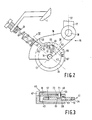
- Fig. L shows a double-arm cam scanner drive for a vibration device, such as a dry shave apparatus, with a scanning roller scanning a cam.
- a synchronous motor 2 with its permanently magnetic rotor 3 is mounted on an assembly wall 1 of the dry shaving apparatus.
- the rotor 3 is rotatably arranged in the air gap 4a between pole shoes 4b.
- the excitation coils 4d are pushed onto the U-shaped stator iron 4c with the pole shoes 4b.
- a drive shaft 5 of the synchronous motor protrudes perpendicularly from the rotor 3 and points upward out of the plane of the drawing.
- a mirror-image cam 7 is arranged on the drive shaft 5 and has a contour 8 such that a lower knife 9 of the dry shaving apparatus experiences a sinusoidal deflection when the cam 7 is rotated, depending on the angle of rotation of the cam.
- the longer center line of the cam 7 is designated l0.
- the double-arm cam scanner l5 has two lever arms l6 and l7, which can be pivoted about a common pivot bearing l8 at the break point between the two lever arms l6 and l7.
- the lever arms l6 and l7 which are rigidly connected to one another, enclose an angle of approximately l40 °, which is measured between the connecting line 36 between the roller bearing l4 and the pivot bearing l8 and a center line 37 of the lever arm l7.
- a pressure spring 2l presses against the lever arm l6, the pretension of which can be adjusted with the aid of an adjusting screw 23.
- the center line 24 of the pressure spring 2l runs through the motor shaft 5 when the scanner l5 is in the center position and is perpendicular to the connecting line 36 of the pivot bearing l8 and roller bearing l4.
- the lever arm l7 of the double-arm scanner l5 is provided with a driver 25 which is encompassed by grippers 27 of the lower knife 9.
- the lower knife 9 is displaceable in the direction of a double arrow 33 with the aid of indicated bearings 3l.
- the scanning wheel l3 is pressed with its surface 34 against the surface 8 of the cam 7 via an elastic ring 43.
- the pressing force is dimensioned so that on the one hand the scanning wheel l3 cannot lift off the cam 7 at any time, but on the other hand the pressing force does not become so great that the rotating movement of the rotor is impaired.
- Such an arrangement with a single-phase synchronous motor and a downstream load transmission path generally shows different noise and vibration behavior, depending on the direction of rotation of the motor. These are due on the one hand to asymmetries in the design of the stator pole arcs of the single-phase synchronous motor and on the other hand to asymmetries with regard to the direction of rotation in the mechanical transmission path between the motor and the load.
- the positive direction of rotation is that in which the stator current flows onto the rotor
- the practiced torque is zero before the magnetic adhesive torque is zero when the stator coils are de-energized and at the same time leads to a stable rest position.
- the magnetic adhesive torque is the moment that the rotor magnet opposes to twisting when the stator coils are de-energized.
- the rotor In the stable rest position, in the case of de-energized stator coils, the rotor is in a certain position relative to the stator poles 4b due to the magnetic force of the rotor magnet, which deviates from the main direction of the stator field by a positive angle.
- a backstop 4l is provided, which is only roughly indicated in Fig. 1 and is shown in Fig. 2 in plan view and in Fig. 3 in section along a line III-III.
- This backstop 4l acts between the lever arm l6 of the double-arm cam scanner l5 and the scanning wheel l3, which is provided on its surface with a friction ring 43, for example made of rubber.
- the backstop 4l consists of a locking element 45, which is constructed from a fastening pin 47, a locking hook 49 and a resilient, Z-shaped bridge 5l connecting the fastening pin 47 and the locking hook 49.
- the fastening pin 47 is captively inserted in a dovetail guide 53 of the lever arm l6.
- the locking hook 49 freely moves through a further hole 55 in the lever arm l6.
- the resilient bridge 5l constantly presses the locking hook 49 against an end face 57 of the scanning wheel 13 (FIG. 3).
- the scanning wheel l3 is provided with a depression 59 in the region of its end face 57.
- This recess 59 points in Circumferential direction two differently formed walls 6l and 63.
- the wall 6l represents a blocking lug for the locking hook 49 and therefore runs perpendicular to the end face 57.
- the other wall 63 represents an inclined plane over which the locking hook 49 can slide. This backstop now works depending on the direction of rotation of the motor. If the rotor 3 rotates the scanning wheel l3 in the direction of an arrow 65 via the cams 7, then the locking hook 49 runs continuously out of the depression 59 via the inclined wall 63.
- the locking action of the pawl 4l is now selected so that the rotor 3 can only start in the favorable direction of rotation, ie in the direction of rotation with less noise. This ensures that the motor and the drive are only ever operated in the favorable direction of rotation, this direction of rotation being the one in which the noise development on the load transmission path 7, l3, l6, l7, 27, 9 is pleasant and the least.
- the rear wall 7l of the locking hook 49 should be against the wall 73 of the hole 55 can preferably be supported elastically.
- the spring constant and mass of the pawl 4l should also be adjusted so that the bounce is as low as possible during operation of the device and the pawl is placed as softly as possible on the scanning wheel l3.
- a resilient, Z-shaped bridge 5l in the form of a plastic part is particularly suitable.
- the contact pressure of the spring should also be dimensioned so that the motor movement is stabilized and additional damping means of the motor can be dispensed with.
- the desired contact pressure can be achieved in that the lever is elastic and is under a certain pretension.
- the pressing of a roller by means of a spring can be dispensed with.
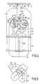
- the single-phase synchronous motor 2 drives with its rotor shaft 5, via the mirror-image cams 7, two scanning rollers 8l, 8la to which are mounted on the free ends of partial arms 82, 82a of a swivel arm 83.
- the swivel arm 83 is in turn pivotally mounted on the frame 1 about an axis 84.
- the scanning rollers 8l and 8la scan the contour 8 of the cam 7 by constant contact.
- the fork arms 27 of the knife block 9 engage on the output end 86 of the swivel arm 83.
- both partial arms 82 and 82a or only one of the two can be designed to be elastic. It is also possible to provide the bearings in the region of the roller axis 87 and 87a with elasticity or to provide the outer surface of one or both rollers 8l, 8la with an elastic covering 88 in order to bring about a certain compensation in order to avoid jamming.
- the connecting lines 89 between the motor / cam axis 5 and the roller axes 87, 87a form an angle 0 with one another in the center position shown, which is 90 °. Since the movement that is forced on the rollers 8l, 8la by the cam 7, originally starting from the center position of the rollers 8l, 8la, is based on a linearly oscillating movement in the direction of the connecting lines 89 of the cam and roller axis, the center 90 is preferably the The pivot axis 84 of the pivot arm 83 is the center point of a circle which roughly affects the two roller axes 87, 87a when the rollers 8l, 8la are in the center position.
- This circular path should nestle as closely as possible to the originally linearly oscillating roller path.
- the swivel arm axis 84 or the center line 9la of the motor laminated core forms the bisector between the connecting lines 89 of the roller axis 87, 87a and the cam axis 5, this center line 9la running through the cam axis 5.
- the connecting lines 92 between the swivel arm axis 84 and the roller axes 87, 87a and the connecting lines 89 between the cam axis 5 and the roller axes 87, 87a should preferably be perpendicular to one another. Deviations from the linear path lead to distortions.
- the transmission path of the device is provided with a backstop 4l, which corresponds to that of FIGS. 2 and 3.
- This backstop 4l is indicated in Fig. 4 in the arm 82.
- Fig. 5 shows the backstop 4l more clearly.
- the backstop 4l acts between the partial arm 82 and the scanning wheel 8l; it consists of a locking element 45 molded from plastic, which consists of a fastening pin 47, a locking hook 49 and a resilient, Z-shaped bridge 5l connecting these parts.
- the fastening pin 47 is captively inserted into a dovetail guide 53 of the arm section 82.
- the locking hook 49 moves freely through a hole 55 in the arm 82.
- the resilient bridge 5l constantly presses the locking hook 49 against the end face 57 of the scanning wheel 8l.
- the scanning wheel is provided on the end face 57 with a recess 59 which runs freely on the end face 57 in an inclined plane 63 in the desired direction of rotation and has a blocking nose 6l against the direction of rotation.
Landscapes
- Engineering & Computer Science (AREA)
- Life Sciences & Earth Sciences (AREA)
- Forests & Forestry (AREA)
- Mechanical Engineering (AREA)
- Power Engineering (AREA)
- Connection Of Motors, Electrical Generators, Mechanical Devices, And The Like (AREA)
- Motor And Converter Starters (AREA)
- Synchronous Machinery (AREA)
Applications Claiming Priority (2)
| Application Number | Priority Date | Filing Date | Title |
|---|---|---|---|
| DE3610772 | 1986-03-29 | ||
| DE3610772A DE3610772C1 (de) | 1986-03-29 | 1986-03-29 | Kleines Haushaltsgeraet,das mittels eines Einphasensynchronmotors angetrieben ist |
Publications (2)
| Publication Number | Publication Date |
|---|---|
| EP0240068A2 true EP0240068A2 (fr) | 1987-10-07 |
| EP0240068A3 EP0240068A3 (fr) | 1988-01-13 |
Family
ID=6297610
Family Applications (1)
| Application Number | Title | Priority Date | Filing Date |
|---|---|---|---|
| EP87200530A Withdrawn EP0240068A3 (fr) | 1986-03-29 | 1987-03-23 | Petit appareil ménager entraíné au moyen d'un moteur synchrone monophasé |
Country Status (4)
| Country | Link |
|---|---|
| US (1) | US4760297A (fr) |
| EP (1) | EP0240068A3 (fr) |
| JP (1) | JPS62236341A (fr) |
| DE (1) | DE3610772C1 (fr) |
Families Citing this family (7)
| Publication number | Priority date | Publication date | Assignee | Title |
|---|---|---|---|---|
| DE3404297C2 (de) * | 1984-02-08 | 1986-04-17 | Philips Patentverwaltung Gmbh, 2000 Hamburg | Vorrichtung zum Antreiben eines Vibrationsteiles, insbesondere eines kleinen Haushaltsgerätes |
| DE3822332A1 (de) * | 1988-07-01 | 1990-01-04 | Philips Patentverwaltung | Haushaltsvibrationsgeraet |
| DE3917849C1 (fr) * | 1989-06-01 | 1990-11-29 | Braun Ag, 6000 Frankfurt, De | |
| NL9100439A (nl) * | 1991-03-12 | 1992-10-01 | Philips Nv | Scheerapparaat. |
| DE10038209A1 (de) * | 2000-08-04 | 2002-02-14 | Philips Corp Intellectual Pty | Elektrisches Gerät mit einem Aktuator |
| US7819488B2 (en) * | 2006-10-09 | 2010-10-26 | Samsung Electronics Co., Ltd. | Door opening device and refrigerator having the same |
| US20160226364A1 (en) * | 2015-01-30 | 2016-08-04 | Sunbeam Products, Inc. | Electric Hair Clipper/Trimmer |
Family Cites Families (9)
| Publication number | Priority date | Publication date | Assignee | Title |
|---|---|---|---|---|
| GB419767A (en) * | 1933-07-26 | 1934-11-19 | Primus Otto Dorer | Improvements in or relating to starting devices for synchronous electric motors |
| DE2632586C2 (de) * | 1976-07-20 | 1983-05-19 | Gesellschaft für Kernverfahrenstechnik mbH, 5170 Jülich | Verfahren und Vorrichtung zum Durchlaufen kritischer Drehzahlen langgestreckter Rotoren |
| CH619329A5 (fr) * | 1977-07-15 | 1980-09-15 | Sodeco Compteurs De Geneve | |
| NL7907587A (nl) * | 1979-10-12 | 1981-04-14 | Coop Landbouw Aan Verkoop | Zeefinrichting voor het scheiden van een mengsel van deeltjesvormig materiaal in componenten van verschillende grootte. |
| AT385936B (de) * | 1980-07-28 | 1988-06-10 | Philips Nv | Trockenrasierapparat |
| CH661159A5 (de) * | 1982-06-01 | 1987-06-30 | Sodeco Compteurs De Geneve | Drehrichtungssperre fuer den rotor eines synchronmotors. |
| DE3404296A1 (de) * | 1984-02-08 | 1985-08-14 | Philips Patentverwaltung Gmbh, 2000 Hamburg | Antriebsvorrichtung fuer einen vibrationstrockenrasierapparat mit einer scherfolie und einem hin und her bewegbaren schneidelement und antrieb durch einen einphasensynchronmotor |
| US4527671A (en) * | 1984-02-27 | 1985-07-09 | Sanyei Corporation | Rotary direction regulator for synchronous electric motor |
| DE3521526A1 (de) * | 1985-06-15 | 1986-12-18 | Danfoss A/S, Nordborg | Motor-verdichter-aggregat |
-
1986
- 1986-03-29 DE DE3610772A patent/DE3610772C1/de not_active Expired
-
1987
- 1987-03-23 EP EP87200530A patent/EP0240068A3/fr not_active Withdrawn
- 1987-03-26 JP JP62070516A patent/JPS62236341A/ja active Pending
- 1987-03-31 US US07/033,125 patent/US4760297A/en not_active Expired - Fee Related
Also Published As
| Publication number | Publication date |
|---|---|
| EP0240068A3 (fr) | 1988-01-13 |
| US4760297A (en) | 1988-07-26 |
| DE3610772C1 (de) | 1987-06-04 |
| JPS62236341A (ja) | 1987-10-16 |
Similar Documents
| Publication | Publication Date | Title |
|---|---|---|
| EP0861141B1 (fr) | Rasoir electrique | |
| EP0636349A1 (fr) | Brosse à dents | |
| EP0656489A1 (fr) | Dispositif pour transformer une rotation au moyen d'un excentrique en un mouvement oscillant | |
| EP3369158B1 (fr) | Système de balais d'un motoeur electrique | |
| EP0349076A2 (fr) | Appareil vibratoire de ménage | |
| WO2002095171A1 (fr) | Dispositif de commande | |
| DE3610772C1 (de) | Kleines Haushaltsgeraet,das mittels eines Einphasensynchronmotors angetrieben ist | |
| EP0495546A1 (fr) | Rasoir électrique | |
| EP3715570A1 (fr) | Installation de porte coulissante | |
| DE3610770C2 (fr) | ||
| DE2513007A1 (de) | Vorrichtung mit einem synchronmotor | |
| DE3610771C1 (de) | Vorrichtung zur Gleichlaufverbesserung der Umlaufbewegung des Rotors eines Einphasensynchronmotors | |
| DE3404297C2 (de) | Vorrichtung zum Antreiben eines Vibrationsteiles, insbesondere eines kleinen Haushaltsgerätes | |
| DE3240211A1 (de) | Walzenzufuehrungseinrichtung | |
| DE3207063A1 (de) | Kleinpresse | |
| DE10146568A1 (de) | Bürstenhalter für eine elektrische Maschine | |
| DE3404299C2 (de) | Antriebsvorrichtung für ein Vibrationsgerät | |
| DE1931657A1 (de) | Programmsteuergeraet fuer elektrische Haushaltsmaschinen | |
| DE102008031134B4 (de) | Oszillierender Rotationsmotor sowie elektrisch betriebenes Kleingerät hierzu | |
| EP1629512B1 (fr) | Dispositif de couplage pour appareils munis d'elements de commutation rotatifs | |
| EP1913615B1 (fr) | Dispositif tendeur | |
| EP0038287A1 (fr) | Poignée rotative pour commande à la main d'une propulsion d'énergie | |
| DE3513803A1 (de) | Elektrischer schalter | |
| DE102013213303A1 (de) | Elektrischer Schalter mit Umwandlung einer Drehbewegung in eine oszillierende Bewegung einer Schalterkomponente | |
| DE4038839C1 (en) | Electric hair trimmer-drive - uses two arm lever to convert rotation of electric motor into reciprocating motion of cutting head |
Legal Events
| Date | Code | Title | Description |
|---|---|---|---|
| PUAI | Public reference made under article 153(3) epc to a published international application that has entered the european phase |
Free format text: ORIGINAL CODE: 0009012 |
|
| AK | Designated contracting states |
Kind code of ref document: A2 Designated state(s): DE FR GB |
|
| PUAL | Search report despatched |
Free format text: ORIGINAL CODE: 0009013 |
|
| AK | Designated contracting states |
Kind code of ref document: A3 Designated state(s): DE FR GB |
|
| 17P | Request for examination filed |
Effective date: 19880617 |
|
| 17Q | First examination report despatched |
Effective date: 19910226 |
|
| STAA | Information on the status of an ep patent application or granted ep patent |
Free format text: STATUS: THE APPLICATION HAS BEEN WITHDRAWN |
|
| 18W | Application withdrawn |
Withdrawal date: 19910606 |
|
| RIN1 | Information on inventor provided before grant (corrected) |
Inventor name: STEINER, PETER ERWIN Inventor name: SCHEMMANN, HUGO, DR. |