EP0240404A2 - Ineinandergreifende Konstruktionselemente - Google Patents
Ineinandergreifende Konstruktionselemente Download PDFInfo
- Publication number
- EP0240404A2 EP0240404A2 EP87400629A EP87400629A EP0240404A2 EP 0240404 A2 EP0240404 A2 EP 0240404A2 EP 87400629 A EP87400629 A EP 87400629A EP 87400629 A EP87400629 A EP 87400629A EP 0240404 A2 EP0240404 A2 EP 0240404A2
- Authority
- EP
- European Patent Office
- Prior art keywords
- elements
- width
- element according
- double
- horizontal
- Prior art date
- Legal status (The legal status is an assumption and is not a legal conclusion. Google has not performed a legal analysis and makes no representation as to the accuracy of the status listed.)
- Withdrawn
Links
- 238000010276 construction Methods 0.000 title claims description 7
- 238000005192 partition Methods 0.000 description 3
- 241000238876 Acari Species 0.000 description 1
- 238000004026 adhesive bonding Methods 0.000 description 1
- 239000011230 binding agent Substances 0.000 description 1
- 239000011248 coating agent Substances 0.000 description 1
- 238000000576 coating method Methods 0.000 description 1
- 239000002131 composite material Substances 0.000 description 1
- 238000009434 installation Methods 0.000 description 1
- 230000014759 maintenance of location Effects 0.000 description 1
- 238000004519 manufacturing process Methods 0.000 description 1
- 239000000463 material Substances 0.000 description 1
- 238000000465 moulding Methods 0.000 description 1
- 230000002093 peripheral effect Effects 0.000 description 1
- 239000002689 soil Substances 0.000 description 1
- 239000004575 stone Substances 0.000 description 1
- XLYOFNOQVPJJNP-UHFFFAOYSA-N water Substances O XLYOFNOQVPJJNP-UHFFFAOYSA-N 0.000 description 1
Images

Classifications
-
- E—FIXED CONSTRUCTIONS
- E04—BUILDING
- E04B—GENERAL BUILDING CONSTRUCTIONS; WALLS, e.g. PARTITIONS; ROOFS; FLOORS; CEILINGS; INSULATION OR OTHER PROTECTION OF BUILDINGS
- E04B2/00—Walls, e.g. partitions, for buildings; Wall construction with regard to insulation; Connections specially adapted to walls
- E04B2/02—Walls, e.g. partitions, for buildings; Wall construction with regard to insulation; Connections specially adapted to walls built-up from layers of building elements
- E04B2/04—Walls having neither cavities between, nor in, the solid elements
- E04B2/12—Walls having neither cavities between, nor in, the solid elements using elements having a general shape differing from that of a parallelepiped
-
- E—FIXED CONSTRUCTIONS
- E04—BUILDING
- E04B—GENERAL BUILDING CONSTRUCTIONS; WALLS, e.g. PARTITIONS; ROOFS; FLOORS; CEILINGS; INSULATION OR OTHER PROTECTION OF BUILDINGS
- E04B2/00—Walls, e.g. partitions, for buildings; Wall construction with regard to insulation; Connections specially adapted to walls
- E04B2/02—Walls, e.g. partitions, for buildings; Wall construction with regard to insulation; Connections specially adapted to walls built-up from layers of building elements
- E04B2002/0202—Details of connections
- E04B2002/0232—Undercut connections, e.g. using undercut tongues and grooves
Definitions
- the invention relates to a self-locking construction element, of the paving stone, concrete block, beam, etc. type which can, by its shape, fit together with identical elements so that they block each other to constitute a flat surface or not, forming for example a paving, a partition, a wall, a staircase, etc ...
- the element of the invention is characterized in that it is produced in the form of a double "T" assembled by the free end of their vertical branch, the free ends of the horizontal branches of these two T being provided with extensions parallel to the vertical branches and directed towards each other, two by two.
- the width of the horizontal branches, the width and the height of each extension, the spacing of each extension of the vertical branch are equal to each other, the spacing of two facing extensions being equal to two times this width.
- the width of the vertical branch is a multiple of the width of the horizontal branch.
- the invention forms a very long profile with a double-T section, suitable for being embedded and locked, by its ends, in an assembly of elements of corresponding section, of a wall or the like.
- it comprises two double-T elements connected by at least one flat surface forming a shelf and connecting the horizontal branches of these two elements and this over part of their thickness.
- a rectangular plate called facing is provided on a part of one of the faces of the element, this plate covering and being delimited by the vertical branch of the double T, by half of each of the horizontal branches and by the two extensions of these two horizontal branch halves.
- the present invention therefore has the aim of producing an element which can be assembled with other similar elements, and this with or without a binder, so as to constitute the surface of a floor, a partition, a wall, etc ..., the dimensions of this element being able to vary according to the applications but being preferably established so as to be able to be handled by a man.
- this element can be very diverse depending on the applications (concrete, expanded or unexpanded plastic, composite material, etc.), this element also being able to be tinted in the mass or on the surface, or even to be provided with a surface coating. , of structure, nature or particular color.
- the basic element according to the invention is shown in Figure 1 and is defined by a double T shape whose vertical branches 1 are connected to each other by their free end, while the horizontal branches 2 are provided at their free ends with extensions 3 which, being parallel to the vertical branch 1, are oriented two by two towards each other.
- the width of the vertical branches 1, horizontal 2 and extensions 3 are equal, and are also equal to the height of the extensions and the spacing of these extensions relative to the vertical branches 1.
- the spacing 4 of two extensions 3 opposite is equal to twice this width.
- angles of this element are straight, the angles adjoining the upper face can however be slightly rounded or provided with a flat.
- Figure 3 shows an assembly of these elements.
- the vertical branch 1 is of a width equal to the width of the horizontal branches 2.
- this vertical branch may have a width equal to a multiple of the width of the horizontal branches, as shown in Figures 4, 5 and 6.
- the vertical branch is formed by two parallel branches 5 1 , 5 2 whose width and their spacing 5 3 is equal to the width of the horizontal branches 2.
- this element of FIG. 4 can be assembled with elements identical to itself or with other elements whose width of the vertical branch is any multiple of the width of the branch 1 of l basic element.
- the vertical branch of the element has four pillars 6 1 , 6 2 , 6 3 and 6 4 whose width is equal to their spacing, as well as to the width of the horizontal branches 2.
- the element comprises only two pillars 7 1 , 7 2 forming the vertical branch of the T, the width of these pillars 7 1 , 7 2 corresponding to the width of the horizontal branches 2 and l 'spacing of these two pillars being a multiple of this width.
- FIGS. 4, 5 and 6 provided with a vertical branch of the double T which is hollowed out, can be used in the manufacture of surfaces having a particular decorative aspect. It can also be implemented for the realization of surfaces ensuring the retention of soil by allowing the flow of water, or even allowing the installation, in the hollowed out areas, of posts, pillars of support, etc ... entering the construction of a building.
- the surface produced by the assembly of the elements as described generally requires a finishing border eliminating the recesses such as 8 (see FIG. 3) remaining at the periphery of the assembly.
- partial elements may be produced from the basic element of FIG. 1 or from the elements of FIGS. 4, 5 and 6 in order to fill these recesses.
- the element of Figure 1 can be sectioned along the line A-A to form elements in "T". It can also be sectioned along a line B-B in order to produce corner elements 9, two of which will fill each recess 8 or else in order to produce elements 10 also ensuring the peripheral locking of the assembly.
- one of the ends of a horizontal branch 2 is connected by an oblique side 10 to the vertical branch 1.
- This element is assembled with elements in accordance with those of FIGS. 1, 4, 5, 6 in any number according to the desired covered surface and the edge of this assembly is ensured by elements of suitable shape.
- elements 15 obtained by elements substantially conforming to that of FIG. 1 sectioned along the line BB are used, elements 16 which correspond to the element of FIG. 1, except that one of the branches horizontal 16 1 is raised to form a raised border connected to the plane of the element by a curved surface.
- elements 17 combining both the two elements 15 and 16 and having for this purpose (see also FIG. 9) a raised horizontal branch 17 1 connected by curved surfaces I7 2 , 17 3 to the base plane of the element.
- the basic element also makes it possible to produce shelves 18 capable of fitting into a wall produced by an assembly of elements in accordance with the invention.
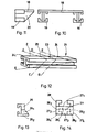
- This tablet 18 has at its two ends mites (FIG. 10) of the double T elements 19 conforming to that of FIG. 1, the shelf 18 however being offset from one side of the elements 19 (FIG. 11) so as to be connected by an oblique plane 20 to these elements of base 19, the rear part of these base elements 19 thus being able to be embedded in a partition or a wall, while the shelf 18 is projecting.
- the basic element of FIG. 1 can be made of various thicknesses depending on the function that it must fulfill, this thickness possibly being such that the element constitutes a profile 21 (see FIG. 12) that can constitute a beam entering the construction of a building.
- this beam 21 is sectioned by two parallel oblique planes CC and DD, an element 23 is obtained whose cross section is in accordance with that of the element in FIG. 1, and two opposite faces of which are oblique so that the assembly of elements of this type allows the realization of oblique surfaces.
- this beam 21 by cutting this beam 21 along the line EE, one obtains an element 24 capable of being embedded by its end 24 1 in a wall obtained by the assembly of elements according to the invention, while the upper face 25 the profile, which is formed by the horizontal branch of the T, may constitute a stair step.
- FIG. 13 there is also shown an element which can constitute the nose of a stair step and, in this case, the vertical branch 26 of the double T has an oblique plane 26 1 leading to the horizontal branch 26 2 .
- the surfaces produced by the assembly of the element in accordance with the invention will reveal a T-shaped entanglement of these elements one inside the other.
- These elements may however (see FIG. 14) be provided with a plate 27 capable of constituting a facing, this plate having either come from molding with the elements 28, or fixed by clipping or gluing on one of the faces of these elements.
- This facing plate 27 is rectangular in shape and covers substantially half of one of the faces of the element 28 so that one of the sides 27 1 of this plate covers the vertical branch 28 1 of the element, while that the other three sides 27 2 , 27 3 ′ 2 7 4 are delimited and completely cover half of the horizontal branches 28 2 and the two opposite extensions 28 3 and 2 8 4 .
Landscapes
- Engineering & Computer Science (AREA)
- Architecture (AREA)
- Physics & Mathematics (AREA)
- Electromagnetism (AREA)
- Civil Engineering (AREA)
- Structural Engineering (AREA)
- Finishing Walls (AREA)
- Steps, Ramps, And Handrails (AREA)
- Joining Of Building Structures In Genera (AREA)
Applications Claiming Priority (2)
| Application Number | Priority Date | Filing Date | Title |
|---|---|---|---|
| FR8604868 | 1986-04-04 | ||
| FR8604868A FR2596792B1 (fr) | 1986-04-04 | 1986-04-04 | Element de construction autoverrouillable |
Publications (2)
| Publication Number | Publication Date |
|---|---|
| EP0240404A2 true EP0240404A2 (de) | 1987-10-07 |
| EP0240404A3 EP0240404A3 (de) | 1988-10-05 |
Family
ID=9333919
Family Applications (1)
| Application Number | Title | Priority Date | Filing Date |
|---|---|---|---|
| EP87400629A Withdrawn EP0240404A3 (de) | 1986-04-04 | 1987-03-20 | Ineinandergreifende Konstruktionselemente |
Country Status (2)
| Country | Link |
|---|---|
| EP (1) | EP0240404A3 (de) |
| FR (1) | FR2596792B1 (de) |
Cited By (5)
| Publication number | Priority date | Publication date | Assignee | Title |
|---|---|---|---|---|
| EA008961B1 (ru) * | 2006-04-21 | 2007-10-26 | Юрий Петрович Свирин | Строительный блок, его применение в качестве строительного элемента для безрастворной кладки стеновых сооружений, в качестве облицовочного элемента и в качестве элемента вентилируемых фасадов и способ безрастворной кладки стеновых сооружений |
| RU2338037C1 (ru) * | 2007-03-13 | 2008-11-10 | Юрий Анатольевич Ландин | Мозаичная конструкция |
| EA012663B1 (ru) * | 2007-09-12 | 2009-12-30 | Юрий Петрович Свирин | Система строительных блоков (варианты), строительный блок из состава системы и способ сооружения многослойной стеновой конструкции |
| CN105220814A (zh) * | 2015-09-29 | 2016-01-06 | 成都市凤庭环能科技有限公司 | 一种拼接空心砖 |
| WO2025040665A1 (en) * | 2023-08-22 | 2025-02-27 | Allwood Architectural Joinery Limited | Modular construction system and interconnectable block therefore |
Families Citing this family (1)
| Publication number | Priority date | Publication date | Assignee | Title |
|---|---|---|---|---|
| WO2008094026A1 (fr) * | 2006-09-19 | 2008-08-07 | Auyelbay Baltabaevich Medetov | Bloc de maçonnerie |
Family Cites Families (2)
| Publication number | Priority date | Publication date | Assignee | Title |
|---|---|---|---|---|
| GB2152547B (en) * | 1984-01-11 | 1987-12-16 | Kenneth Mckenzie Brown | Interconnecting building blocks |
| DE3507243A1 (de) * | 1985-03-01 | 1985-11-07 | Ernst Dipl.-Ing. 3300 Braunschweig Dießl | Allround - baustein |
-
1986
- 1986-04-04 FR FR8604868A patent/FR2596792B1/fr not_active Expired - Lifetime
-
1987
- 1987-03-20 EP EP87400629A patent/EP0240404A3/de not_active Withdrawn
Cited By (5)
| Publication number | Priority date | Publication date | Assignee | Title |
|---|---|---|---|---|
| EA008961B1 (ru) * | 2006-04-21 | 2007-10-26 | Юрий Петрович Свирин | Строительный блок, его применение в качестве строительного элемента для безрастворной кладки стеновых сооружений, в качестве облицовочного элемента и в качестве элемента вентилируемых фасадов и способ безрастворной кладки стеновых сооружений |
| RU2338037C1 (ru) * | 2007-03-13 | 2008-11-10 | Юрий Анатольевич Ландин | Мозаичная конструкция |
| EA012663B1 (ru) * | 2007-09-12 | 2009-12-30 | Юрий Петрович Свирин | Система строительных блоков (варианты), строительный блок из состава системы и способ сооружения многослойной стеновой конструкции |
| CN105220814A (zh) * | 2015-09-29 | 2016-01-06 | 成都市凤庭环能科技有限公司 | 一种拼接空心砖 |
| WO2025040665A1 (en) * | 2023-08-22 | 2025-02-27 | Allwood Architectural Joinery Limited | Modular construction system and interconnectable block therefore |
Also Published As
| Publication number | Publication date |
|---|---|
| FR2596792B1 (fr) | 1991-08-30 |
| EP0240404A3 (de) | 1988-10-05 |
| FR2596792A1 (fr) | 1987-10-09 |
Similar Documents
| Publication | Publication Date | Title |
|---|---|---|
| EP0680537B1 (de) | Böschungsmauer hergestellt aus böschungselementen ohne mörtel | |
| BE1004167A5 (fr) | Cadre de protection de bord d'elements de construction en forme de panneaux. | |
| FR3005079A1 (fr) | Systeme d'attache de panneaux de cloison domestique, cloison et systeme d'attache de panneaux en kit comprenant un tel systeme d'attache | |
| FR2717994A1 (fr) | Etagère à surface variable. | |
| EP0694105A1 (de) | Doppelboden mit modulbodenplatten | |
| FR2717842A1 (fr) | Faux plafond comportant une armature suspendue pourvue d'éléments décoratifs, et armature suspendue pour ce faux plafond. | |
| EP0240404A2 (de) | Ineinandergreifende Konstruktionselemente | |
| FR2621105A1 (fr) | Manteau de cheminee prefabrique | |
| FR2765605A1 (fr) | Revetement de sol en bois | |
| FR2658225A1 (fr) | Dallette de matiere plastique destinee au recouvrement des terrasses de batiments. | |
| FR2536150A1 (fr) | Perfectionnements a des caillebotis en matiere plastique moulee | |
| FR2714803A1 (fr) | Etagère à piliers rigidifiants. | |
| FR2616643A1 (fr) | Element modulaire pour la realisation de recipients decoratifs en bois | |
| FR2657638A1 (fr) | Element modulaire de construction, notamment pour la realisation des murs de cloture de formes variees. | |
| EP0269486B1 (de) | Aufgehängtes Bauelement mit in unterschiedlichen Plänen liegenden offenen Zellen | |
| EP0347285B1 (de) | Gitterartige Kunststoffbodenplatte | |
| FR2578732A1 (fr) | Ensemble d'elements d'agencement de magasins de vente, salles d'exposition ou similaires pour la realisation de panneaux verticaux rainures | |
| WO1990000684A1 (fr) | Systeme d'assemblage pour la realisation d'objets divers du type meuble notamment | |
| EP0229740A2 (de) | Mauerwerksblock mit Befestigungsmöglichkeit für eine Verkleidung | |
| EP3085858A1 (de) | Modulanordnung zur bildung eines begrenzungszauns | |
| FR2579689A1 (fr) | Assemblage de rappel pour casiers demontables | |
| EP1640528B1 (de) | Trägerplatte für den Eckpfosten eines Geländers | |
| WO2004016862A1 (fr) | Element de construction pour la realisation d'un mur de soutenement | |
| CH531628A (fr) | Elément de construction et utilisation de celui-ci | |
| CH350452A (fr) | Construction formée de pièces de bois |
Legal Events
| Date | Code | Title | Description |
|---|---|---|---|
| PUAI | Public reference made under article 153(3) epc to a published international application that has entered the european phase |
Free format text: ORIGINAL CODE: 0009012 |
|
| AK | Designated contracting states |
Kind code of ref document: A2 Designated state(s): AT BE CH DE ES GB GR IT LI LU NL SE |
|
| PUAL | Search report despatched |
Free format text: ORIGINAL CODE: 0009013 |
|
| AK | Designated contracting states |
Kind code of ref document: A3 Designated state(s): AT BE CH DE ES GB GR IT LI LU NL SE |
|
| STAA | Information on the status of an ep patent application or granted ep patent |
Free format text: STATUS: THE APPLICATION IS DEEMED TO BE WITHDRAWN |
|
| 18D | Application deemed to be withdrawn |
Effective date: 19890503 |