EP0240475A1 - Synchronisierungsmechanismus für Getriebe - Google Patents
Synchronisierungsmechanismus für Getriebe Download PDFInfo
- Publication number
- EP0240475A1 EP0240475A1 EP87850079A EP87850079A EP0240475A1 EP 0240475 A1 EP0240475 A1 EP 0240475A1 EP 87850079 A EP87850079 A EP 87850079A EP 87850079 A EP87850079 A EP 87850079A EP 0240475 A1 EP0240475 A1 EP 0240475A1
- Authority
- EP
- European Patent Office
- Prior art keywords
- synchronizing
- ring
- synchronizing ring
- gear
- disc
- Prior art date
- Legal status (The legal status is an assumption and is not a legal conclusion. Google has not performed a legal analysis and makes no representation as to the accuracy of the status listed.)
- Granted
Links
Images

Classifications
-
- F—MECHANICAL ENGINEERING; LIGHTING; HEATING; WEAPONS; BLASTING
- F16—ENGINEERING ELEMENTS AND UNITS; GENERAL MEASURES FOR PRODUCING AND MAINTAINING EFFECTIVE FUNCTIONING OF MACHINES OR INSTALLATIONS; THERMAL INSULATION IN GENERAL
- F16D—COUPLINGS FOR TRANSMITTING ROTATION; CLUTCHES; BRAKES
- F16D23/00—Details of mechanically-actuated clutches not specific for one distinct type
- F16D23/02—Arrangements for synchronisation, also for power-operated clutches
- F16D23/04—Arrangements for synchronisation, also for power-operated clutches with an additional friction clutch
- F16D23/06—Arrangements for synchronisation, also for power-operated clutches with an additional friction clutch and a blocking mechanism preventing the engagement of the main clutch prior to synchronisation
-
- F—MECHANICAL ENGINEERING; LIGHTING; HEATING; WEAPONS; BLASTING
- F16—ENGINEERING ELEMENTS AND UNITS; GENERAL MEASURES FOR PRODUCING AND MAINTAINING EFFECTIVE FUNCTIONING OF MACHINES OR INSTALLATIONS; THERMAL INSULATION IN GENERAL
- F16D—COUPLINGS FOR TRANSMITTING ROTATION; CLUTCHES; BRAKES
- F16D23/00—Details of mechanically-actuated clutches not specific for one distinct type
- F16D23/02—Arrangements for synchronisation, also for power-operated clutches
- F16D23/04—Arrangements for synchronisation, also for power-operated clutches with an additional friction clutch
- F16D23/06—Arrangements for synchronisation, also for power-operated clutches with an additional friction clutch and a blocking mechanism preventing the engagement of the main clutch prior to synchronisation
- F16D2023/0618—Details of blocking mechanism comprising a helical spring loaded element, e.g. ball
-
- F—MECHANICAL ENGINEERING; LIGHTING; HEATING; WEAPONS; BLASTING
- F16—ENGINEERING ELEMENTS AND UNITS; GENERAL MEASURES FOR PRODUCING AND MAINTAINING EFFECTIVE FUNCTIONING OF MACHINES OR INSTALLATIONS; THERMAL INSULATION IN GENERAL
- F16D—COUPLINGS FOR TRANSMITTING ROTATION; CLUTCHES; BRAKES
- F16D23/00—Details of mechanically-actuated clutches not specific for one distinct type
- F16D23/02—Arrangements for synchronisation, also for power-operated clutches
- F16D23/04—Arrangements for synchronisation, also for power-operated clutches with an additional friction clutch
- F16D23/06—Arrangements for synchronisation, also for power-operated clutches with an additional friction clutch and a blocking mechanism preventing the engagement of the main clutch prior to synchronisation
- F16D2023/0656—Details of the tooth structure; Arrangements of teeth
-
- F—MECHANICAL ENGINEERING; LIGHTING; HEATING; WEAPONS; BLASTING
- F16—ENGINEERING ELEMENTS AND UNITS; GENERAL MEASURES FOR PRODUCING AND MAINTAINING EFFECTIVE FUNCTIONING OF MACHINES OR INSTALLATIONS; THERMAL INSULATION IN GENERAL
- F16D—COUPLINGS FOR TRANSMITTING ROTATION; CLUTCHES; BRAKES
- F16D23/00—Details of mechanically-actuated clutches not specific for one distinct type
- F16D23/02—Arrangements for synchronisation, also for power-operated clutches
- F16D23/04—Arrangements for synchronisation, also for power-operated clutches with an additional friction clutch
- F16D23/06—Arrangements for synchronisation, also for power-operated clutches with an additional friction clutch and a blocking mechanism preventing the engagement of the main clutch prior to synchronisation
- F16D2023/0656—Details of the tooth structure; Arrangements of teeth
- F16D2023/0662—Details relating to special geometry of arrangements of teeth
Definitions
- the invention relates to a synchronizing mechanism for a gearbox, including a driving disc which is non-rotatably mounted on a shaft and is surrounded by a clutch collar non-rotatably connected to the disc, the clutch collar being axially displaceable for engaging with a gear rotatably mounted on the shaft, during which engagement there is coaction with the synchronizing mechanism.
- gearboxes it is usual to arrange a plurality of gears rotatably mounted on a shaft and in constant mesh with a corresponding number of gears rigidly attached to another shaft. Different gear ratios for the gearbox are obtained by alternatively engaging the rotatably mounted gears with their shaft. With the object of facilitating such engagements it is usual to arrange synchronizing mechanisms, functioning during gear-changing operations such as to enable the gear which is to be engaged with the shaft to be given the same rotational velocity as the shaft before engagement takes place.
- Such synchronizing mechanisms can be implemented in different ways, but usually the elements which are to be mutually engaged are each provided with a conical friction surface. By axial displacement of at least one of the elements the friction surfaces are brought into such gliding and engagement against each other that the elements assume the same rotational velocity.
- the synchronizing mechanism also includes detent elements.
- a usual form of such a detent element comprises circumferentially arranged teeth on one of the so-called synchronizing rings, said teeth assuming a detent position during the angular movement of the synchronizing ring during the synchronizing phase such as to prevent axial displacement of a clutch collar non-rotatably mounted on the shaft.
- the teeth on the synchronizing ring are formed with sloping end surfaces which abut complementally sloping end surfaces on the detent teeth on the clutch collar.
- the axial force of the clutch collar is sufficient to give, via the sloping end surfaces, the synchronizing ring an angular movement into a non-detent position such that the clutch collar may be axially displaced into engagement with detent teeth on the relevant gear in the gearbox.
- Two synchronizing rings are usually used in such a case, an outer ring formed according to the same principle as described above and an inner ring which is non-rotatably attached to a driving member on the shaft. Both synchronizing rings have their friction surfaces acting on a friction ring non-rotatably attached to the gear and between the two synchronizing rings.
- the friction rings is formed with both an outer and an inner friction surface.
- Synchronization with two synchronization rings is often called a double-cone synchronizing mechanism.
- a disadvantage with the double-cone synchronizing mechanism is that only the outer synchronizing ring is formed with detent teeth.
- the torque acting on the outer synchronizing ring during the synchronizing phase is only a part of the total torque, i.e. the so-called synchronizing torque, which acts between the participating units.
- synchronizing torque which acts between the participating units.
- it is therefore required that the angle between the surfaces of the teeth is formed relatively obtuse.
- the present invention has the object of solving these problems in known embodiments with double-cone synchronizing mechanisms. It is thus sought to provide a gearbox which only requires small engagement force and as a result thereof can be regarded as having a light gear-changing action. At the same time, it is also sought to provide rapid and gentle synchronization with small space requirements, and which is in addition comparatively simple and cheap to produce.
- the inventive synchronizing mechanism includes an outer synchronizing ring, which is arranged limitedly rotatable relative the driving disc, and formed with external detent teeth and an inner friction surface, and intermediate synchronizing ring non-rotatably attached to the gear and formed with an outer and an inner friction surface, and an inner synchronizing ring formed with an outer friction surface.
- the invention is thus characterized by the outer and the inner synchronizing rings being mutually joined for torque transmission with the aid of a reaction disc, torque acting on the inner synchronizing ring during the synchronizing phase being transmitted to the outer synchronizing ring and coacting with torque acting on the outer synchronizing ring for giving the latter limited angular movement relative the driving disc such as to bring it into a position where its detent teeth prevent the axial displacement of the clutch collar.
- the entire so-called synchronizing torque is thus transmitted to the outer synchronizing ring.
- this torque will be sufficiently large to turn and retain the synchronizing ring in the detent position, even if the angle between the surfaces of the teeth is made relatively acute.
- the invention thus allows the angle of the engaging teeth to be made more acute and that gear-changing with the gearbox will be consequently easier.
- the exemplifying figures illustrate parts of a gearbox intended for heavy vehicles.
- the gearbox includes a plurality of gears journalled on a shaft, each gear being in constant mesh with a complemental gear rigidly attached to another shaft (not shown). Different gearing alternatives for the gearbox are engaged by the rotatably mounted gears alternatively being fixed to the shaft.
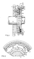
- Fig. 1 shows one of the rotatably mounted gears 1 on the one shaft 2, this gear 1 having teeth meshing with a gear (not shown) on the other shaft.
- a driving disc 3 is non-rotatably mounted on the shaft 2 with the aid of splines, such as to be axially positioned on the shaft 2 between a circlip 4 and a shoulder 5.
- the driving disc 3 is formed with four angularly uniformly distributed recesses 6, extending radially outwards for the entire width of the driving disc 3. These recesses 6, of which only one is illustrated in Fig 1, each accommodate a detent body 7, providing a radially outwardly directed force under the action of a compression spring 8. One end of the compression spring 8 is accommodated in a bore in the detent body 7.
- the detent bodies 7 have a substantially cylindrical shape, which tapers off in a radially outward direction.
- the bodies 7 are adapted to fit into an annular groove 9 in a clutch collar 10 surrounding the driving disc 3, the groove 9 being formed with sloping side surfaces.
- the clutch collar 10 is formed with internal, axial engagement teeth 11, which are continuously in mesh with complemental external teeth 12 on the driving disc 3, thus providing mutual non-rotatable engagement between thee two parts.
- the clutch collar 10 is also formed with an external annular groove 13, in which an unillustrated engaging fork is arranged to operate.
- the engaging fork is part of an operating mechanism, with the aid of which the clutch collar 10 may be axially displaced to and from engagement with the gear 1.
- the gear 1 is formed with engagement teeth 14 for meshing with the engagement teeth 11 on the clutch collar 10.
- a synchronising mechanism is arranged between the driving disc 3 and gear 1.
- the mechanism includes an inner synchronizing ring 15 with an exterior conical friction surface 16, an outer synchronizing ring 17 with an interior conical friction surface 18 and an intermediate double-cone synchronizing ring 19 having respectively an exterior and an interior conical friction surface 20 and 21.
- the inner synchronizing ring 15 includes a side face 22 facing towards the gear 1 and constituting a friction surface.
- the inner synchronizing ring 15 is arranged for free movement about a hub portion of the driving disc 3.
- the inner synchronizing ring 15 has recesses 30 with substantially axial extension. Between the recesses 28,29 in the respective synchronizing rings 17,15 there are thus formed axial abutments which in a similar way as a dog clutch engage the flaps 27,28 of the reaction disc 26 to form a non-rotatable union.
- the reaction disc 26 is movable in an axial direction, both relative the outer as well as the inner synchronizing ring 17,15. It is, however, essential that the reaction disc 26 is axially movable relative to at least one of the outer or the inner synchronizing rings 17,15, and there should therefore be a certain amount of clearance between the flaps 27,28 of the reaction disc and the accommodating recesses 29,30 in the synchronizing rings.
- the synchronizing mechanism functions in the following manner: it is assumed that the shaft 2 and the gear 1 originally had different rotational speeds.
- the engagement movement is initiated by the clutch collar 10 being moved towards the gear 1, i.e. to the left in Fig 1.
- the detent bodies 7 are then also acted on by an axial force, which by engagement against the abutments 25 of the outer synchronizing ring 17 also urges it axially into engagement with the intermediate synchronizing ring 19.
- This ring is mounted for axial movement on the locating pins 23, and is thus given an axial movement such as to come into engagement with the inner synchronizing ring 15. Also this ring is axially movable but is finally caused to engage its side face 22 against the gear 1.
- the engagement teeth 14 on the gear 1 are also formed with sloping end surfaces 33 to facilitate, if necessary, relative rotation between the collar 10 and the gear 1 during engagement.
- the sloping end surfaces on the engagement teeth 33 of the gear 1 also have the same angle a as the detent teeth 24 on the synchronizing ring 17, and, in accordance with this embodiment, the engagement teeth 11 on the clutch collar 10 also.
- the angle a is advantageously between 90 and 100 degrees.
- the illustrated embodiment solely illustrates a synchronizing mechanism and one gear.
- a further gear and synchronizing mechanism can be arranged on the other side of the driving disc, whereby a plurality of parts can be common to both synchronizing mechanisms.
Landscapes
- Engineering & Computer Science (AREA)
- General Engineering & Computer Science (AREA)
- Mechanical Engineering (AREA)
- Mechanical Operated Clutches (AREA)
Applications Claiming Priority (2)
| Application Number | Priority Date | Filing Date | Title |
|---|---|---|---|
| SE8601304A SE448182B (sv) | 1986-03-20 | 1986-03-20 | Synkroniseringsmekanism vid en vexellada |
| SE8601304 | 1986-03-20 |
Publications (2)
| Publication Number | Publication Date |
|---|---|
| EP0240475A1 true EP0240475A1 (de) | 1987-10-07 |
| EP0240475B1 EP0240475B1 (de) | 1991-02-27 |
Family
ID=20363911
Family Applications (1)
| Application Number | Title | Priority Date | Filing Date |
|---|---|---|---|
| EP87850079A Expired EP0240475B1 (de) | 1986-03-20 | 1987-03-11 | Synchronisierungsmechanismus für Getriebe |
Country Status (4)
| Country | Link |
|---|---|
| US (1) | US4807733A (de) |
| EP (1) | EP0240475B1 (de) |
| DE (1) | DE3768116D1 (de) |
| SE (1) | SE448182B (de) |
Cited By (3)
| Publication number | Priority date | Publication date | Assignee | Title |
|---|---|---|---|---|
| EP0664411A1 (de) * | 1993-12-27 | 1995-07-26 | Eaton Corporation | Synchronisiereinrichtung mit Bolzen |
| DE19740355C1 (de) * | 1997-09-13 | 1999-01-28 | Ford Global Tech Inc | Drehfeste Verbindung eines Kupplungsringes einer Synchronisiereinheit mit einem Zahnrad |
| FR3060077A1 (fr) * | 2016-12-08 | 2018-06-15 | Peugeot Citroen Automobiles Sa | Systeme de synchronisation pour boite de vitesses comportant une liaison d’armement reliee au pignon |
Families Citing this family (3)
| Publication number | Priority date | Publication date | Assignee | Title |
|---|---|---|---|---|
| US5560461A (en) * | 1995-02-24 | 1996-10-01 | Dana Corporation | Multiple cone synchronizer for vehicle transmission |
| SE511438C2 (sv) * | 1997-12-15 | 1999-09-27 | Volvo Lastvagnar Ab | Synkroniseringsanordning i en fordonsväxellåda |
| SE518727C2 (sv) * | 2001-12-17 | 2002-11-12 | Scania Cv Abp | Byggsystem för synkroniseringsanordningar till en växellåda |
Citations (6)
| Publication number | Priority date | Publication date | Assignee | Title |
|---|---|---|---|---|
| US2515010A (en) * | 1945-06-16 | 1950-07-11 | Nash Kelvinator Corp | Synchronizer |
| FR1385860A (fr) * | 1964-03-03 | 1965-01-15 | Smith & Sons Ltd S | Perfectionnements aux mécanismes à engrènement synchronisé, notamment pour changements de vitesses |
| GB1125946A (en) * | 1964-10-16 | 1968-09-05 | Smiths Industries Ltd | Improvements in or relating to dog clutches |
| DE1906863A1 (de) * | 1969-02-12 | 1970-08-27 | Zahnradfabrik Friedrichshafen | Sperrsynchronisierung fuer Zahnraederwechselgetriebe |
| DE1910884A1 (de) * | 1969-03-04 | 1970-09-10 | Zahnradfabrik Friedrichshafen | Synchronisiervorrichtung fuer Zahnraederwechselgetriebe |
| FR2556437A1 (fr) * | 1983-12-13 | 1985-06-14 | Renault Vehicules Ind | Dispositif de synchronisation triple |
Family Cites Families (3)
| Publication number | Priority date | Publication date | Assignee | Title |
|---|---|---|---|---|
| GB1102991A (en) * | 1963-03-04 | 1968-02-14 | Smith S Ind Ltd | Improvements in or relating to synchromesh mechanism |
| US3272291A (en) * | 1964-08-03 | 1966-09-13 | Borg Warner | Synchronizer |
| US4445602A (en) * | 1981-11-20 | 1984-05-01 | General Motors Corporation | Gear synchronizer for a power transmission |
-
1986
- 1986-03-20 SE SE8601304A patent/SE448182B/sv not_active IP Right Cessation
-
1987
- 1987-03-11 EP EP87850079A patent/EP0240475B1/de not_active Expired
- 1987-03-11 DE DE8787850079T patent/DE3768116D1/de not_active Expired - Lifetime
- 1987-03-20 US US07/028,585 patent/US4807733A/en not_active Expired - Fee Related
Patent Citations (6)
| Publication number | Priority date | Publication date | Assignee | Title |
|---|---|---|---|---|
| US2515010A (en) * | 1945-06-16 | 1950-07-11 | Nash Kelvinator Corp | Synchronizer |
| FR1385860A (fr) * | 1964-03-03 | 1965-01-15 | Smith & Sons Ltd S | Perfectionnements aux mécanismes à engrènement synchronisé, notamment pour changements de vitesses |
| GB1125946A (en) * | 1964-10-16 | 1968-09-05 | Smiths Industries Ltd | Improvements in or relating to dog clutches |
| DE1906863A1 (de) * | 1969-02-12 | 1970-08-27 | Zahnradfabrik Friedrichshafen | Sperrsynchronisierung fuer Zahnraederwechselgetriebe |
| DE1910884A1 (de) * | 1969-03-04 | 1970-09-10 | Zahnradfabrik Friedrichshafen | Synchronisiervorrichtung fuer Zahnraederwechselgetriebe |
| FR2556437A1 (fr) * | 1983-12-13 | 1985-06-14 | Renault Vehicules Ind | Dispositif de synchronisation triple |
Cited By (3)
| Publication number | Priority date | Publication date | Assignee | Title |
|---|---|---|---|---|
| EP0664411A1 (de) * | 1993-12-27 | 1995-07-26 | Eaton Corporation | Synchronisiereinrichtung mit Bolzen |
| DE19740355C1 (de) * | 1997-09-13 | 1999-01-28 | Ford Global Tech Inc | Drehfeste Verbindung eines Kupplungsringes einer Synchronisiereinheit mit einem Zahnrad |
| FR3060077A1 (fr) * | 2016-12-08 | 2018-06-15 | Peugeot Citroen Automobiles Sa | Systeme de synchronisation pour boite de vitesses comportant une liaison d’armement reliee au pignon |
Also Published As
| Publication number | Publication date |
|---|---|
| DE3768116D1 (de) | 1991-04-04 |
| SE448182B (sv) | 1987-01-26 |
| SE8601304D0 (sv) | 1986-03-20 |
| US4807733A (en) | 1989-02-28 |
| EP0240475B1 (de) | 1991-02-27 |
Similar Documents
| Publication | Publication Date | Title |
|---|---|---|
| US5588516A (en) | Synchronizer with self-energizing | |
| US4905806A (en) | Synchronizing shift clutch toothing arrangement | |
| CA1262102A (en) | Inertia lock type synchronous clutch mechanism | |
| EP0423863A1 (de) | Planetengetriebe mit Synchronisiereinrichtung | |
| PL130974B1 (en) | Synchro-mesh gear of locking type for changeable transmission gears | |
| JPS5831493B2 (ja) | ヘンソクハグルマデンドウソウチ | |
| JPH07208496A (ja) | 同期クラッチ機構 | |
| US4823631A (en) | Transmission synchronizer | |
| US4674346A (en) | Transmission with reverse and fifth speed synchronizer | |
| GB2142390A (en) | Synchronizing positive clutches | |
| EP0240475B1 (de) | Synchronisierungsmechanismus für Getriebe | |
| CA1277611C (en) | Inertia lock type synchronous clutch mechanism | |
| US4566569A (en) | Synchronizing mechanism in a vehicle gearbox | |
| EP0465080B1 (de) | Selbstverstärkende Synchronisiereinrichtung | |
| US4623054A (en) | Dual reversed cone synchronizing clutch | |
| GB2065800A (en) | Synchronizer for motor vehicle gearboxes | |
| CA2137948C (en) | Synchronizer with self-energizing | |
| US5785162A (en) | Re-indexing manual transmission synchronizer | |
| EP0195519B1 (de) | Zahnradsynchromechanismus im Kraftgetriebe | |
| JP2002213488A (ja) | 自己増力式同期装置 | |
| EP1209377B1 (de) | Synchronisiereinrichtung | |
| US20010011624A1 (en) | Synchronizer | |
| EP0145388B1 (de) | Zahnradsynchro für Kraftgetriebe | |
| EP1992831B1 (de) | Synchronisiereinheit für ein Getriebe eines Kraftfahrzeugs | |
| KR100375491B1 (ko) | 핀형동기장치 |
Legal Events
| Date | Code | Title | Description |
|---|---|---|---|
| PUAI | Public reference made under article 153(3) epc to a published international application that has entered the european phase |
Free format text: ORIGINAL CODE: 0009012 |
|
| AK | Designated contracting states |
Kind code of ref document: A1 Designated state(s): DE FR GB IT NL |
|
| 17P | Request for examination filed |
Effective date: 19880331 |
|
| 17Q | First examination report despatched |
Effective date: 19890120 |
|
| GRAA | (expected) grant |
Free format text: ORIGINAL CODE: 0009210 |
|
| ITF | It: translation for a ep patent filed | ||
| AK | Designated contracting states |
Kind code of ref document: B1 Designated state(s): DE FR GB IT NL |
|
| ET | Fr: translation filed | ||
| ITF | It: translation for a ep patent filed | ||
| PGFP | Annual fee paid to national office [announced via postgrant information from national office to epo] |
Ref country code: NL Payment date: 19910331 Year of fee payment: 5 |
|
| REF | Corresponds to: |
Ref document number: 3768116 Country of ref document: DE Date of ref document: 19910404 |
|
| PLBE | No opposition filed within time limit |
Free format text: ORIGINAL CODE: 0009261 |
|
| STAA | Information on the status of an ep patent application or granted ep patent |
Free format text: STATUS: NO OPPOSITION FILED WITHIN TIME LIMIT |
|
| 26N | No opposition filed | ||
| PG25 | Lapsed in a contracting state [announced via postgrant information from national office to epo] |
Ref country code: NL Effective date: 19921001 |
|
| NLV4 | Nl: lapsed or anulled due to non-payment of the annual fee | ||
| PGFP | Annual fee paid to national office [announced via postgrant information from national office to epo] |
Ref country code: FR Payment date: 19960126 Year of fee payment: 10 |
|
| REG | Reference to a national code |
Ref country code: FR Ref legal event code: TP |
|
| PGFP | Annual fee paid to national office [announced via postgrant information from national office to epo] |
Ref country code: GB Payment date: 19960304 Year of fee payment: 10 |
|
| REG | Reference to a national code |
Ref country code: GB Ref legal event code: 732E |
|
| PG25 | Lapsed in a contracting state [announced via postgrant information from national office to epo] |
Ref country code: GB Effective date: 19970311 |
|
| GBPC | Gb: european patent ceased through non-payment of renewal fee |
Effective date: 19970311 |
|
| PG25 | Lapsed in a contracting state [announced via postgrant information from national office to epo] |
Ref country code: FR Free format text: LAPSE BECAUSE OF NON-PAYMENT OF DUE FEES Effective date: 19971128 |
|
| REG | Reference to a national code |
Ref country code: FR Ref legal event code: ST |
|
| PGFP | Annual fee paid to national office [announced via postgrant information from national office to epo] |
Ref country code: DE Payment date: 19990319 Year of fee payment: 13 |
|
| PG25 | Lapsed in a contracting state [announced via postgrant information from national office to epo] |
Ref country code: DE Free format text: LAPSE BECAUSE OF NON-PAYMENT OF DUE FEES Effective date: 20010103 |
|
| PG25 | Lapsed in a contracting state [announced via postgrant information from national office to epo] |
Ref country code: IT Free format text: LAPSE BECAUSE OF NON-PAYMENT OF DUE FEES;WARNING: LAPSES OF ITALIAN PATENTS WITH EFFECTIVE DATE BEFORE 2007 MAY HAVE OCCURRED AT ANY TIME BEFORE 2007. THE CORRECT EFFECTIVE DATE MAY BE DIFFERENT FROM THE ONE RECORDED. Effective date: 20050311 |